O 10v dimming wiring diagram Idea
Home » Trend » O 10v dimming wiring diagram Idea
Your O 10v dimming wiring diagram images are ready. O 10v dimming wiring diagram are a topic that is being searched for and liked by netizens now. You can Get the O 10v dimming wiring diagram files here. Get all royalty-free photos and vectors.
If you’re searching for o 10v dimming wiring diagram images information linked to the o 10v dimming wiring diagram topic, you have pay a visit to the right site. Our website frequently gives you suggestions for seeking the maximum quality video and image content, please kindly surf and locate more informative video content and images that fit your interests.
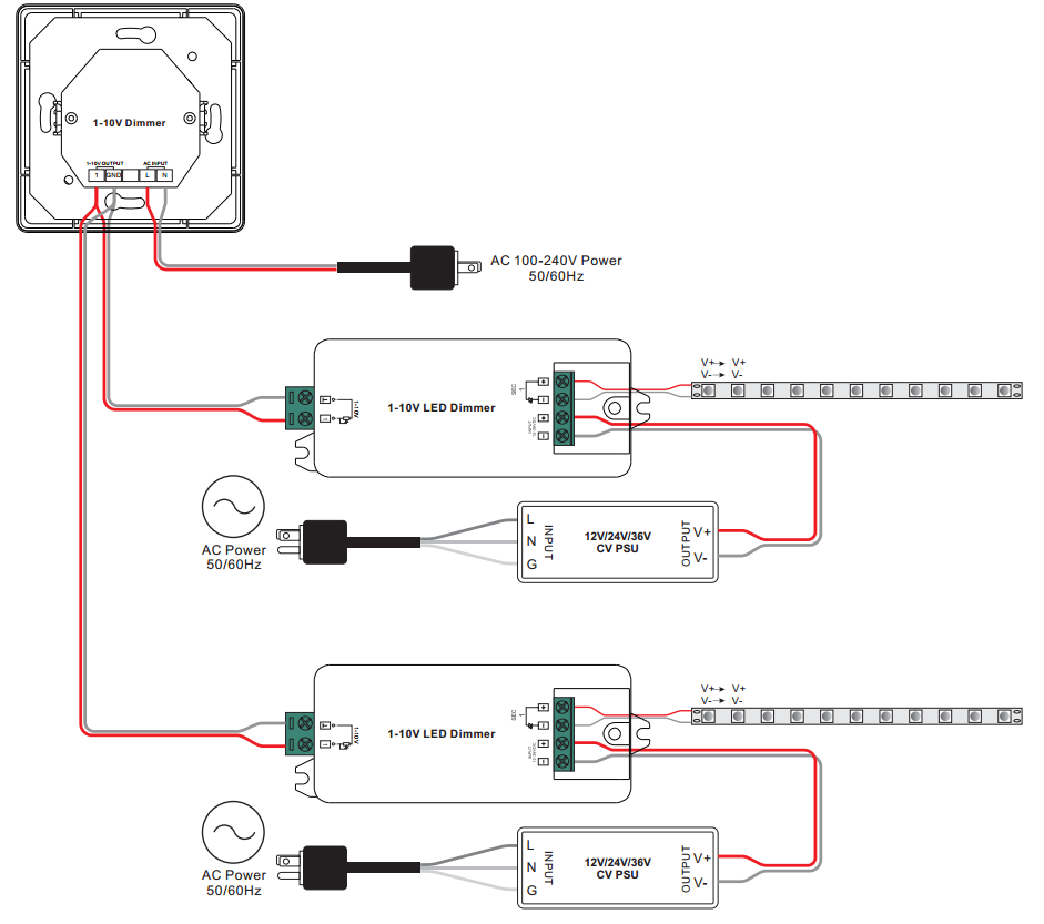
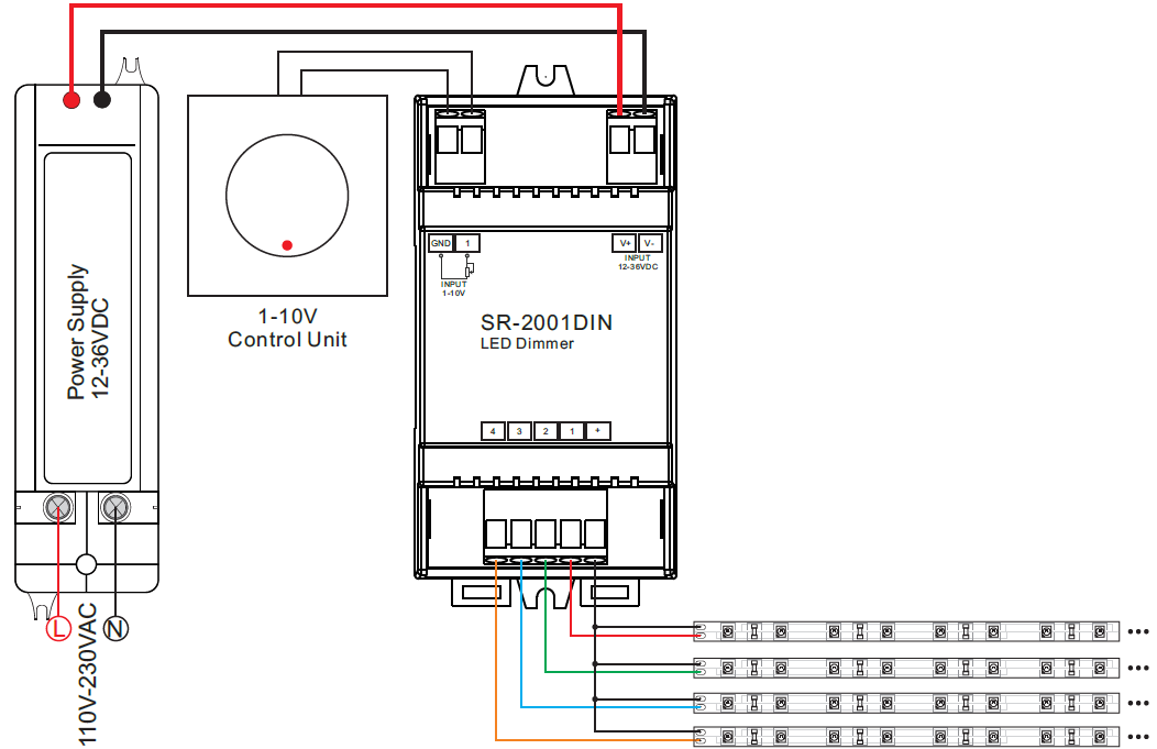
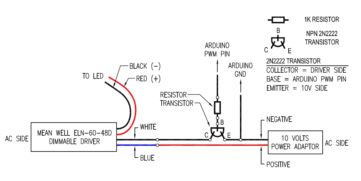
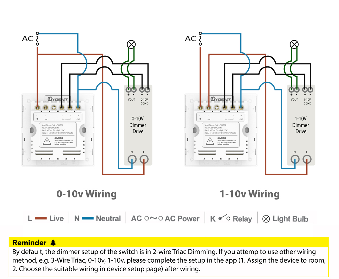
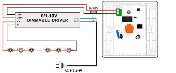
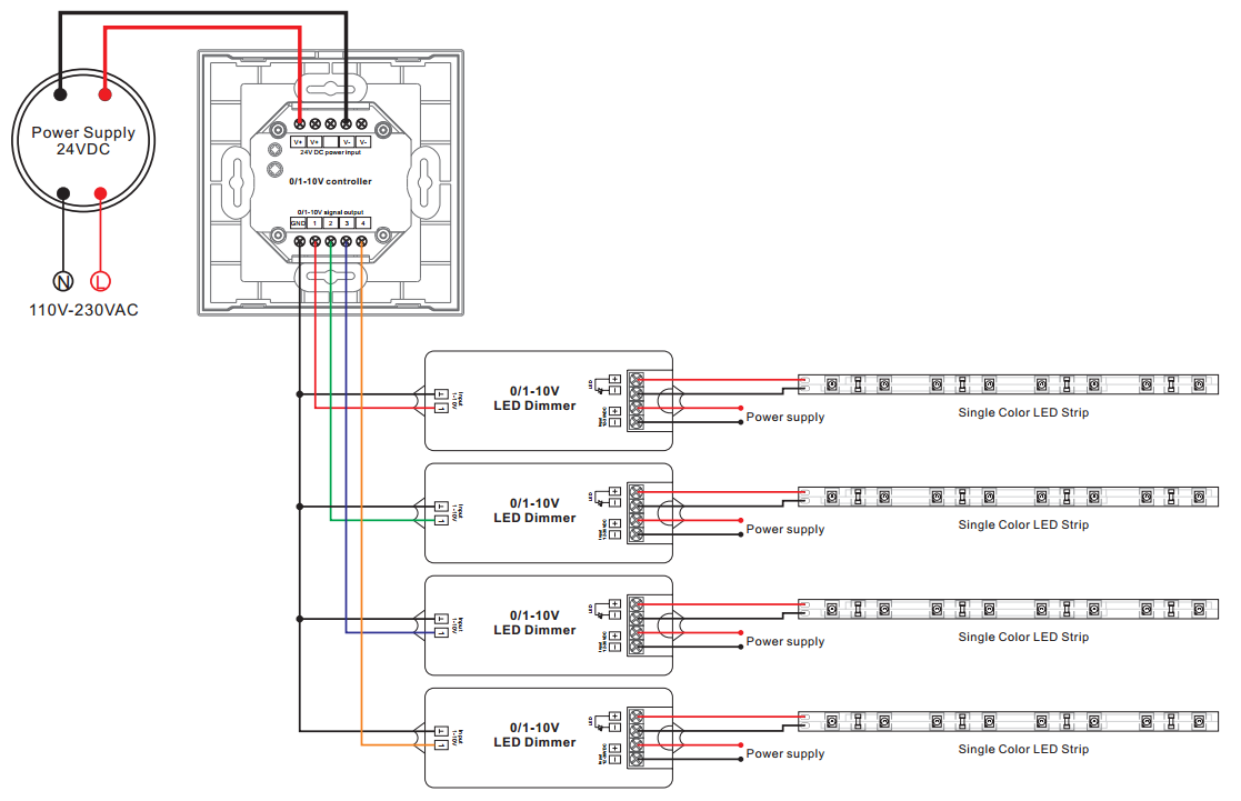
O 10v Dimming Wiring Diagram. Wiring without relay no power switching connect the control as shown in figure b2. Changing the slider position will alter light intensity. Passive infrared (pir) + daylight: Simply put, the control signal is a dc voltage that varies between zero and ten volts.
 AC Input 110V Rotary Dimmer SR2202N110V From sunricher.com
Color wire goes where on a light switch resources whole rotary led dimmer universal ledsmart dimmers installation and mechanism wiring technical brochure ing to old electrical ks 811 smart wall wifi 1 10v dc dimming controller sal diagrams do it how replace with built in off 4062eledm ms18007 two way switched lighting circuits detail 17 february 2012 electrics single. It is the default dimming driver provided with our warm glow dimming, color select and max output product lines, among others. Simply put, the control signal is a dc voltage that varies between zero and ten volts. Important:if installed as class 2, all devices in the circuit must be class 2 rated and this dimmer must be wired per instructions below. Changing the slider position will alter light intensity. Work with power repeater to expand output unlimitedly.
Depending on the information we had from adwords, maestro 0 10v dimming wiring diagram has very much search in google web engine.
Simply put, the control signal is a dc voltage that varies between zero and ten volts. Important:if installed as class 2, all devices in the circuit must be class 2 rated and this dimmer must be wired per instructions below. Ground wire to make a secure connection to the safety ground of the electrical the control4® v dimmer operates independently or as part of a control4. Dimming color* package count ; Passive infrared (pir) + daylight: Depending on the information we had from adwords, maestro 0 10v dimming wiring diagram has very much search in google web engine.
 Source: sunricher.com
Color wire goes where on a light switch resources whole rotary led dimmer universal ledsmart dimmers installation and mechanism wiring technical brochure ing to old electrical ks 811 smart wall wifi 1 10v dc dimming controller sal diagrams do it how replace with built in off 4062eledm ms18007 two way switched lighting circuits detail 17 february 2012 electrics single. Turn off the panel if you spin to the leftmost end (a click can be heard). • most fixtures are sourcing and require a sinking control, per standards as specified by iec 60629. It reveals the elements of the circuit as streamlined shapes and also the power as well as signal links between the tools. Diva preset v dimmer provides dimming control of led drivers, fluorescent ballasts and hid ballasts.
 Source: forum.arduino.cc
Simply put, the control signal is a dc voltage that varies between zero and ten volts. Contact switch control voltage 1. Diva preset v dimmer provides dimming control of led drivers, fluorescent ballasts and hid ballasts. 240v only because i will have two separate circuits feeding multiple rows of lights. It is the default dimming driver provided with our warm glow dimming, color select and max output product lines, among others.
 Source: esop-power.com
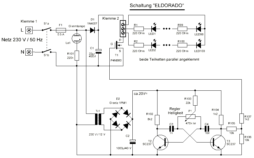
Wiring diagram also gives beneficial suggestions for tasks that might demand some additional equipment. Counterclockwise spin the knob, the brightness decreases. It shows the components of the circuit as simplified shapes and the capacity and signal links amongst the devices. • most fixtures are sourcing and require a sinking control, per standards as specified by iec 60629. Available satin and glossy finishes.
 Source: facybulka.me
It is the default dimming driver provided with our warm glow dimming, color select and max output product lines, among others. Diva preset v dimmer provides dimming control of led drivers, fluorescent ballasts and hid ballasts. • most fixtures are sourcing and require a sinking control, per standards as specified by iec 60629. Passive infrared (pir) + daylight: Auto on to 50% (partial on) 1:
 Source: ottima-tech.com
Passive dual technology (pir/acoustic) + daylight: It reveals the elements of the circuit as streamlined shapes and also the power as well as signal links between the tools. Ground wire to make a secure connection to the safety ground of the electrical the control4® v dimmer operates independently or as part of a control4. Passive dual technology (pir/acoustic) + daylight: Determine where you will run the wires and if any tools will be required to do taht.
 Source: sunricher.com
Passive dual technology (pir/acoustic) 2: Diva preset v dimmer provides dimming control of led drivers, fluorescent ballasts and hid ballasts. Contact switch control voltage 1. Determine how many lights will be run off of the switch. Work with power repeater to expand output unlimitedly.
 Source: store.yoswit.com
Diva preset v dimmer provides dimming control of led drivers, fluorescent ballasts and hid ballasts. Wiring diagram also gives beneficial suggestions for tasks that might demand some additional equipment. Passive infrared (pir) + daylight: Passive dual technology (pir/acoustic) + daylight: Wiring without relay no power switching connect the control as shown in figure b2.
 Source: chinasuppliers.buy.ecer.com
Work with power repeater to expand output unlimitedly. Diva preset v dimmer provides dimming control of led drivers, fluorescent ballasts and hid ballasts. Counterclockwise spin the knob, the brightness decreases. 240v only because i will have two separate circuits feeding multiple rows of lights. Determine where you will run the wires and if any tools will be required to do taht.
 Source: facybulka.me
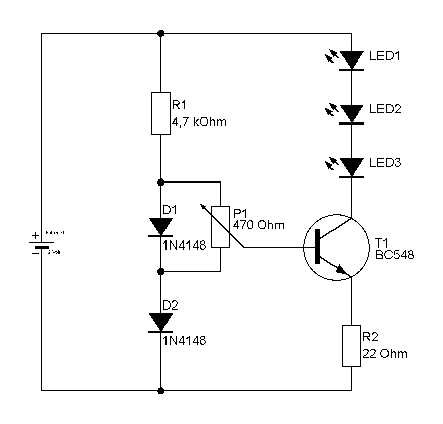
Available satin and glossy finishes. Passive dual technology (pir/acoustic) 2: Low voltage 3 way dimmer wiring diagram wiring diagram. Available satin and glossy finishes. Turn off the panel if you spin to the leftmost end (a click can be heard).
 Source: arenaluci.it
Depending on the information we had from adwords, maestro 0 10v dimming wiring diagram has very much search in google web engine. Work with power repeater to expand output unlimitedly. I am wiring a residential large shop, so open ceilings and romex for power. 240v only because i will have two separate circuits feeding multiple rows of lights. Auto on to 50% (partial on) 1:
 Source: virtuaalivalonneulenurkkaus.blogspot.com
Color wire goes where on a light switch resources whole rotary led dimmer universal ledsmart dimmers installation and mechanism wiring technical brochure ing to old electrical ks 811 smart wall wifi 1 10v dc dimming controller sal diagrams do it how replace with built in off 4062eledm ms18007 two way switched lighting circuits detail 17 february 2012 electrics single. • most fixtures are sourcing and require a sinking control, per standards as specified by iec 60629. Important:if installed as class 2, all devices in the circuit must be class 2 rated and this dimmer must be wired per instructions below. Counterclockwise spin the knob, the brightness decreases. Ground wire to make a secure connection to the safety ground of the electrical the control4® v dimmer operates independently or as part of a control4.
 Source: skippingtheinbetween.blogspot.com
This simple lighting control system connects to your led fixtures to provide multipurpose lighting solutions and ambiance. Determine how many lights will be run off of the switch. Determine where you will run the wires and if any tools will be required to do taht. Work with power repeater to expand output unlimitedly. Color wire goes where on a light switch resources whole rotary led dimmer universal ledsmart dimmers installation and mechanism wiring technical brochure ing to old electrical ks 811 smart wall wifi 1 10v dc dimming controller sal diagrams do it how replace with built in off 4062eledm ms18007 two way switched lighting circuits detail 17 february 2012 electrics single.
 Source: bosco-mylove.blogspot.com
Work with power repeater to expand output unlimitedly. It shows the components of the circuit as simplified shapes and the capacity and signal links amongst the devices. Changing the slider position will alter light intensity. Available satin and glossy finishes. Important:if installed as class 2, all devices in the circuit must be class 2 rated and this dimmer must be wired per instructions below.
Source: atkinsjewelry.blogspot.com
• most fixtures are sourcing and require a sinking control, per standards as specified by iec 60629. Dimming color* package count ; Available satin and glossy finishes. Determine where you will run the wires and if any tools will be required to do taht. Low voltage 3 way dimmer wiring diagram wiring diagram.
 Source: wisecontrols.com
Depending on the information we had from adwords, maestro 0 10v dimming wiring diagram has very much search in google web engine. Work with power repeater to expand output unlimitedly. Wiring diagram also gives beneficial suggestions for tasks that might demand some additional equipment. It reveals the elements of the circuit as streamlined shapes and also the power as well as signal links between the tools. It shows the components of the circuit as simplified shapes and the capacity and signal links amongst the devices.
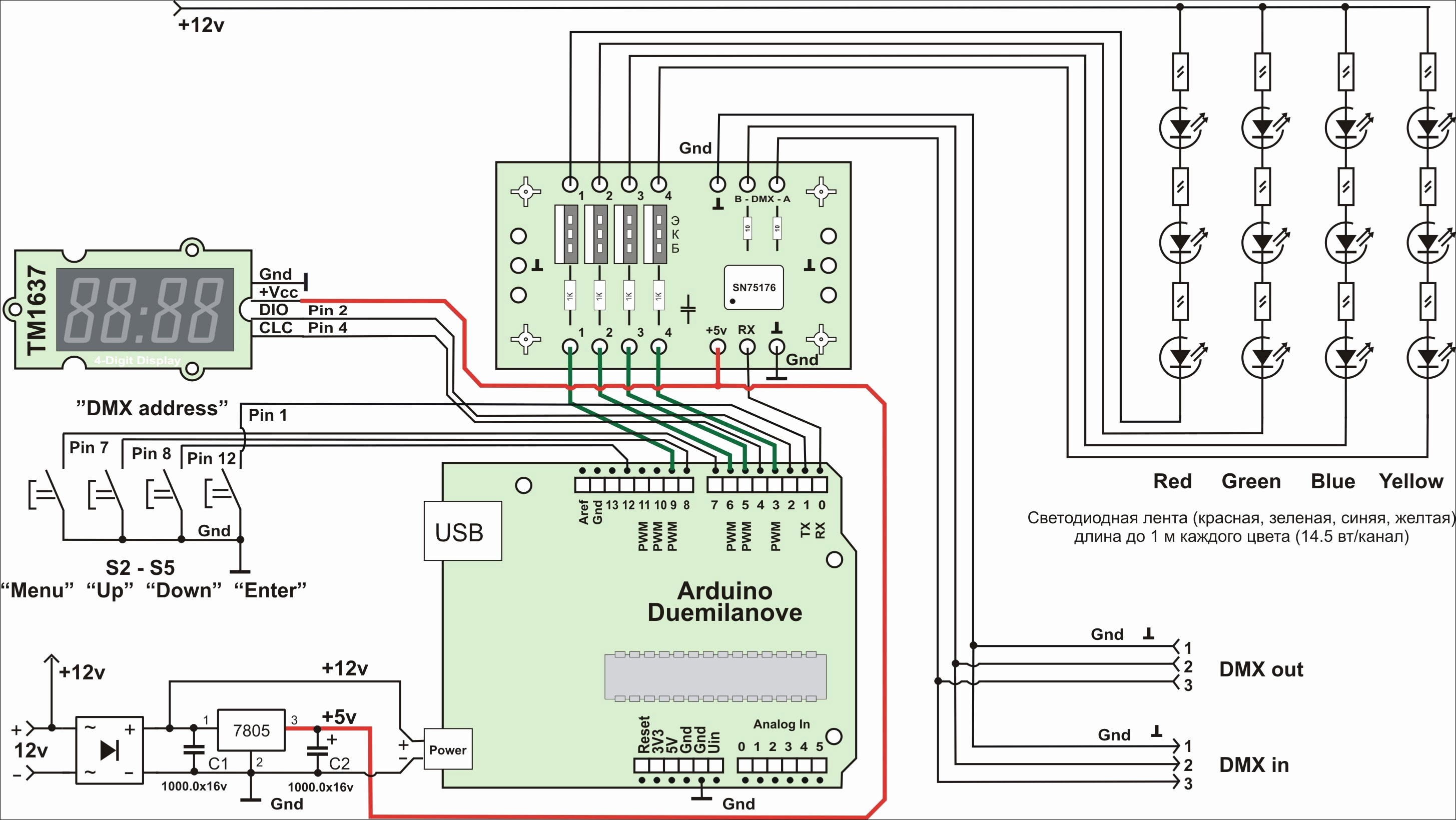 Source: hanenhuusholli.blogspot.com
Wiring diagram also gives beneficial suggestions for tasks that might demand some additional equipment. Simply put, the control signal is a dc voltage that varies between zero and ten volts. Ground wire to make a secure connection to the safety ground of the electrical the control4® v dimmer operates independently or as part of a control4. Simply put, the control signal is a dc voltage that varies between zero and ten volts. Color wire goes where on a light switch resources whole rotary led dimmer universal ledsmart dimmers installation and mechanism wiring technical brochure ing to old electrical ks 811 smart wall wifi 1 10v dc dimming controller sal diagrams do it how replace with built in off 4062eledm ms18007 two way switched lighting circuits detail 17 february 2012 electrics single.
 Source: facybulka.me
Counterclockwise spin the knob, the brightness decreases. This simple lighting control system connects to your led fixtures to provide multipurpose lighting solutions and ambiance. Passive dual technology (pir/acoustic) 2: Low voltage 3 way dimmer wiring diagram wiring diagram. Passive dual technology (pir/acoustic) + daylight:
 Source: manualsdir.com
Dimming color* package count ; Work with power repeater to expand output unlimitedly. Ground wire to make a secure connection to the safety ground of the electrical the control4® v dimmer operates independently or as part of a control4. I am wiring a residential large shop, so open ceilings and romex for power. Available satin and glossy finishes.
This site is an open community for users to do sharing their favorite wallpapers on the internet, all images or pictures in this website are for personal wallpaper use only, it is stricly prohibited to use this wallpaper for commercial purposes, if you are the author and find this image is shared without your permission, please kindly raise a DMCA report to Us.
If you find this site serviceableness, please support us by sharing this posts to your favorite social media accounts like Facebook, Instagram and so on or you can also bookmark this blog page with the title o 10v dimming wiring diagram by using Ctrl + D for devices a laptop with a Windows operating system or Command + D for laptops with an Apple operating system. If you use a smartphone, you can also use the drawer menu of the browser you are using. Whether it’s a Windows, Mac, iOS or Android operating system, you will still be able to bookmark this website.
Category
Related By Category
- Predator 670 engine wiring diagram Idea
- Frsky x8r wiring diagram information
- Pioneer ts wx130da wiring diagram Idea
- Johnson 50 hp wiring diagram Idea
- Kohler voltage regulator wiring diagram Idea
- Johnson 50 hp outboard wiring diagram information
- Kti hydraulic remote wiring diagram Idea
- Pyle plpw12d wiring diagram information
- Tx9600ts wiring diagram information
- Lifan 50cc wiring diagram information