Humminbird transducer wiring diagram Idea
Home » Trending » Humminbird transducer wiring diagram Idea
Your Humminbird transducer wiring diagram images are ready. Humminbird transducer wiring diagram are a topic that is being searched for and liked by netizens today. You can Download the Humminbird transducer wiring diagram files here. Find and Download all royalty-free images.
If you’re looking for humminbird transducer wiring diagram pictures information connected with to the humminbird transducer wiring diagram interest, you have come to the right blog. Our site always gives you suggestions for viewing the highest quality video and picture content, please kindly surf and find more enlightening video content and graphics that fit your interests.
Humminbird Transducer Wiring Diagram. Just enter the first few numbers of the part number and see the results immediately. Airmar�s transducer cross reference offers a variety of transducer information—from wiring diagrams to sounder compatibility and more. Center one clamp half over the bumper as shown in the illustration. With these wiring diagrams, you can be confident that you�ll start the fish finder install process with all of the cables and accessories you need for.
 Eagle Transducer Humminbird Adapter Wiring Diagram From diagramweb.net
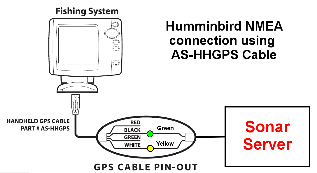
The transducer plug has 5 pins. Humminbird dx 200 transducer hookup first, make sure you know what tranducer you have. This manual was written in english and may have been translated to another language. The gps antenna plug has 4 pins and the com port on the unit has 6 holes. The blue wire is your nmea out connection. The connector is keyed to prevent reversed installation, and insertion should be easy.
For inboard boats , mount the transducer ahead of the propeller(s) and shaft(s).
Connect the transducer cable to the transducer port on the control head or cable connector (if applicable). Humminbird is not responsible for incorrect translations or discrepancies between documents. For inboard boats , mount the transducer ahead of the propeller(s) and shaft(s). The transducer plug has 5 pins. The unit receptacle has 7 holes. Wiring diagram for whirlpool wtw4950xw0 washer.
 Source: manualsdir.com
Just enter the first few numbers of the part number and see the results immediately. Before attempting to rewire a transducer connector you should: Pick the diagram that is most like the scenario you are in and see if you can wire your switch! Greg or wiringall.com you post a wiring diagram for a two transducer system for my on here. The transducer must use c32 or c332 cable.
 Source: schematron.org
Greg or wiringall.com you post a wiring diagram for a two transducer system for my on here. Videos you watch may be. 837 loop and segment diagram. Drill the four mounting screw holes using a 5/32 (4 mm) drill bit. Place the bumper into the groove of the trolling motor shaft.
 Source: wholefoodsonabudget.com
The mount that attaches the transducer to the boat hull is separate. I figured out the power but there are too many combinations for the transducer. Or for the humminbird either. Transducer, and external garmin gpsmap 76 series. January 4, 2018in this video i will show you how to methodically troubleshoot problems with a humminbird fishfinder and transducer.
 Source: diagramweb.net
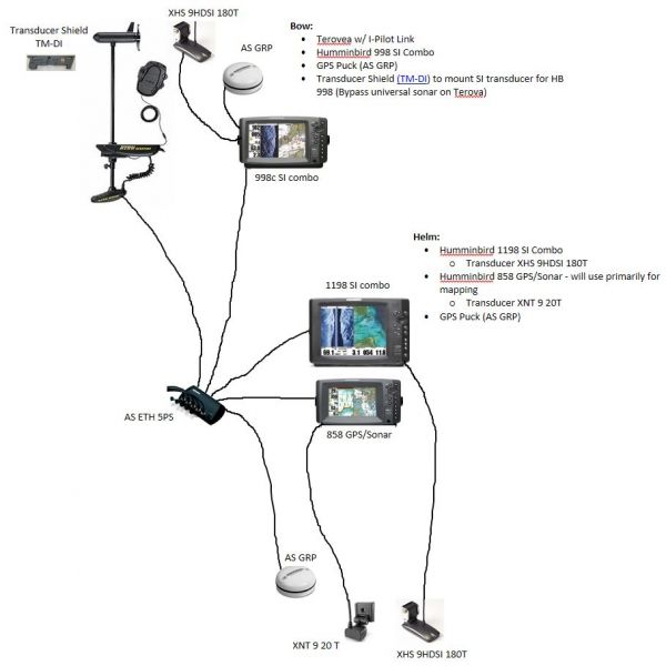
Drill the four mounting screw holes using a 5/32 (4 mm) drill bit. Videos you watch may be. Installation diagrams console & bow mount humminbird units the following schematic outlines the necessary accessories/cables needed to connect two humminbird units. 837 loop and segment diagram. I assume you are tryin to splice in your 2 pin connector to the new transducer.
 Source: wiringdiagramall.blogspot.com
The into on the tab is below. Just enter the first few numbers of the part number and see the results immediately. Here are the pics of each the round one is the garmin. Low profile design minimize snags. The power cord plug has 2 pins and the unit power receptacle has two holes.
 Source: sonarserver.com
The mount that attaches the transducer to the boat hull is separate. I figured out the power but there are too many combinations for the transducer. With these wiring diagrams, you can be confident that you�ll start the fish finder install process with all of the cables and accessories you need for. Wiring diagram for whirlpool wtw4950xw0 washer. You will use this hole for routing the cables to the control head in another section.
 Source: schematron.org
On humminbird piranha 20 transducer wiring diagram. Or for the humminbird either. You will use this hole for routing the cables to the control head in another section. Xtm 9 wide di 20 t. Please choose a year from the menu at left to start your search.
 Source: wiringall.com
*also requires lowrance adapter cable part number these diagrams are for the use of professional installers. The power cord plug has 2 pins and the unit power receptacle has two holes. This manual was written in english and may have been translated to another language. Xtm 9 wide di 20 t. Compatible accessories helix series solix series
 Source: schematron.org
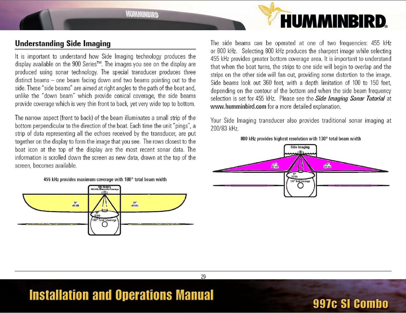
Installation is shown with a gps/heading sensor and high speed transducer. Installation is shown with a gps/heading sensor and high speed transducer. The connector is keyed to prevent reversed installation, and insertion should be easy. Pick the diagram that is most like the scenario you are in and see if you can wire your switch! For fin keel sailboats , mount the transducer to the side of the centerline and forward of the fin keel 1� to 2�.
 Source: schematron.org
I am adding the 2d transducer to the. I figured out the power but there are too many combinations for the transducer. January 4, 2018in this video i will show you how to methodically troubleshoot problems with a humminbird fishfinder and transducer. Humminbird dx 200 transducer hookup first, make sure you know what tranducer you have. On humminbird piranha 20 transducer wiring diagram.
 Source: schematron.org
Transducer, and external garmin gpsmap 76 series. 837 loop and segment diagram. If playback doesn�t begin shortly, try restarting your device. I can�t find a wiring diagram that shows what pins on the garmin side are for the existing garmin transducer. I am adding the 2d transducer to the.
 Source: diagramweb.net
Installation is shown with a gps/ heading sensor and additional high speed transducer. If playback doesn�t begin shortly, try restarting your device. Greg or wiringall.com you post a wiring diagram for a two transducer system for my on here. You will use this hole for routing the cables to the control head in another section. Xtm 9 wide di 20 t.
 Source: diagramweb.net
Down imaging™/dualbeam plus™, 75°/45°, 455/800 khz (di) and 25°/16°, 200/455 khz, with built in temperature, 15� cable. If so, you can simply. Here are the pics of each the round one is the garmin. If playback doesn�t begin shortly, try restarting your device. The procedures and features described in this manual are subject to change without notice.
 Source: schematron.org
Just enter the first few numbers of the part number and see the results immediately. The into on the tab is below. Pick the diagram that is most like the scenario you are in and see if you can wire your switch! This video will show a hu. 837 loop and segment diagram.
 Source: schematron.org
The unit receptacle has 7 holes. Wiring color code diagram for transducer techniques load cells available online for download or viewing, come checkout other online services. Installation is shown with a gps/heading sensor and high speed transducer. Drill the four mounting screw holes using a 5/32 (4 mm) drill bit. Installation is shown with a gps/ heading sensor and additional high speed transducer.
 Source: diagramweb.net
I assume you are tryin to splice in your 2 pin connector to the new transducer. Before attempting to rewire a transducer connector you should: January 4, 2018in this video i will show you how to methodically troubleshoot problems with a humminbird fishfinder and transducer. Humminbird networking diagrams 530503 4 b trolling motor tx w mount fish finder 110 user guide install 6 pager nmea 2000 190cx 180x 170x 160x 150x pmax143 153180 opm en manualzz helix product manual 2109 531324 1 d s 530511 3 a 917c installation and operations. Humminbird helix adds mega imaging and dual spectrum chirp to product features.
 Source: schematron.org
Here are the pics of each the round one is the garmin. It has the same wiring diagram that i linked to above. If you spend some serious time (or want to start spending serious time) on the water, this is the book you need. Installation diagrams console & bow mount humminbird units the following schematic outlines the necessary accessories/cables needed to connect two humminbird units. I assume you are tryin to splice in your 2 pin connector to the new transducer.
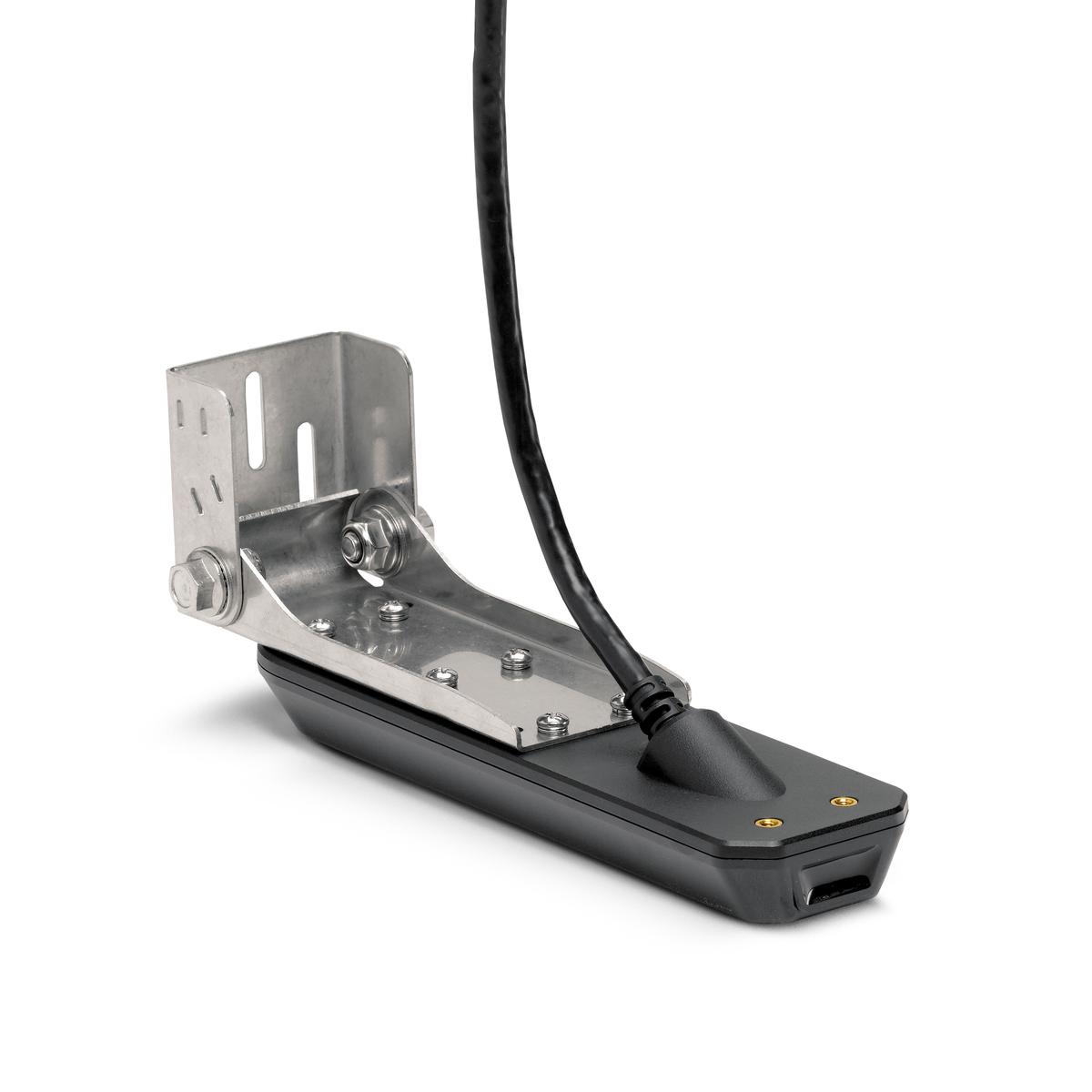 Source: humminbird.com.au
837 loop and segment diagram. The transducer plug has 5 pins. Down imaging™/dualbeam plus™, 75°/45°, 455/800 khz (di) and 25°/16°, 200/455 khz, with built in temperature, 15� cable. Please choose a year from the menu at left to start your search. Jon thelen and todd hesse discuss troubleshooting power issues which may occur with your humminbird electronics.
This site is an open community for users to do submittion their favorite wallpapers on the internet, all images or pictures in this website are for personal wallpaper use only, it is stricly prohibited to use this wallpaper for commercial purposes, if you are the author and find this image is shared without your permission, please kindly raise a DMCA report to Us.
If you find this site value, please support us by sharing this posts to your preference social media accounts like Facebook, Instagram and so on or you can also bookmark this blog page with the title humminbird transducer wiring diagram by using Ctrl + D for devices a laptop with a Windows operating system or Command + D for laptops with an Apple operating system. If you use a smartphone, you can also use the drawer menu of the browser you are using. Whether it’s a Windows, Mac, iOS or Android operating system, you will still be able to bookmark this website.
Category
Related By Category
- Truck lite wiring diagram Idea
- Single phase motor wiring with contactor diagram information
- Magic horn wiring diagram Idea
- Two plate stove wiring diagram information
- Kettle lead wiring diagram information
- Hubsan x4 wiring diagram Idea
- Wiring diagram for 8n ford tractor information
- Winch control box wiring diagram Idea
- Zongshen 250 quad wiring diagram information
- Ninebot es4 wiring diagram information