Zener barrier wiring diagram information
Home » Trending » Zener barrier wiring diagram information
Your Zener barrier wiring diagram images are available in this site. Zener barrier wiring diagram are a topic that is being searched for and liked by netizens now. You can Download the Zener barrier wiring diagram files here. Download all royalty-free vectors.
If you’re searching for zener barrier wiring diagram images information linked to the zener barrier wiring diagram interest, you have pay a visit to the right site. Our site frequently provides you with suggestions for seeking the highest quality video and image content, please kindly surf and find more informative video articles and images that fit your interests.
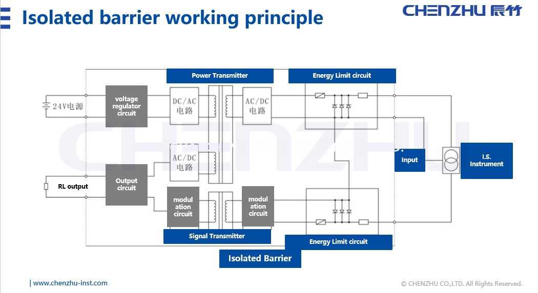
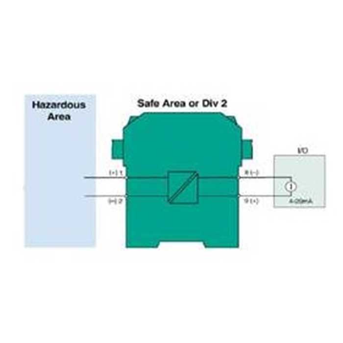
Zener Barrier Wiring Diagram. Circuit diagram for an intrinsically safe barrier is shown in figure 2. A key advantage of isolated barriers is that they do not require a ground between the module and the intrinsically safe device. Our 937t isolator barriers include galvanic optical or transformer isolation, these modules provide an interface within the intrinsic safety circuit that is electrically separated from the control system. Tragic light boom barrier control with arduino via ethernet arduino project hub.
 Intrinsic Safety Explosionproof Barrier Zenerbarrier(for From valcom.co.jp
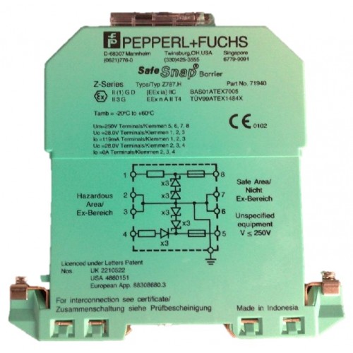
(max 200m / vprnp guage pressure · w(waterproof connector): Zener bridge rectifier circuit description: Z 788.h (for analog current output) hazardous area safe area power supply negative important: Special models with pressure capsulated casings for the hazardous area are available on demand. A key advantage of isolated barriers is that they do not require a ground between the module and the intrinsically safe device. Circuit diagram for an intrinsically safe barrier is shown in figure 2.
The zener diodes in the zener barrier are connected in the reverse direction.
To set up a boom barrier you must first install a loop. (max 200m / vprnp guage pressure · w(waterproof connector): Tragic light boom barrier control with arduino via ethernet arduino project hub. Available in positive or negative polarity, these barriers simply snap on for easy installation and maintenance. Our zener barriers include positive. Our bulletin 937z zener barriers provide protection for electrical signals within hazardous areas.
 Source: acornfiresecurity.com
The cable recommended for the wiring within the hazardous area is an ölflex cable 2x0,75 mm², max. Our zener barriers include positive. Circuit of the connecting wiring in the hazardous area or a connection to earth of the wiring attached to terminal 1, as the fuse blows. Z 722 (for digital current output) b) wiring with zener barrier pepperl + fuchs mod. The underlying concern breeds the suspicion that satisfactory earthing is difficult.
 Source: valcom.co.jp
Leading distributor of electronic components, electric. A wiring diagram is a streamlined conventional photographic depiction of an electrical circuit. Zener barrier wiring diagram d c. Seven ‘key’ mtl700 range of models are highlighted in the sales literature as meeting most process control requirements. Zener barrier wiring diagram d c.
 Source: milworks.com.sg
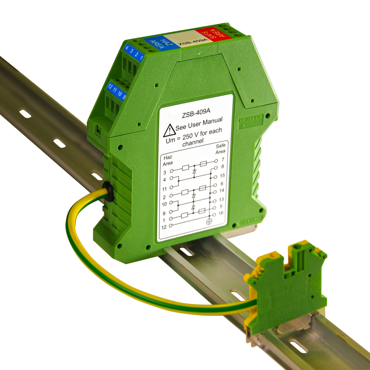
A resistor, at least two zener diodes, and a fuse.the resistor limits the current to a specific value known as the short circuit current, isc.the zener diode limits the voltage to a value referred to as. Series zener barrier wiring diagram d.c. Series zener barrier wiring diagram d.c. These barriers feature a narrow profile of just 12.5 mm to maximize control panel space. (max 200m / vprnp guage pressure · w(waterproof connector):
 Source: studylib.net
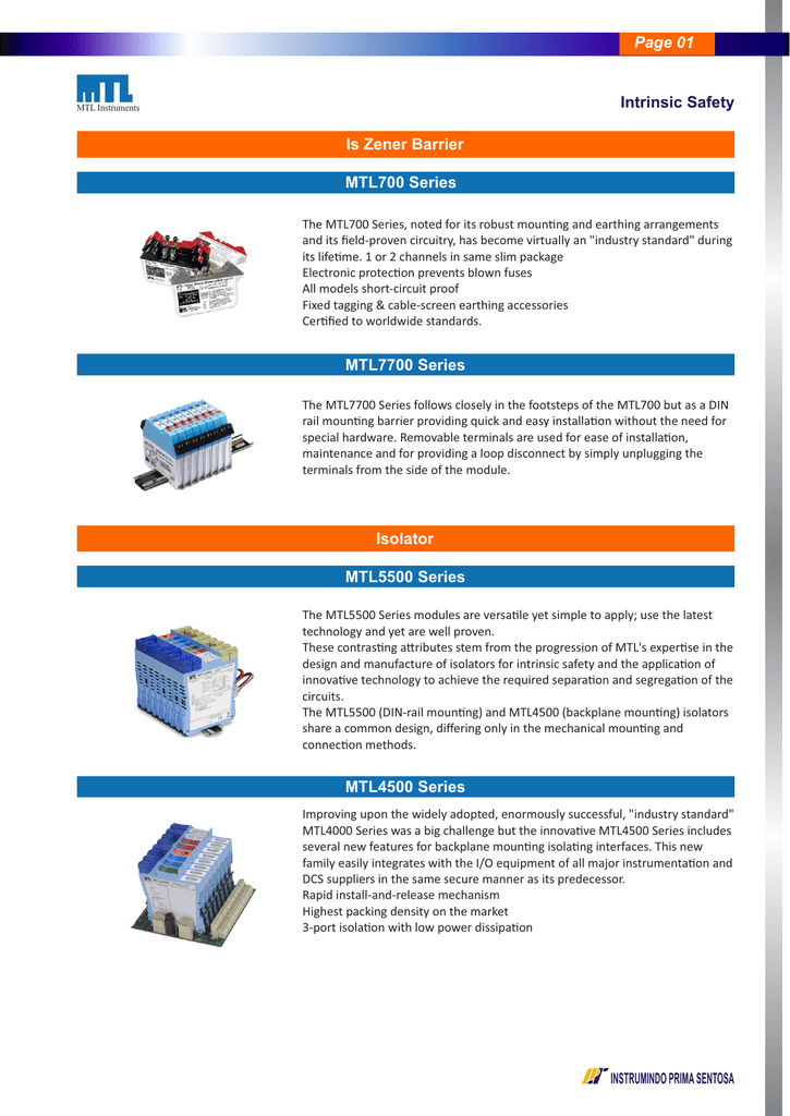
Hazardous area approvals are carried by the barrier manufacturer. Zener barrier wiring diagram d c. Series zener barrier wiring diagram d.c. The breakdown voltage of the diodes is not exceeded in normal operation. Seven ‘key’ mtl700 range of models are highlighted in the sales literature as meeting most process control requirements.
 Source: deeterelectronics.com
Wiring diagram 12.0724.0001 page 1 of 2 _____ 02/28/2002 a) wiring with zener barrier pepperl + fuchs mod. When considering the intrinsically safe circuit in a control system, there are three main components: Zener barrier wiring diagram d c. Zener bridge rectifier circuit description: Seven ‘key’ mtl700 range of models are highlighted in the sales literature as meeting most process control requirements.
 Source: fuelminder.biz
(max 200m / vprnp guage pressure · w(waterproof connector): Circuit of the connecting wiring in the hazardous area or a connection to earth of the wiring attached to terminal 1, as the fuse blows. Circuit diagram for an intrinsically safe barrier is shown in figure 2. The earthing or grounding of zener barrier installations in intrinsically safe instrumentation and control systems is a common source of concern to installation engineers. The breakdown voltage of the diodes is not exceeded in normal operation.
 Source: journal.auric.kr
The mtl700p barriers are mechanically identical to the mtl700 range of barriers and are therefore compatible with all mtl700range accessories. Typically the tip of a boom gate rises in a vertical arc to a near vertical position. The breakdown voltage of the diodes is not exceeded in normal operation. Circuit diagram for an intrinsically safe barrier is shown in figure 2. The zener barrier prevents the transfer of unacceptably high energy from the safe area into the hazardous area.
 Source: en.chenzhu-inst.com
Zener bridge rectifier circuit description: Wire entry is also angled to assist wiring within limited space enclosures. In order to achieve the necessary level of protection, There are three components to a barrier that limit current and voltage: Zener bridge rectifier circuit description:
Source: multisim.com
The mtl700p barriers are mechanically identical to the mtl700 range of barriers and are therefore compatible with all mtl700range accessories. There are three components to a barrier that limit current and voltage: Board controller for automatic boom barrier gate wj motor 110v 220v ac only no capacitor included controller control controller boardcontrol ac aliexpress. The zener diodes in the zener barrier are connected in the reverse direction. A wiring diagram is a streamlined conventional photographic depiction of an electrical circuit.
 Source: iplgroup.com
A key advantage of isolated barriers is that they do not require a ground between the module and the intrinsically safe device. A wiring diagram is a streamlined conventional photographic depiction of an electrical circuit. A key advantage of isolated barriers is that they do not require a ground between the module and the intrinsically safe device. The zener barrier prevents the transfer of unacceptably high energy from the safe area into the hazardous area. Our 937t isolator barriers include galvanic optical or transformer isolation, these modules provide an interface within the intrinsic safety circuit that is electrically separated from the control system.
 Source: manualsdir.com
The underlying concern breeds the suspicion that satisfactory earthing is difficult. Wire entry is also angled to assist wiring within limited space enclosures. The fuse will open when the zener diode conducts thereby further protecting the circuit. If this voltage is exceeded, due to a fault in the safe area, the. The barriers limit the el ectrical energy towards the ha zardous area by means of a combination of zener diodes, resistors and fuses.
 Source: google.tl
These models and their applications are listed in table 1. There are three components to a barrier that limit current and voltage: The barriers limit the el ectrical energy towards the ha zardous area by means of a combination of zener diodes, resistors and fuses. The breakdown voltage of the diodes is not exceeded in normal operation. Circuit of the connecting wiring in the hazardous area or a connection to earth of the wiring attached to terminal 1, as the fuse blows.

These models and their applications are listed in table 1. If this voltage is exceeded, due to a fault in the safe area, the. These models and their applications are listed in table 1. The mtl700p barriers are mechanically identical to the mtl700 range of barriers and are therefore compatible with all mtl700range accessories. (max 200m / vprnp guage pressure · w(waterproof connector):
 Source: c-tec.com
Wire entry is also angled to assist wiring within limited space enclosures. The zener barrier prevents the transfer of unacceptably high energy from the safe area into the hazardous area. Wire entry is also angled to assist wiring within limited space enclosures. 1) the field device (can be either a simple or. Wiring diagram 12.0724.0001 page 1 of 2 _____ 02/28/2002 a) wiring with zener barrier pepperl + fuchs mod.
 Source: google.com
Wiring diagram 12.0724.0001 page 1 of 2 _____ 02/28/2002 a) wiring with zener barrier pepperl + fuchs mod. 1) the field device (can be either a simple or. Seven ‘key’ mtl700 range of models are highlighted in the sales literature as meeting most process control requirements. The mtl700p barriers are mechanically identical to the mtl700 range of barriers and are therefore compatible with all mtl700range accessories. The earthing or grounding of zener barrier installations in intrinsically safe instrumentation and control systems is a common source of concern to installation engineers.
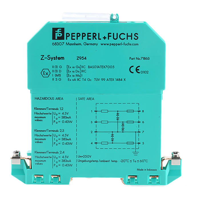
(max 200m / vprnp guage pressure · w(waterproof connector): Zener barriers the applied voltage is increased. The operating range of a zener barrier must therefore be such that it is below the zener voltage, so that the leakage current is restricted to a minimum. Our bulletin 937z zener barriers provide protection for electrical signals within hazardous areas. If the zener barriers are provided with a re sistor, this limits th e short circuit current to a safe value in the event of a short circuit of the connecting wiring in the hazardous area or a connection to earth of the wiring attached to terminal 1.
 Source: aiidien.blogspot.com
Typically the tip of a boom gate rises in a vertical arc to a near vertical position. In order to achieve the necessary level of protection, Circuit diagram for an intrinsically safe barrier is shown in figure 2. Zener barriers are normally tested to check that at the prescribed voltage the leakage current is smaller than 10 µα. The zener diodes in the zener barrier are connected in the reverse direction.

The fuse will open when the zener diode conducts thereby further protecting the circuit. Typically the tip of a boom gate rises in a vertical arc to a near vertical position. (max 200m / vprnp guage pressure · w(waterproof connector): The zener barrier prevents the transfer of unacceptably high energy from the safe area into the hazardous area. • the intrinsically safe system can be used in zone 0.
This site is an open community for users to do submittion their favorite wallpapers on the internet, all images or pictures in this website are for personal wallpaper use only, it is stricly prohibited to use this wallpaper for commercial purposes, if you are the author and find this image is shared without your permission, please kindly raise a DMCA report to Us.
If you find this site helpful, please support us by sharing this posts to your favorite social media accounts like Facebook, Instagram and so on or you can also bookmark this blog page with the title zener barrier wiring diagram by using Ctrl + D for devices a laptop with a Windows operating system or Command + D for laptops with an Apple operating system. If you use a smartphone, you can also use the drawer menu of the browser you are using. Whether it’s a Windows, Mac, iOS or Android operating system, you will still be able to bookmark this website.
Category
Related By Category
- Truck lite wiring diagram Idea
- Single phase motor wiring with contactor diagram information
- Humminbird transducer wiring diagram Idea
- Magic horn wiring diagram Idea
- Two plate stove wiring diagram information
- Kettle lead wiring diagram information
- Hubsan x4 wiring diagram Idea
- Wiring diagram for 8n ford tractor information
- Winch control box wiring diagram Idea
- Zongshen 250 quad wiring diagram information