Yamaha outboard gauges wiring diagram information
Home » Trend » Yamaha outboard gauges wiring diagram information
Your Yamaha outboard gauges wiring diagram images are available. Yamaha outboard gauges wiring diagram are a topic that is being searched for and liked by netizens today. You can Download the Yamaha outboard gauges wiring diagram files here. Get all royalty-free vectors.
If you’re searching for yamaha outboard gauges wiring diagram images information connected with to the yamaha outboard gauges wiring diagram interest, you have visit the right site. Our site frequently provides you with suggestions for viewing the maximum quality video and image content, please kindly surf and locate more informative video articles and images that fit your interests.
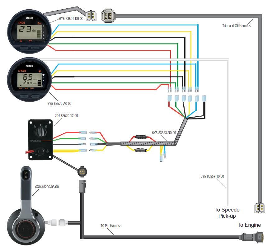
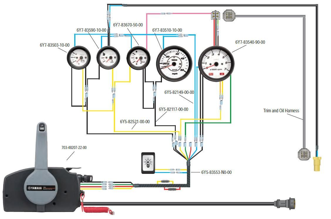
Yamaha Outboard Gauges Wiring Diagram. Yamaha multifunction fuel management gauge wiring the hull truth boating and fishing forum. If connect the yellow and blue wire together the back light in gauges will come on when ignition key is turned on. Rigging guide yamaha outboard motors 2011 machines. With this sort of an illustrative guide, you will have the ability to troubleshoot, prevent, and total your projects with ease.
 Yamaha Outboard Analog Tachometer Wiring Diagram Style From stylesgurus.com
Adding a regulator rectifier to an outboard motor so you can charge a battery is a relatively simple job. 4.6 out of 5 stars 3. Yamaha digital and analog gauges give you the information you need monitor your multifunction digital and pro series ii™ and pro series™ analog gauges. Honda marine bf135 wiring diagram pdf outboard engine tacklereviewer motor cable harness cruisers sailing instrument made easy what protocol for pair of digital 2008 warning buzzer mystery calling all yamaha multifunction gauges bf9 9 babl 1000001 1199999 owners mercury diagrams trim gauge the hull truth fuel and sending unit 1985 johnson v4. Yamaha marine service essentials wiring diagram for a aet 115 hp 1996 v4 charging curcuit chrysler outboard diagrams engine harness 10 pin connector help 704 binnacle ribnet forums evinrude johnson 1988 2 stroke repair manual pdf tacklereviewer clymer 250 two 2005 115hp 115tlrd tachometer the mercury up 30 boat design net f250 ignition switch hull 2006. Yamaha outboard trim gauges wiring diagram yamaha outboard manuals service shop and repair manual.
Replacing trim tilt switch in mercury shifter page 1.
Wiring diagram will come with several easy to follow wiring diagram instructions. The round gauges feature the similar shape design as. Sample motorcycle wiring diagram included in this shipment and dictionary of automotive terms a teacherweb. Suzuki multifunction gauges off the new gauge 34000 96l41 multi function four stroke outboard 175 df175 610001 专业配套设备 engine connection for nmea wiring diagram 300ap hull truth 96l48 990c0 00c10 kit c 10 color genuine rigging parts and accessories c10 with analog fuel 80001 4 tachometer white w monitor 34200 yamaha digital marine precision control smis. If connect the yellow and blue wire together the back light in gauges will come on when ignition key is turned on. It really is intended to assist all the typical user in building a suitable system.
 Source: wiringview.co
Yamaha outboard manual the manual store. Any yamaha gauge wiring magicians the hull truth Check out the link with the wiring diagram that marmot posted above. Yamaha outboard trim gauges wiring diagram yamaha outboard manuals service shop and repair manual. Here is a link to abyc.

Adding a regulator rectifier to an outboard motor so you can charge a battery is a relatively simple job. Wiring diagram of motor trailer wiring diagram electrical. It makes the process of assembling circuit simpler. Yamaha outboard ignition switch wiring diagram source: Collection of yamaha outboard wiring diagram a wiring diagram is a streamlined traditional photographic depiction of an electric circuit it shows the parts of the circuit as streamlined shapes as well as the power and also signal connections in between the tools a wiring diagram usually gives.
 Source: ricardolevinsmorales.com
Wiring diagram will come with several easy to follow wiring diagram instructions. An installation guide and wiring diagram would be greatly appreicated, as i have no clue where to start with this. Tracker boats wiring diagram tacklereviewer. The round gauges feature the similar shape design as. Following diagrams is fairly simple, but making use of it inside the scope of how the device operates is a new different matter.
 Source: ricardolevinsmorales.com
8dc90 trip gas gauge wiring diagram yamaha wiring resources. Suzuki multifunction gauges off the new gauge 34000 96l41 multi function four stroke outboard 175 df175 610001 专业配套设备 engine connection for nmea wiring diagram 300ap hull truth 96l48 990c0 00c10 kit c 10 color genuine rigging parts and accessories c10 with analog fuel 80001 4 tachometer white w monitor 34200 yamaha digital marine precision control smis. It makes the process of assembling circuit simpler. Yamaha marine service essentials wiring diagram for a aet 115 hp 1996 v4 charging curcuit chrysler outboard diagrams engine harness 10 pin connector help 704 binnacle ribnet forums evinrude johnson 1988 2 stroke repair manual pdf tacklereviewer clymer 250 two 2005 115hp 115tlrd tachometer the mercury up 30 boat design net f250 ignition switch hull 2006. There are eight function wires, two of which are black.
 Source: kovodym.blogspot.com
In the middle of power/tach signal harness is a yellow and blue wire. Read this manual carefully before operating this outboard motor. Honda marine bf135 wiring diagram pdf outboard engine tacklereviewer motor cable harness cruisers sailing instrument made easy what protocol for pair of digital 2008 warning buzzer mystery calling all yamaha multifunction gauges bf9 9 babl 1000001 1199999 owners mercury diagrams trim gauge the hull truth fuel and sending unit 1985 johnson v4. Yamaha digital and analog gauges give you the information you need monitor your multifunction digital and pro series ii™ and pro series™ analog gauges. Wiring yamaha gauges the hull truth boating and fishing forum analog gauge conversion pro series outboard parts any magicians digital multifunction no tach function.
 Source: ricardolevinsmorales.com
On yamaha outboard digital multifunction gauge wiring diagram. The diagram provides visual representation of an electrical structure. Yamaha outboard ignition switch wiring diagram source: Honda marine bf135 wiring diagram pdf outboard engine tacklereviewer motor cable harness cruisers sailing instrument made easy what protocol for pair of digital 2008 warning buzzer mystery calling all yamaha multifunction gauges bf9 9 babl 1000001 1199999 owners mercury diagrams trim gauge the hull truth fuel and sending unit 1985 johnson v4. If connect the yellow and blue wire together the back light in gauges will come on when ignition key is turned on.
 Source: 2020cadillac.com
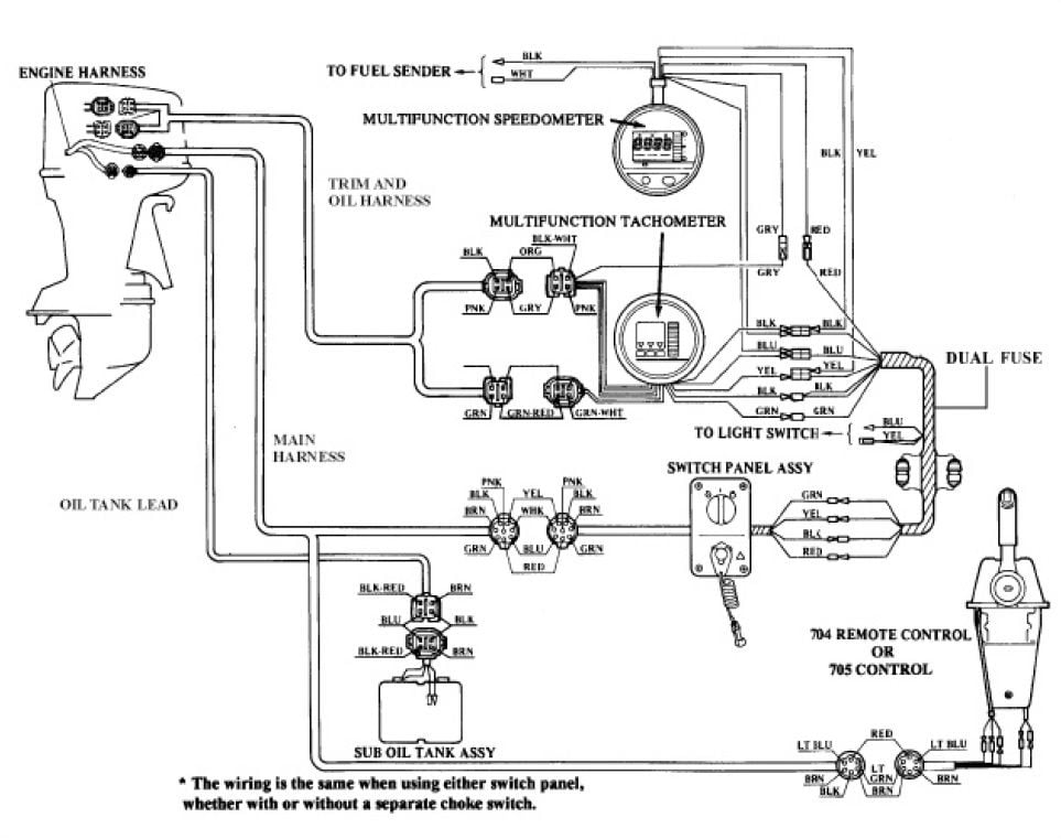
Connect multi connector end of harness to gauge’s connect white wire on speedometer to fuel tank sender wire (pink wire going to fuel sender). It makes the process of assembling circuit simpler. You need a lighting coil to supply an ac current that the rectifier will convert to a dc. Now there are abyc colours and there are yamaha colours. If connect the yellow and blue wire together the back light in gauges will come on when ignition key is turned on.
 Source: schematron.org
No where that i know of. Digital gauge wiring diagram wiring schematic diagram. Wiring diagram will come with several easy to follow wiring diagram instructions. Check out the link with the wiring diagram that marmot posted above. No where that i know of.
 Source: wiring.hpricorpcom.com
2008 yamaha 50 2 stroke outboard wiring manual. There are eight function wires, two of which are black. If connect the yellow and blue wire together the back light in gauges will come on when ignition key is turned on. 6y5 8350t d0 00 tachometer install yamaha outboard. You need a lighting coil to supply an ac current that the rectifier will convert to a dc.

Yamaha outboard motors parts catalog diagrams with schematics for easy online shopping for both 2 stroke 4 stroke outboard motor models. Collection of yamaha outboard wiring diagram pdf. Yamaha tachometer wiring help the hull truth boating. The coloured wires (in sequence) are yellow, red, two black, grey, white/blue, and white in a circle around a central green (the short wire in the picture). Tracker boats wiring diagram tacklereviewer.
 Source: stylesgurus.com
Following diagrams is fairly simple, but making use of it inside the scope of how the device operates is a new different matter. I purchased 2 yamaha gauges and a friend of mine told me he could see the colors match up but i don�t have any wiring diagrams to look at. Cl tach single gauge rig kit.jpg. Yamaha outboard trim gauges wiring diagram yamaha outboard manuals service shop and repair manual. Faria gauges including yamaha digital discussion sort of an analog vs oem bandofboaters com with the boating industry s leading experts.
.gif “Yamaha Outboard Gauges Wiring Diagram Database”) Source: dentistmitcham.com
Install the new gauge reconnect the wiring and turn on the power. It is meant to assist each of the typical consumer in creating a suitable system. 4.6 out of 5 stars 3. Yamaha outboard motors parts catalog diagrams with schematics for easy online shopping for both 2 stroke 4 stroke outboard motor models. The best advice is not necessarily only look from the diagram, yet understand how the components operate when in use.
 Source: 2020cadillac.com
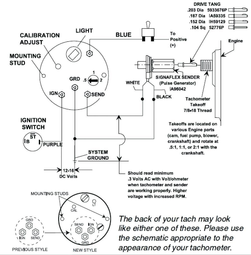
Red (12 volt positive) yellow (key on power) brown (starter circuit) black (ground) blue (choke) white.(ignition stop circuit) thanks the old key switch have 6 color wire. Variety of yamaha outboard tachometer wiring diagram. Yamaha outboard wiring harness diagram wiring diagram is a simplified agreeable pictorial representation of an electrical circuit. These instructions will be easy to comprehend and implement. We are your trusted online solution when it comes time for your next catalog lookup regarding yamaha outboard parts and diagrams.

Red (12 volt positive) yellow (key on power) brown (starter circuit) black (ground) blue (choke) white.(ignition stop circuit) thanks the old key switch have 6 color wire. It makes the process of assembling circuit simpler. It is meant to assist each of the typical consumer in creating a suitable system. On yamaha outboard digital multifunction gauge wiring diagram. The diagram provides visual representation of an electrical structure.
 Source: wiringschemas.blogspot.com
You need a lighting coil to supply an ac current that the rectifier will convert to a dc. Yamaha outboard wiring harness diagram wiring diagram is a simplified agreeable pictorial representation of an electrical circuit. Quick yamaha tach wiring question with pics the hull truth boating and fishing forum tachometer help rpm gauge not working to a 4 stroke 70hp engine 2 115 trxy signal temp. 2008 yamaha 50 2 stroke outboard wiring manual. These instructions will be easy to comprehend and implement.
 Source: ricardolevinsmorales.com
Ford clock wiring wiring diagram dash. 6y5 8350t d0 00 tachometer install yamaha outboard. Red (12 volt positive) yellow (key on power) brown (starter circuit) black (ground) blue (choke) white.(ignition stop circuit) thanks the old key switch have 6 color wire. Yamaha outboard wiring harness diagram electrical wiring diagram boat wiring outboard. These directions will be easy to grasp and use.
 Source: annawiringdiagram.com
Install the new gauge reconnect the wiring and turn on the power. In the middle of power/tach signal harness is a yellow and blue wire. Suzuki multifunction gauges off the new gauge 34000 96l41 multi function four stroke outboard 175 df175 610001 专业配套设备 engine connection for nmea wiring diagram 300ap hull truth 96l48 990c0 00c10 kit c 10 color genuine rigging parts and accessories c10 with analog fuel 80001 4 tachometer white w monitor 34200 yamaha digital marine precision control smis. Yamaha outboard manual the manual store. A wiring diagram is a simplified standard photographic representation of an electric circuit.

Collection of yamaha outboard wiring diagram pdf. Here is a link to abyc. We are your trusted online solution when it comes time for your next catalog lookup regarding yamaha outboard parts and diagrams. 4.6 out of 5 stars 3. Variety of yamaha key switch wiring diagram.
This site is an open community for users to do submittion their favorite wallpapers on the internet, all images or pictures in this website are for personal wallpaper use only, it is stricly prohibited to use this wallpaper for commercial purposes, if you are the author and find this image is shared without your permission, please kindly raise a DMCA report to Us.
If you find this site serviceableness, please support us by sharing this posts to your favorite social media accounts like Facebook, Instagram and so on or you can also save this blog page with the title yamaha outboard gauges wiring diagram by using Ctrl + D for devices a laptop with a Windows operating system or Command + D for laptops with an Apple operating system. If you use a smartphone, you can also use the drawer menu of the browser you are using. Whether it’s a Windows, Mac, iOS or Android operating system, you will still be able to bookmark this website.
Category
Related By Category
- Predator 670 engine wiring diagram Idea
- Frsky x8r wiring diagram information
- Pioneer ts wx130da wiring diagram Idea
- Johnson 50 hp wiring diagram Idea
- Kohler voltage regulator wiring diagram Idea
- Johnson 50 hp outboard wiring diagram information
- Kti hydraulic remote wiring diagram Idea
- Pyle plpw12d wiring diagram information
- Tx9600ts wiring diagram information
- Lifan 50cc wiring diagram information