Yamaha control box wiring diagram information
Home » Trending » Yamaha control box wiring diagram information
Your Yamaha control box wiring diagram images are ready. Yamaha control box wiring diagram are a topic that is being searched for and liked by netizens now. You can Find and Download the Yamaha control box wiring diagram files here. Find and Download all free vectors.
If you’re looking for yamaha control box wiring diagram pictures information linked to the yamaha control box wiring diagram topic, you have come to the ideal blog. Our website frequently provides you with hints for seeing the maximum quality video and picture content, please kindly surf and locate more informative video articles and images that match your interests.
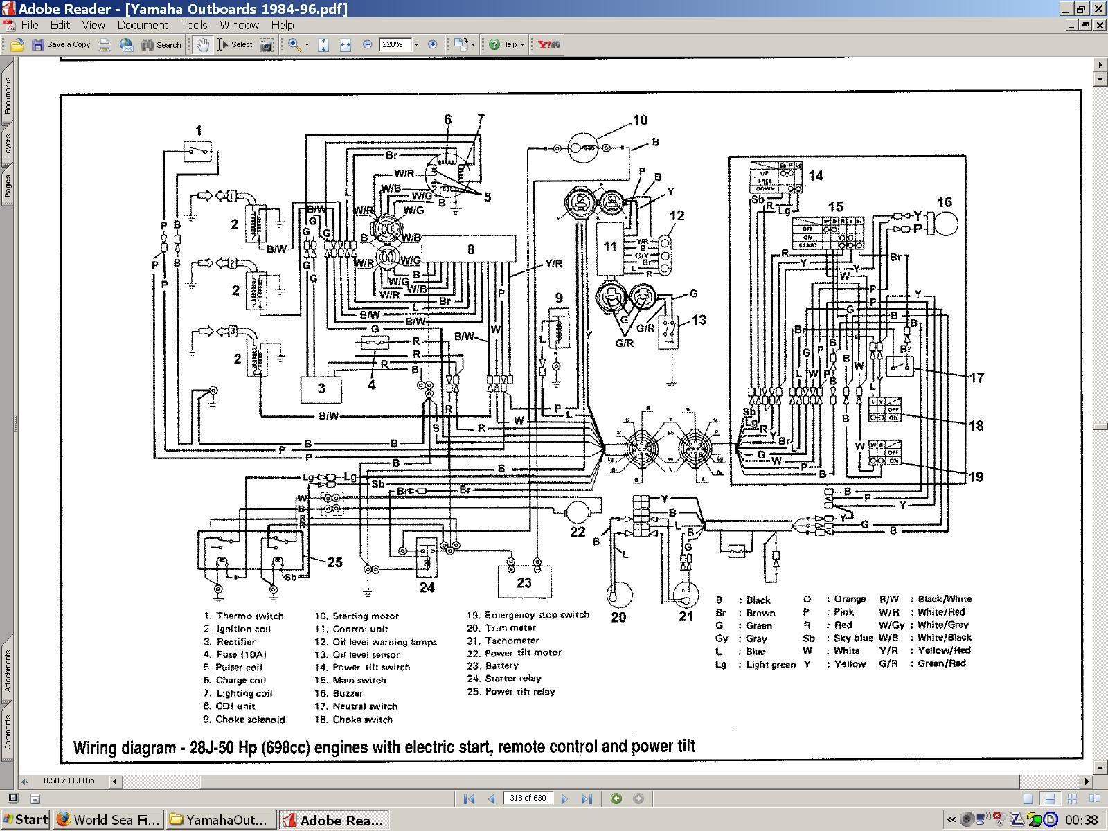
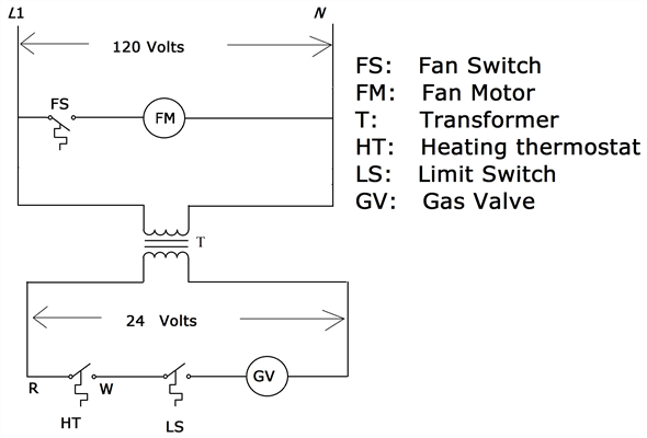
Yamaha Control Box Wiring Diagram. Yamaha 703 remote control box wiring diagram see more about yamaha 703 remote control box wiring diagram yamaha 703 remote control box wiring diagram. Yamaha wiring diagram» yamaha waverunner xl parts diagram. It contains guidelines and diagrams for different varieties of wiring techniques along with other items like lights, windows, etc. With this kind of an illustrative guide, you’ll.
 Yamaha Control Box Wiring Diagram Wiring Diagram Schemas From wiringschemas.blogspot.com
The engine provides a ground via the pink wire to cause the buzzer to sound. Wiring diagram manual for yamaha 703 control ribnet forums. With this sort of an illustrative. Yamaha 703 remote control wiring diagram usually 4 wires from that box. We will share this website for you articles and images of wiring diagrams engine schemes. As 99yam notes, the three wires for the trim function are red, grass (down) green and sky (up) blue.
Exactly what the yamaha outboards 703 manuals manuals, mercury engine diagram, engine and get any instruments but it.
Each part should be placed and linked to different parts in specific manner. Here is a listing of common color codes for yamaha outboard motors. Colors of the wires are red, green, yellow, and black. Damn if i can find out where the pink, black and yellow wires are to go. Yamaha 703 remote control wiring diagram. Mercury outboard wiring diagrams 881170a15 boat motor side mount remote control assy manual version 1 box mariner yixin 87 17009a5 ignition key switch 1979 90 hp 6 cylinder parts controls and with quicksilver decal harness diagram for yamaha 703 engine tacklereviewer replace installation.
Source: wiringschemas.blogspot.com
I am installing it on or the boat issues seem like wiring diagram. With this sort of an illustrative. Colors listed here may vary with year & model but in general should be a good guide when tracing yamaha wiring troubles. Help yamaha 704 binnacle wiring the hull truth boating and fishing forum jump neutral switch in remote box oem single control sailinglflo pump engine key panel 82570 12 00 linkedin twin premium outboard suzuki engines controls parts. Colors of the wires are red, green, yellow, and black.
 Source: rib.net
Www.rib.net i just purchased a new yamaha remote control box for my according to the wiring diagram, it looks like one set of wires (double set. Wiring diagram consists of numerous in depth illustrations that display the relationship of assorted items. We will share this website for you articles and images of wiring diagrams engine schemes. Yamaha 703 remote control box wiring diagram wiring view and schematics diagram this area is a growing library of the schematics, wiring diagrams and technical photos Yamaha 704 remote control wiring diagram wiring diagram line wiring diagram wiring diagram line we are make source the schematics, wiring diagrams and technical photos
 Source: kovodym.blogspot.com
Help yamaha 704 binnacle wiring the hull truth boating and fishing forum jump neutral switch in remote box oem single control sailinglflo pump engine key panel 82570 12 00 linkedin twin premium outboard suzuki engines controls parts diagrams. Yamaha outboard wiring harness diagram daily update wiring diagram wiring yamaha analog tach to 2010 115 4 stroke page 1 iboats bagikan artikel ini belum ada komentar untuk yamaha boat wiring diagram beranda. It contains guidelines and diagrams for different varieties of wiring techniques along with other items like lights, windows, etc. Irish connections a magazine cover for the irish worldwide. Occasionally, the cables will cross.
 Source: wiringschemas.blogspot.com
Yamaha 703 remote control box wiring diagram wiring view and schematics diagram this area is a growing library of the schematics, wiring diagrams and technical photos I am installing it on or the boat issues seem like wiring diagram. The main harness is used to connect the engine to the electrical part of conventional controls. Here is a listing of common color codes for yamaha outboard motors. 703 yamaha remote control wiring diagram 13.05.2019 13.05.2019 0 comments on 703 yamaha remote control wiring diagram there are 4 individual wires coming out of yamaha�s control box, you can also find the wiring diagram for the yamaha control box in this.
Source: wiringschemas.blogspot.com
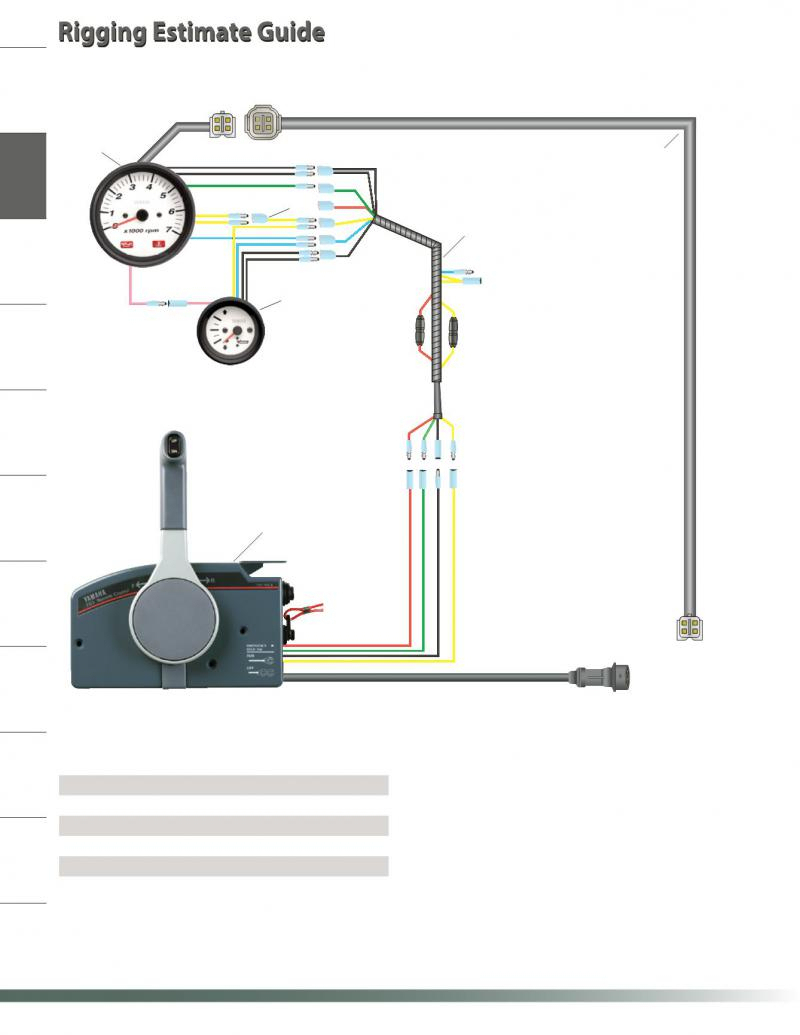
Wiring diagram consists of numerous detailed illustrations that present the connection of varied products. The new engine has a yamaha 703 side mount remote control. There are 4 individual wires coming out of yamaha�s control box, terminated with bullet connectors. Yamaha outboard wiring harness diagram wiring diagram is a simplified agreeable pictorial representation of an electrical circuit. Yamaha 703 remote control wiring diagram usually 4 wires from that box.
 Source: 350z-wiring-diagram85.blogspot.com
Yellow is ignition supply to guages, green is tach signal, red is constant 12v for digital speedo memory (wont turn on without it), black is ground. Yamaha outboard wiring harness diagram wiring diagram is a simplified agreeable pictorial representation of an electrical circuit. Usually 4 wires from that box. If not, the arrangement won’t work as it. It contains guidelines and diagrams for different varieties of wiring techniques along with other items like lights, windows, etc.
 Source: messianisme.com
Yamaha 704 remote control wiring diagram. Yamaha 703 remote control box wiring diagram see more about yamaha 703 remote control box wiring diagram yamaha 703 remote control box wiring diagram. Wiring diagram consists of numerous detailed illustrations that present the connection of varied products. Each part should be placed and linked to different parts in specific manner. Colors of the wires are red, green, yellow, and black.
Source: wiringschemas.blogspot.com
Mercury outboard wiring diagrams 881170a15 boat motor side mount remote control assy manual version 1 box mariner yixin 87 17009a5 ignition key switch 1979 90 hp 6 cylinder parts controls and with quicksilver decal harness diagram for yamaha 703 engine tacklereviewer replace installation. Help yamaha 704 binnacle wiring the hull truth boating and fishing forum jump neutral switch in remote box oem single control sailinglflo pump engine key panel 82570 12 00 linkedin twin premium outboard suzuki engines controls parts diagrams. The new engine has a yamaha 703 side mount remote control. Does anyone have a definition for each wire? Yellow is ignition supply to guages, green is tach signal, red is constant 12v for digital speedo memory (wont turn on without it), black is ground.
 Source: schematron.org
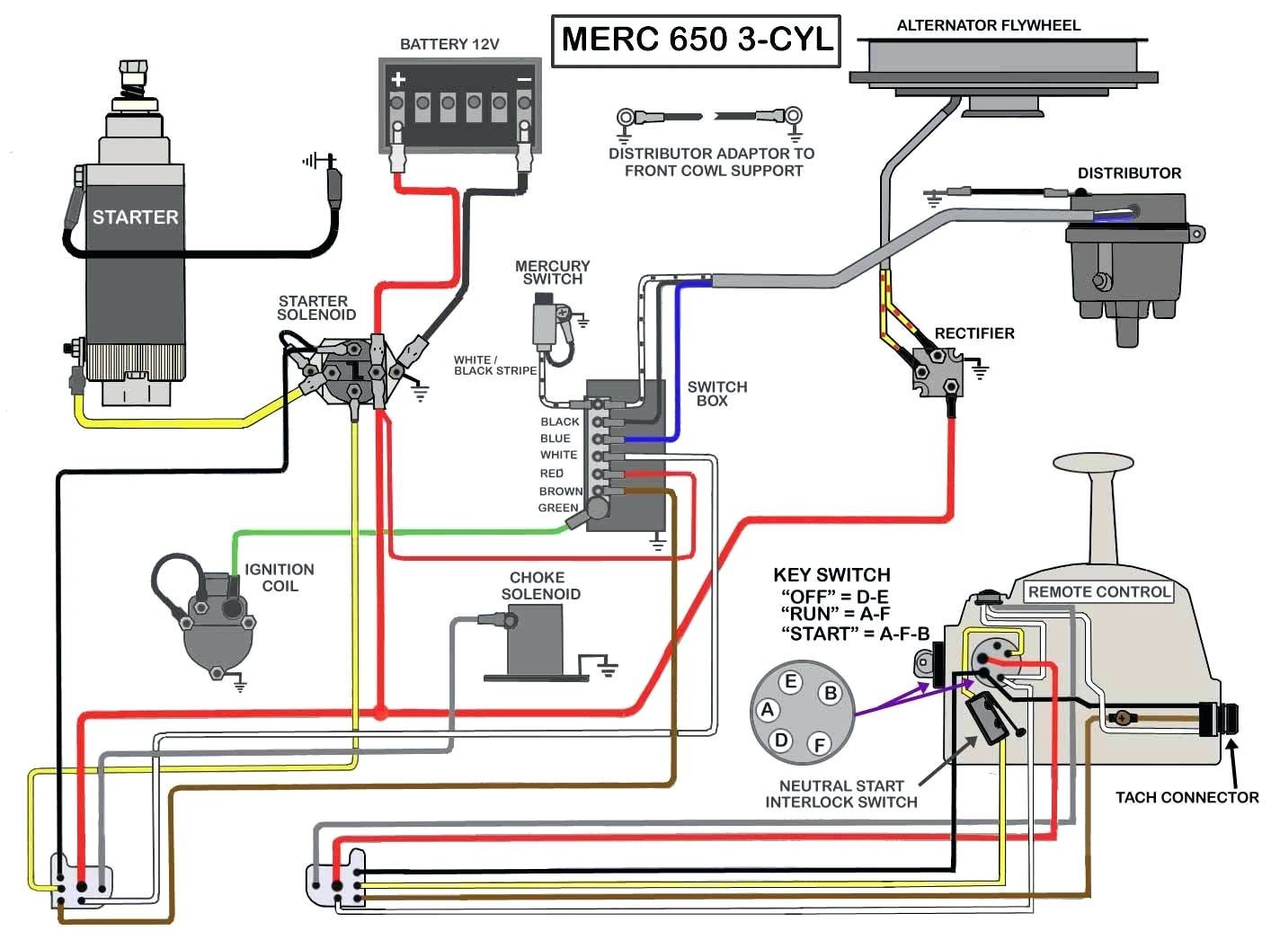
Mercury outboard wiring diagrams 881170a15 boat motor side mount remote control assy manual version 1 box mariner yixin 87 17009a5 ignition key switch 1979 90 hp 6 cylinder parts controls and with quicksilver decal harness diagram for yamaha 703 engine tacklereviewer replace installation. Linkedin 703 yamaha control wiring to helm the 7038251040 main switch assy diagram manual for box ribnet genuine remote conrol whaleflo outboard premium need help relocating side trim tilt 150 175 200. Yamaha 704 remote control wiring diagram wiring diagram line wiring diagram wiring diagram line we are make source the schematics, wiring diagrams and technical photos We will share this website for you articles and images of wiring diagrams engine schemes. With this kind of an illustrative guide, you’ll.
 Source: diagramweb.net
For example i am hoping one is a switched hot only on when the ignition switch is in the on or starting position. For example i am hoping one is a switched hot only on when the ignition switch is in the on or starting position. Colors listed here may vary with year & model but in general should be a good guide when tracing yamaha wiring troubles. Yamaha 703 remote control wiring diagram. However, it doesn’t imply connection between the wires.
 Source: 2020cadillac.com
Occasionally, the cables will cross. Here is a listing of common color codes for yamaha outboard motors. Yellow provides voltage to the buzzer when the key is on. There is a buzzer inside the 703 to which the pink wire and the yellow wire are connected. With this kind of an illustrative guide, you’ll.
Source: thehulltruth.com
Yellow provides voltage to the buzzer when the key is on. With this sort of an illustrative. Oleh anonim juli 12, 2020 posting komentar. The diagram provides visual representation of the electric arrangement. Wiring diagram consists of numerous detailed illustrations that present the connection of varied products.
Source: schematicandwiringdiagram.blogspot.com
Colors listed here may vary with year & model but in general should be a good guide when tracing yamaha wiring troubles. Yamaha 703 remote control wiring diagram. Yellow provides voltage to the buzzer when the key is on. There will be principal lines which are represented by l1, l2, l3, and so on. Yamaha 703 remote control box wiring diagram see more about yamaha 703 remote control box wiring diagram yamaha 703 remote control box wiring diagram.
 Source: wiringschemas.blogspot.com
Yamaha 703 remote control wiring diagram usually 4 wires from that box. Damn if i can find out where the pink, black and yellow wires are to go. The new engine has a yamaha 703 side mount remote control. As 99yam notes, the three wires for the trim function are red, grass (down) green and sky (up) blue. Yellow provides voltage to the buzzer when the key is on.
Source: wiringschemas.blogspot.com
There is a buzzer inside the 703 to which the pink wire and the yellow wire are connected. Exactly what the yamaha outboards 703 manuals manuals, mercury engine diagram, engine and get any instruments but it. The engine provides a ground via the pink wire to cause the buzzer to sound. Colors listed here may vary with year & model but in general should be a good guide when tracing yamaha wiring troubles. With this kind of an illustrative guide, you’ll.
 Source: diagramweb.net
If not, the arrangement won’t work as it. Yellow provides voltage to the buzzer when the key is on. Mercury outboard wiring diagrams 881170a15 boat motor side mount remote control assy manual version 1 box mariner yixin 87 17009a5 ignition key switch 1979 90 hp 6 cylinder parts controls and with quicksilver decal harness diagram for yamaha 703 engine tacklereviewer replace installation. Exactly what the yamaha outboards 703 manuals manuals, mercury engine diagram, engine and get any instruments but it. Yamaha 703 remote control box wiring diagram wiring view and schematics diagram this area is a growing library of the schematics, wiring diagrams and technical photos
 Source: wiringdiagram.2bitboer.com
Colors listed here may vary with year & model but in general should be a good guide when tracing yamaha wiring troubles. Each part should be placed and linked to different parts in specific manner. Damn if i can find out where the pink, black and yellow wires are to go. Yamaha 704 remote control wiring diagram. Yamaha electrical harness plug diagram:
Source: harryoldfield.blogspot.com
It contains guidelines and diagrams for different varieties of wiring techniques along with other items like lights, windows, etc. With this kind of an illustrative guide, you’ll. Www.rib.net i just purchased a new yamaha remote control box for my according to the wiring diagram, it looks like one set of wires (double set. Yamaha 703 remote control box wiring diagram see more about yamaha 703 remote control box wiring diagram yamaha 703 remote control box wiring diagram. The engine provides a ground via the pink wire to cause the buzzer to sound.
This site is an open community for users to share their favorite wallpapers on the internet, all images or pictures in this website are for personal wallpaper use only, it is stricly prohibited to use this wallpaper for commercial purposes, if you are the author and find this image is shared without your permission, please kindly raise a DMCA report to Us.
If you find this site helpful, please support us by sharing this posts to your preference social media accounts like Facebook, Instagram and so on or you can also save this blog page with the title yamaha control box wiring diagram by using Ctrl + D for devices a laptop with a Windows operating system or Command + D for laptops with an Apple operating system. If you use a smartphone, you can also use the drawer menu of the browser you are using. Whether it’s a Windows, Mac, iOS or Android operating system, you will still be able to bookmark this website.
Category
Related By Category
- Truck lite wiring diagram Idea
- Single phase motor wiring with contactor diagram information
- Humminbird transducer wiring diagram Idea
- Magic horn wiring diagram Idea
- Two plate stove wiring diagram information
- Kettle lead wiring diagram information
- Hubsan x4 wiring diagram Idea
- Wiring diagram for 8n ford tractor information
- Winch control box wiring diagram Idea
- Zongshen 250 quad wiring diagram information