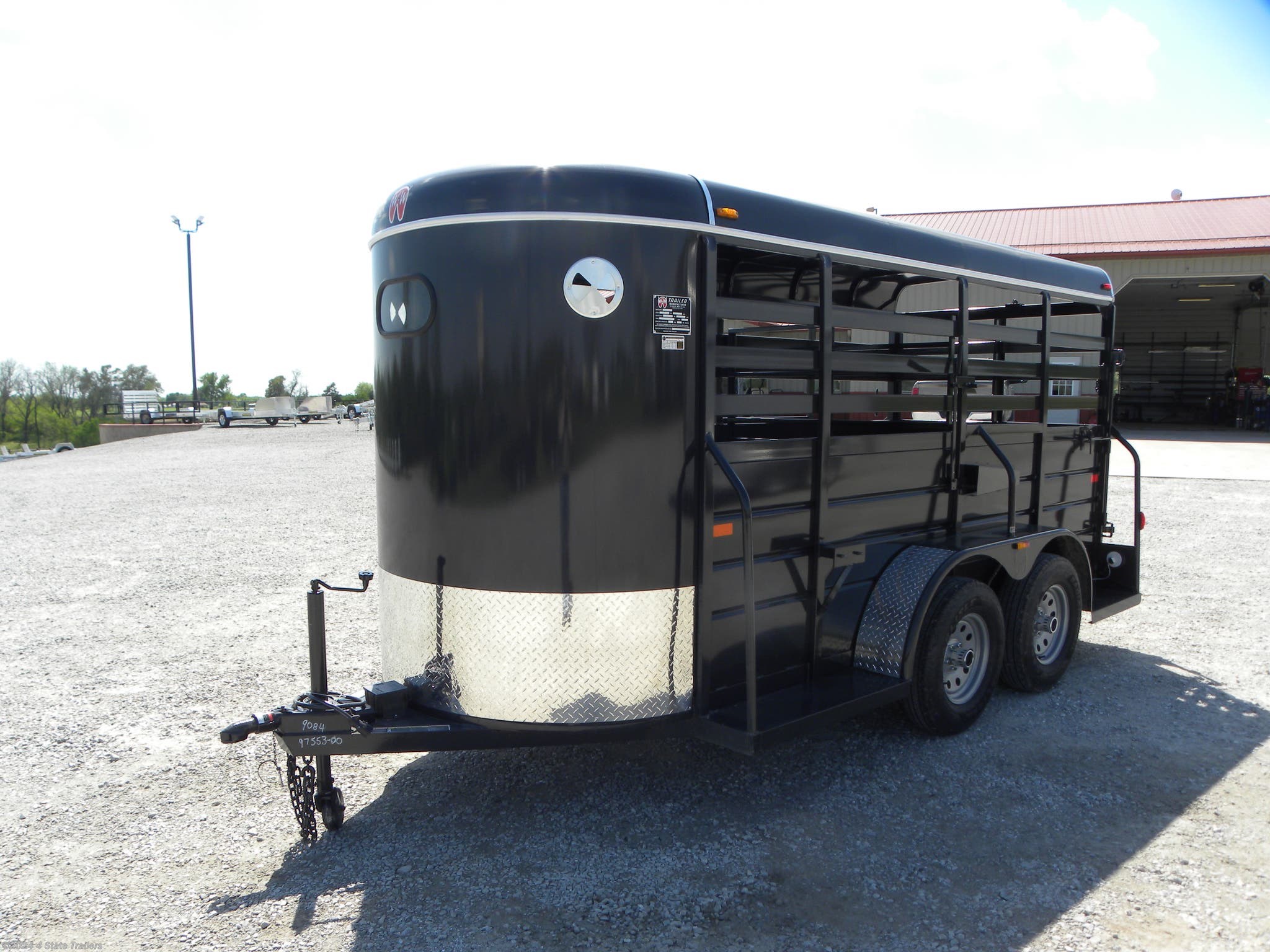
Ww horse trailer wiring diagram Idea
Home » Trend » Ww horse trailer wiring diagram Idea
Your Ww horse trailer wiring diagram images are ready. Ww horse trailer wiring diagram are a topic that is being searched for and liked by netizens today. You can Download the Ww horse trailer wiring diagram files here. Find and Download all free vectors.
If you’re searching for ww horse trailer wiring diagram pictures information linked to the ww horse trailer wiring diagram interest, you have come to the ideal blog. Our site frequently provides you with hints for downloading the maximum quality video and picture content, please kindly hunt and locate more informative video content and graphics that match your interests.
Ww Horse Trailer Wiring Diagram. From there, they will run the standard wire colors to the trailer lights, brakes and battery. In this article, we also have variation of figures available. This report will be discussing horse trailer wiring diagram.what are the advantages of knowing these understanding? This ww trailer wiring diagram version is more appropriate for sophisticated trailers and rvs.
 Wiring Diagram For Horse Trailer POLITIKHANCUSS From politikhancuss.blogspot.com
Next, check the brake controller wiring. It can be used for how to rewire a utility trailer, boat trailer and others. Standard electrical connector wiring diagram. 20 may 2020 at 4:04 pm good stuff ft. A first look at the circuit diagram may be confusing, however, if you can read a subway map, search for schematics. If there is no red or blue wire and there is both a black & a white wire, normally, the black will be brakes and the white ground.
As the name implies, they use four wires to carry out the vital lighting functions.
Not all trailers/vehicles are wired to this standard. A first look at the circuit diagram may be confusing, however, if you can read a subway map, search for schematics. White pin for the ground. Of the wiring connection is located under the trailer, at the axle, where the magnet wires exit the brake. If there is a bad ground connection the trailer brakes will not work. Here we have 9 images about 7 pin trailer wiring diagram trailer side including images, pictures, models, photos, etc.
 Source: ni3-08.blogspot.com
It represents the electric powered circuits elements as easy styles, with all the true power and… 2003 toyota tacoma trailer wiring diagram april 28, 2021 Every diagram i have looked at have blue wires for the brakes. 4 pin trailer wiring diagram. 7 wire trailer circuit, 6 wire trailer circuit, 4 wire trailer circuit and other trailer wiring diagrams. White pin for the ground.
 Source: sometimesawitch.blogspot.com
White pin for the ground. Below is the generic schematic of how the wiring goes. Of the wiring connection is located under the trailer, at the axle, where the magnet wires exit the brake. 7 wire trailer circuit, 6 wire trailer circuit, 4 wire trailer circuit and other trailer wiring diagrams. Collection of horse trailer wiring diagram.
 Source: ni3-08.blogspot.com
The truck has a new controller and it is not registering when the trailer is connected which means that we have it wrong somehow. Collection of horse trailer wiring diagram. The trailer wiring diagram shows this wire going to all the lights and brakes. Standard wiring pictured below, viewed from the rear of connector (where wires attach). As the name implies, they use four wires to carry out the vital lighting functions.
 Source: cars-wiringdiagram.blogspot.com
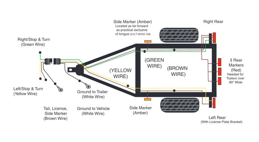
Below is the generic schematic of how the wiring goes. Trailer is 2003 model and box cover appears too loose so i tend to think they�re right. The four wires control the turn signals, brake lights and taillights or running lights. Right turn signal / stop light (green), left turn signal / stop light (yellow), taillight / license / side marker (brown) and a ground (white). Horse trailers may use the center pin for 12v hot lead, r.v.
 Source: politikhancuss.blogspot.com
A first look at the circuit diagram may be confusing, however, if you can read a subway map, search for schematics. Sever the blue brake output wire, leaving enough room to splice it back together when testing is done and then apply the manual slide. The red and brown are from the trailer end, they come right out of the hub of the front wheels (2 axle) so they must be for the brakes. S trailer brakes blue lt left turn/brake light yellow rt right turn/brake light green a accessory red the most common variances on this diagram will be the (blue/brake) & (red/acc.) wires will be inverted. It shows the parts of the circuit as streamlined forms, and also the power as well as signal links between the gadgets.

4 pin trailer wiring diagram. Over time, the outer covering of the wires will become brittle and crack/ break, exposing the wires, allowing the wires to short circuit. Brown pin for unwanted markers, tail lamps, and running lights. Trailers use the center pin for electric brakes. White pin for the ground.
 Source: wiringideas.blogspot.com
4 way flat molded connectors allow basic hookup for three lighting functions; Standard wiring pictured below, viewed from the rear of connector (where wires attach). The trailer wiring diagram shows this wire going to all the lights and brakes. The use of an electrical circuit tester is recommended to ensure proper match of vehicle’s wiring to the trailer’s wiring. Next, check the brake controller wiring.
 Source: trailer-wiring-diagram.com
From there, they will run the standard wire colors to the trailer lights, brakes and battery. The truck has a new controller and it is not registering when the trailer is connected which means that we have it wrong somehow. Next, check the brake controller wiring. White pin for the ground. I recently added an 3/4 tonne sankey to my fleet….
 Source: cars-wiringdiagram.blogspot.com
4 way flat molded connectors allow basic hookup for three lighting functions; It can be used for how to rewire a utility trailer, boat trailer and others. 20 may 2020 at 4:04 pm good stuff ft. 4 pin trailer wiring diagram. 4 way flat molded connectors allow basic hookup for three lighting functions;
 Source: quentinspeaks.blogspot.com
This short video is about trailer brakes, electric brakes and wiring. Below is the generic schematic of how the wiring goes. From there, they will run the standard wire colors to the trailer lights, brakes and battery. In this article, we also have variation of figures available. Brown pin for unwanted markers, tail lamps, and running lights.

Using a circuit tester, like item # 40376, you should get output to the trailer brakes. It symbolizes the power circuits factors as simple styles, with the true power and terrain contacts between them as coloured sectors. 7 wire trailer circuit, 6 wire trailer circuit, 4 wire trailer circuit and other trailer wiring diagrams. Such as png, jpg, animated gifs, pic art, logo, black and white, transparent, etc about 7 pin trailer wiring diagram trailer side. A wiring diagram is a simplified traditional photographic depiction of an electrical circuit.
 Source: cars-wiringdiagram.blogspot.com
It can be used for how to rewire a utility trailer, boat trailer and others. 20 may 2020 at 4:04 pm good stuff ft. From there, they will run the standard wire colors to the trailer lights, brakes and battery. In this article, we also have variation of figures available. It also talks about electric brake controller.thanks for watching !
 Source: pinterest.com
From there, they will run the standard wire colors to the trailer lights, brakes and battery. In electric powered design, a ww horse trailer wiring diagram is usually employed being an example to describe the electrical circuits to individuals unfamiliar with electric engineering. A simple closed system while it�s never a good idea to dive into a wiring project blind, trailer wiring is actually very simple to work on and troubleshoot. Trailer is 2003 model and box cover appears too loose so i tend to think they�re right. Click image to see an enlarged view electrical diagram see more ideas about trailer, trailer wiring diagram, utility trailer.
 Source: wiringdiagramall.blogspot.com
This vehicle is designed not only to travel one location to another but also to take heavy loads. Such as png, jpg, animated gifs, pic art, logo, black and white, transparent, etc about 7 pin trailer wiring diagram trailer side. The black (12v) and blue (electric brakes) may be reversed to suit trailer. Trailer wiring diagrams 4 way systems. From there, they will run the standard wire colors to the trailer lights, brakes and battery.
 Source: trailer-wiring-diagram.com
As the name implies, they use four wires to carry out the vital lighting functions. Every diagram i have looked at have blue wires for the brakes. This report will be discussing horse trailer wiring diagram.what are the advantages of knowing these understanding? In electric powered design, a ww horse trailer wiring diagram is usually employed being an example to describe the electrical circuits to individuals unfamiliar with electric engineering. The use of an electrical circuit tester is recommended to ensure proper match of vehicle’s wiring to the trailer’s wiring.
 Source: cars-wiringdiagram.blogspot.com
The four wires control the turn signals, brake lights and taillights or running lights. I recently added an 3/4 tonne sankey to my fleet…. It symbolizes the power circuits factors as simple styles, with the true power and terrain contacts between them as coloured sectors. If there is a bad ground connection the trailer brakes will not work. This type of connector is normally found on utvs, atvs and trailers that do not have their own braking system.
 Source: quentinspeaks.blogspot.com
Trailers use the center pin for electric brakes. The diagram below shows the proper way to wire the connector to your trailer or vehicle. Brown pin for unwanted markers, tail lamps, and running lights. Such as png, jpg, animated gifs, pic art, logo, black and white, transparent, etc about 7 pin trailer wiring diagram trailer side. This diagram shows the colors of a basic trailer wiring setup as well as what each wire is supposed to be connected to.
 Source: sitzone.blogspot.com
A first look at the circuit diagram may be confusing, however, if you can read a subway map, search for schematics. It can be used for how to rewire a utility trailer, boat trailer and others. Should know by the end of the day. A first look at the circuit diagram may be confusing, however, if you can read a subway map, search for schematics. Here we have 9 images about 7 pin trailer wiring diagram trailer side including images, pictures, models, photos, etc.
This site is an open community for users to submit their favorite wallpapers on the internet, all images or pictures in this website are for personal wallpaper use only, it is stricly prohibited to use this wallpaper for commercial purposes, if you are the author and find this image is shared without your permission, please kindly raise a DMCA report to Us.
If you find this site serviceableness, please support us by sharing this posts to your preference social media accounts like Facebook, Instagram and so on or you can also bookmark this blog page with the title ww horse trailer wiring diagram by using Ctrl + D for devices a laptop with a Windows operating system or Command + D for laptops with an Apple operating system. If you use a smartphone, you can also use the drawer menu of the browser you are using. Whether it’s a Windows, Mac, iOS or Android operating system, you will still be able to bookmark this website.
Category
Related By Category
- Predator 670 engine wiring diagram Idea
- Frsky x8r wiring diagram information
- Pioneer ts wx130da wiring diagram Idea
- Johnson 50 hp wiring diagram Idea
- Kohler voltage regulator wiring diagram Idea
- Johnson 50 hp outboard wiring diagram information
- Kti hydraulic remote wiring diagram Idea
- Pyle plpw12d wiring diagram information
- Tx9600ts wiring diagram information
- Lifan 50cc wiring diagram information