Wound rotor motor wiring diagram information
Home » Trend » Wound rotor motor wiring diagram information
Your Wound rotor motor wiring diagram images are available in this site. Wound rotor motor wiring diagram are a topic that is being searched for and liked by netizens now. You can Download the Wound rotor motor wiring diagram files here. Find and Download all royalty-free vectors.
If you’re looking for wound rotor motor wiring diagram pictures information connected with to the wound rotor motor wiring diagram topic, you have visit the right site. Our website always provides you with hints for downloading the highest quality video and image content, please kindly hunt and find more enlightening video articles and graphics that fit your interests.
Wound Rotor Motor Wiring Diagram. The loop ends are fixed to the slip rings, and two brushes make the connection between the slip rings and the external circuit. Terminal markings and internal wiring diagrams single phase and polyphase motors meeting nema standards see fig. The dc shunt motor construction is the same as any type of dc motor this motor can be constructed with the basic parts like field windings stator a commutator and an armature rotor. As 183 wiring diagram with switch.
 ☑ Define Wound Rotor Induction Motor From amicalegc-0607.blogspot.com
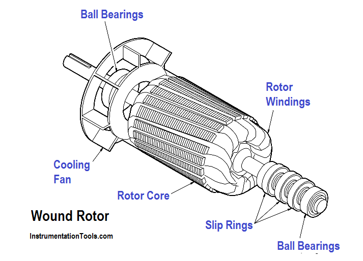
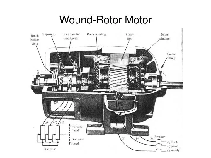
In contrast, a traditional induction motor (aka “squirrel cage motor”) has windings that. Through examining figure 2, it becomes clear why these motors are known as “series wound” dc motors; In wound rotor motors, the rotor is “wound” with wire similar to the stator, with their terminal ends connected to 3 slip rings on the output shaft. These slip rings are attached to brushes and variable power resistor banks, where operators can change the speed of the motor by varying the resistance through the rotor coils. Dc shunt motor circuit diagram. Dc shunt motor construction circuit types of dc motor shunt series diagram of the dc shunt motor types of dc motor shunt series.
Rotor magnetic field and stator magnetic field and make the stator field rotating.
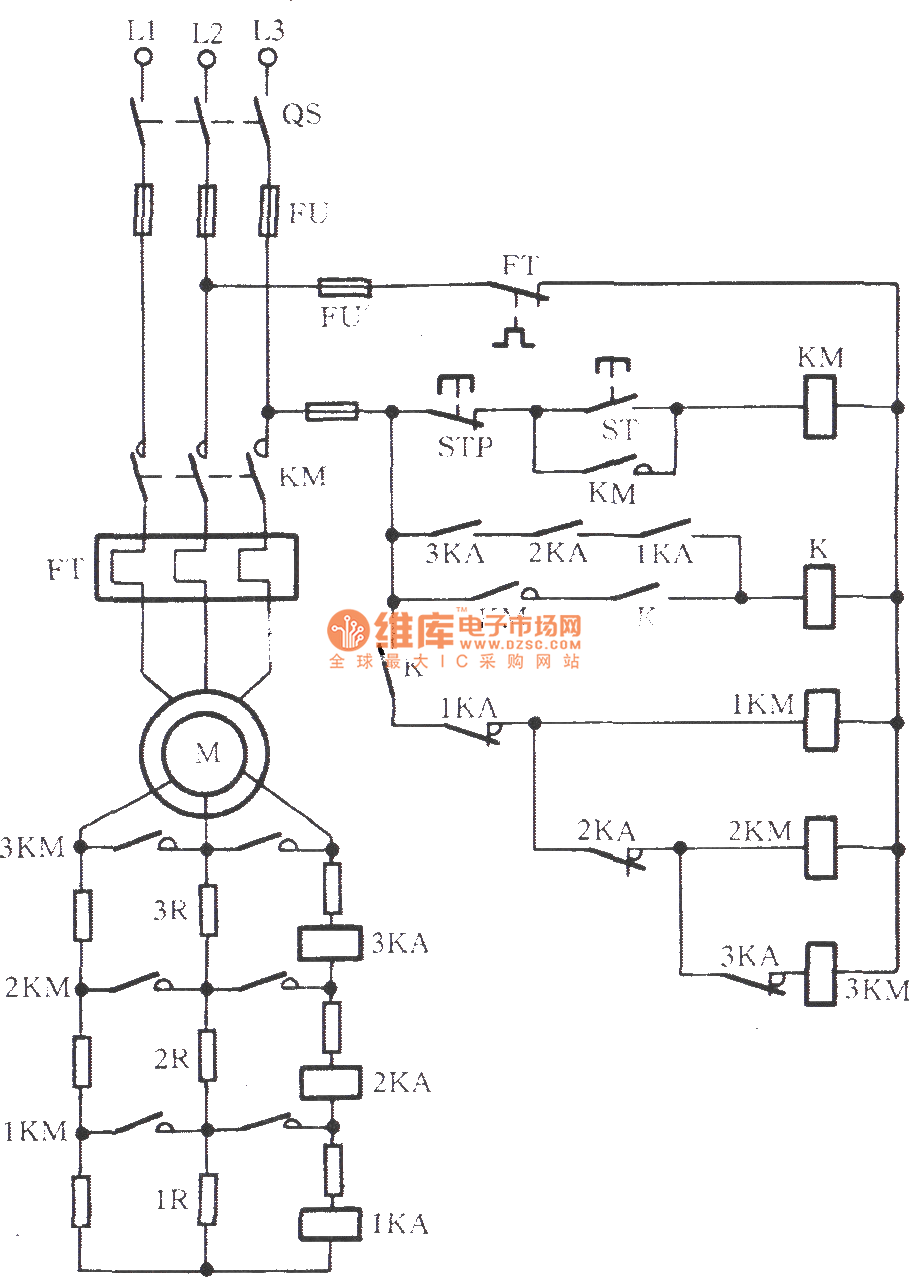
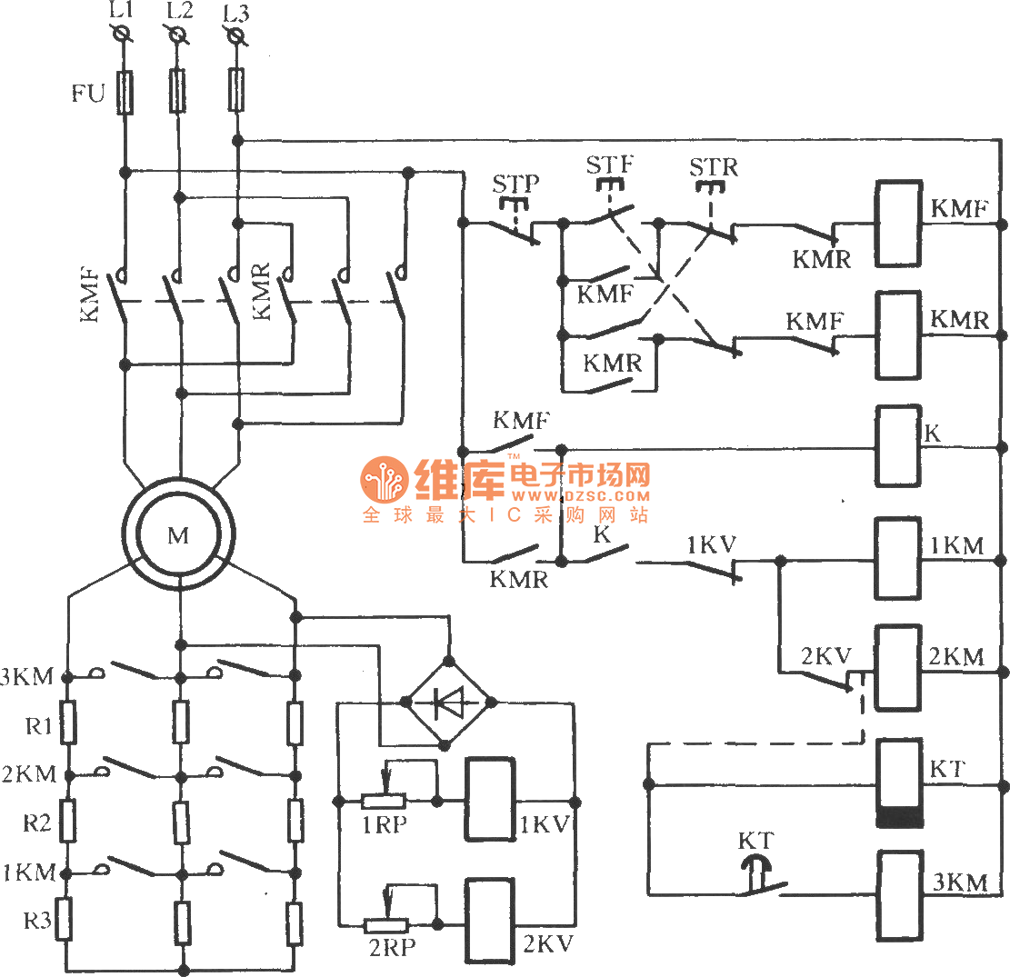
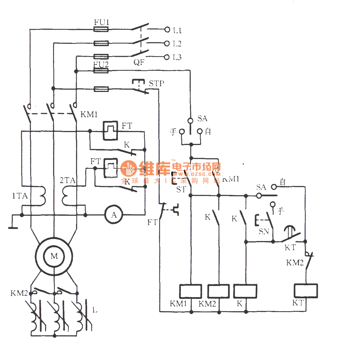
What makes the wound rotor motor a unique induction machine is its rotor. Adjusting the resistance allows control of the speed/torque characteristic of the motor. Wound rotor induction motor is used in applications which require smooth start and adjustable speed. Ac motor diagrams basic stator and rotor operation an ac motor converts electric energy into mechanical energy. The model is based on standard dq modeling theory and is set in the stationary reference you can attach mechanical loads sensors or motion controllers to the motor through this pin. A wound rotor induction motor has a stator like a squirrel cage induction motor, but a rotor with insulated windings brought out via slip rings and brushes.
 Source: industrial-electronics.com
Their field winding is powered by the dc power supply and is wired in series with the armature winding. Rotor magnetic field and stator magnetic field and make the stator field rotating. 12 squirrel cage induction motor circuit diagram. Dc shunt motor construction circuit types of dc motor shunt series diagram of the dc shunt motor types of dc motor shunt series. The model is based on standard dq modeling theory and is set in the stationary reference you can attach mechanical loads sensors or motion controllers to the motor through this pin.
 Source: seekic.com
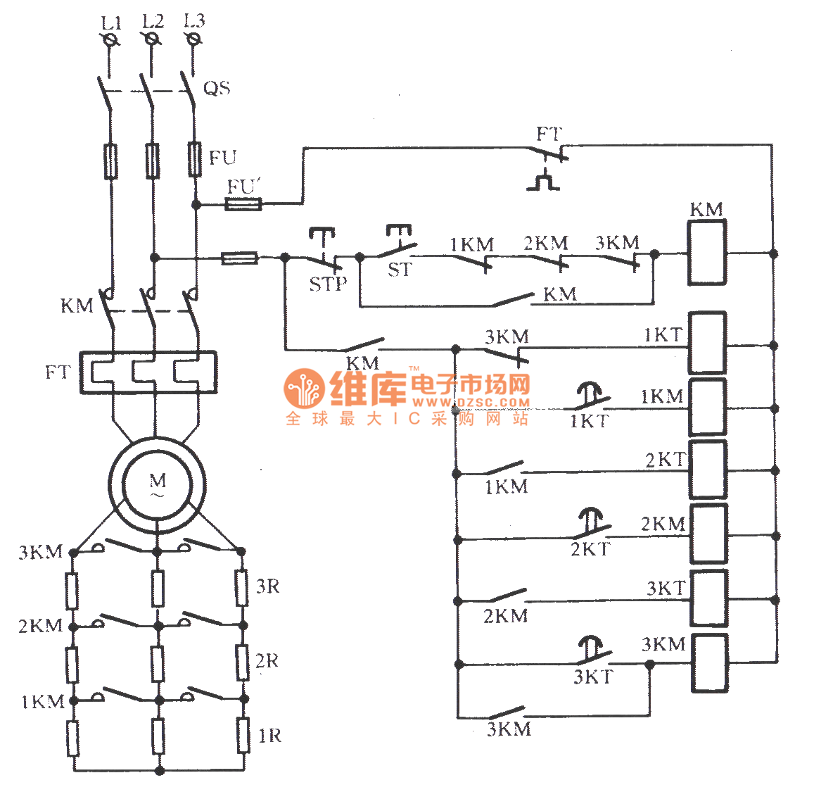
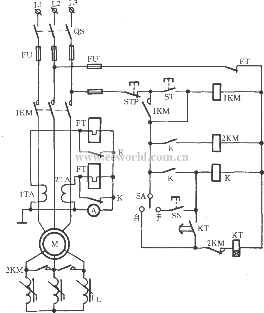
Their sole purpose is to allow resistance to be placed in series with the rotor windings while starting (figure below). Their sole purpose is to allow resistance to be placed in series with the rotor windings while starting (figure below). They are used in large pumps in water industry. Shunt wound dc motor wiring diagram wiring diagram is a simplified standard pictorial representation of an electrical circuit. Also, they incorporate brushes and slip rings.
 Source: seekic.com
The simplified circuit diagram for series wound dc motors. Motor wiring diagram d c. The loop ends are fixed to the slip rings, and two brushes make the connection between the slip rings and the external circuit. A universal electric motor is designed to operate on either alternating current or direct current (ac/dc). Wound rotor motors are also referred to as “slip ring motors.”.
 Source: wiringdiagramall.blogspot.com
Single phase induction generator self excited as a wind turbine transmission line capacitor bank connection on doubly fed construction types working isolated circuit wound rotor an simulation of farm model motor set m g control coil diagram wiring. However the frequency of the voltage is determined by the slip of the motor. Their sole purpose is to allow resistance to be placed in series with the rotor windings while starting (figure below). It is a series wound motor. Wiring diagram for squirrel cage motor wiring diagram is a simplified tolerable pictorial representation of an electrical circuit.
 Source: youtube.com
Also, they incorporate brushes and slip rings. Adjusting the resistance allows control of the speed/torque characteristic of the motor. Use the link below for the free pdf. The loop ends are fixed to the slip rings, and two brushes make the connection between the slip rings and the external circuit. April 2021 easa members can download a pdf of internal connection diagrams for free.
 Source: amicalegc-0607.blogspot.com
The below figure shows the wound rotor induction motor diagram. Slip rings are used to connect a wound rotor to external resistance to change the motor speed / torque characteristic. Adjusting the resistance allows control of the speed/torque characteristic of the motor. Typical wiring diagram for drum controller operation of a.c. However the frequency of the voltage is determined by the slip of the motor.
 Source: instrumentationtools.com
Also, they incorporate brushes and slip rings. This edition of easa internal connection diagrams contains significantly more connections than the previous version (1982), as well as improved templates for drawing connection diagrams. A universal electric motor is designed to operate on either alternating current or direct current (ac/dc). Wound rotor induction motor is also used in fans, blowers and mixers. Dc shunt motor construction circuit types of dc motor shunt series diagram of the dc shunt motor types of dc motor shunt series.
 Source: industrial-electronics.com
Single phase induction generator self excited as a wind turbine transmission line capacitor bank connection on doubly fed construction types working isolated circuit wound rotor an simulation of farm model motor set m g control coil diagram wiring. Adjusting the resistance allows control of the speed/torque characteristic of the motor. Through examining figure 2, it becomes clear why these motors are known as “series wound” dc motors; Dc shunt motor circuit diagram. Notice how the field winding is connected in series to the rotor assembly.
 Source: emadrlc.blogspot.com
Shunt wound dc motor wiring diagram wiring diagram is a simplified standard pictorial representation of an electrical circuit it shows the components of the circuit. As 183 wiring diagram with switch. The below figure shows the wound rotor induction motor diagram. Terminal markings and internal wiring diagrams single phase and polyphase motors meeting nema standards see fig. Adjusting the resistance allows control of the speed/torque characteristic of the motor.
 Source: easywiring.info
Posted by margaret byrd posted on july 25 2021. Shunt wound dc motor wiring diagram wiring diagram is a simplified standard pictorial representation of an electrical circuit. Early tesla / westinghouse 2 phase wound rotor motor In this wiring setup, there are 4 windings in series between any two line leads. The model is based on standard dq modeling theory and is set in the stationary reference you can attach mechanical loads sensors or motion controllers to the motor through this pin.
 Source: amicalegc-0607.blogspot.com
In the rotor circuit the speed of the motor can be reduced. In wound rotor motors, the rotor is “wound” with wire similar to the stator, with their terminal ends connected to 3 slip rings on the output shaft. Early tesla / westinghouse 2 phase wound rotor motor Basic circuit diagram of dc motors. Their sole purpose is to allow resistance to be placed in series with the rotor windings while starting (figure below).
 Source: seekic.com
Wound rotor induction motor is also used in fans, blowers and mixers. Ac motor diagrams basic stator and rotor operation an ac motor converts electric energy into mechanical energy. How does a wound rotor motor work? In the rotor circuit the speed of the motor can be reduced. Their field winding is powered by the dc power supply and is wired in series with the armature winding.
 Source: pinterest.com
Wound rotor induction motor is used in applications which require smooth start and adjustable speed. The rotor is said to shunt the armature. The below figure shows the wound rotor induction motor diagram. Use the link below for the free pdf. In this wiring setup, there are 4 windings in series between any two line leads.
 Source: slideserve.com
A universal electric motor is designed to operate on either alternating current or direct current (ac/dc). A wound rotor induction motor has a stator like a squirrel cage induction motor, but a rotor with insulated windings brought out via slip rings and brushes. Notice how the field winding is connected in series to the rotor assembly. Single phase induction generator self excited as a wind turbine transmission line capacitor bank connection on doubly fed construction types working isolated circuit wound rotor an simulation of farm model motor set m g control coil diagram wiring. 3 phase induction motor diagram.
 Source: tonetastic.info
Rotor magnetic field and stator magnetic field and make the stator field rotating. Typical wiring diagram for drum controller operation of a.c. These slip rings are attached to brushes and variable power resistor banks, where operators can change the speed of the motor by varying the resistance through the rotor coils. Slip rings are used to connect a wound rotor to external resistance to change the motor speed / torque characteristic. 12 squirrel cage induction motor circuit diagram.
 Source: favpng.com
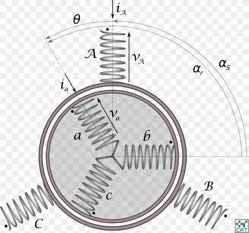
The rotor is said to shunt the armature. Generator coil diagram wiring todays rh 18 single phase stator png image transpa free on seekpng. Dc shunt motor circuit diagram. Wound rotor induction motor is also used in fans, blowers and mixers. Notice that the single wire loop is connected to a resistor and together they form a closed loop.
 Source: seekic.com
As 183 wiring diagram with switch. Typical wiring diagram for drum controller operation of a.c. Shunt wound dc motor wiring diagram wiring diagram is a simplified standard pictorial representation of an electrical circuit. A wound rotor induction motor has a stator like a squirrel cage induction motor, but a rotor with insulated windings brought out via slip rings and brushes. Their sole purpose is to allow resistance to be placed in series with the rotor windings while starting (figure below).
 Source: seekic.com
These slip rings are attached to brushes and variable power resistor banks, where operators can change the speed of the motor by varying the resistance through the rotor coils. However, no power is applied to the slip rings. 12 squirrel cage induction motor circuit diagram. In wound rotor motors, the rotor is “wound” with wire similar to the stator, with their terminal ends connected to 3 slip rings on the output shaft. Wound rotor induction motor is used in applications which require smooth start and adjustable speed.
This site is an open community for users to submit their favorite wallpapers on the internet, all images or pictures in this website are for personal wallpaper use only, it is stricly prohibited to use this wallpaper for commercial purposes, if you are the author and find this image is shared without your permission, please kindly raise a DMCA report to Us.
If you find this site value, please support us by sharing this posts to your favorite social media accounts like Facebook, Instagram and so on or you can also bookmark this blog page with the title wound rotor motor wiring diagram by using Ctrl + D for devices a laptop with a Windows operating system or Command + D for laptops with an Apple operating system. If you use a smartphone, you can also use the drawer menu of the browser you are using. Whether it’s a Windows, Mac, iOS or Android operating system, you will still be able to bookmark this website.
Category
Related By Category
- Predator 670 engine wiring diagram Idea
- Frsky x8r wiring diagram information
- Pioneer ts wx130da wiring diagram Idea
- Johnson 50 hp wiring diagram Idea
- Kohler voltage regulator wiring diagram Idea
- Johnson 50 hp outboard wiring diagram information
- Kti hydraulic remote wiring diagram Idea
- Pyle plpw12d wiring diagram information
- Tx9600ts wiring diagram information
- Lifan 50cc wiring diagram information