Wiring diagram for alternator with external voltage regulator Idea
Home » Trend » Wiring diagram for alternator with external voltage regulator Idea
Your Wiring diagram for alternator with external voltage regulator images are ready. Wiring diagram for alternator with external voltage regulator are a topic that is being searched for and liked by netizens today. You can Download the Wiring diagram for alternator with external voltage regulator files here. Get all royalty-free vectors.
If you’re searching for wiring diagram for alternator with external voltage regulator images information connected with to the wiring diagram for alternator with external voltage regulator keyword, you have pay a visit to the ideal site. Our website frequently gives you hints for seeking the highest quality video and picture content, please kindly search and locate more informative video content and images that match your interests.
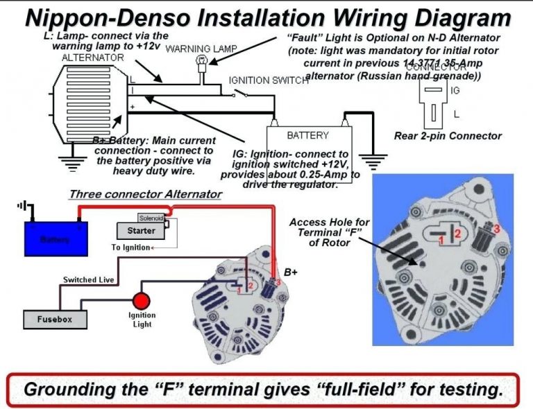
Wiring Diagram For Alternator With External Voltage Regulator. Wiring diagram for alternator with external voltage regulator. First, you can�t run to the same side, since with the 12 volt conversion, we are going to use. As stated earlier, the traces at a external voltage regulator wiring diagram signifies wires. Alternator voltage regulation 101 with wiring diagrams in the garage carparts com regulator troubleshooting ford and an ext install truck enthusiasts forums how to.
 External Voltage Regulator Wiring Diagram — UNTPIKAPPS From untpikapps.com
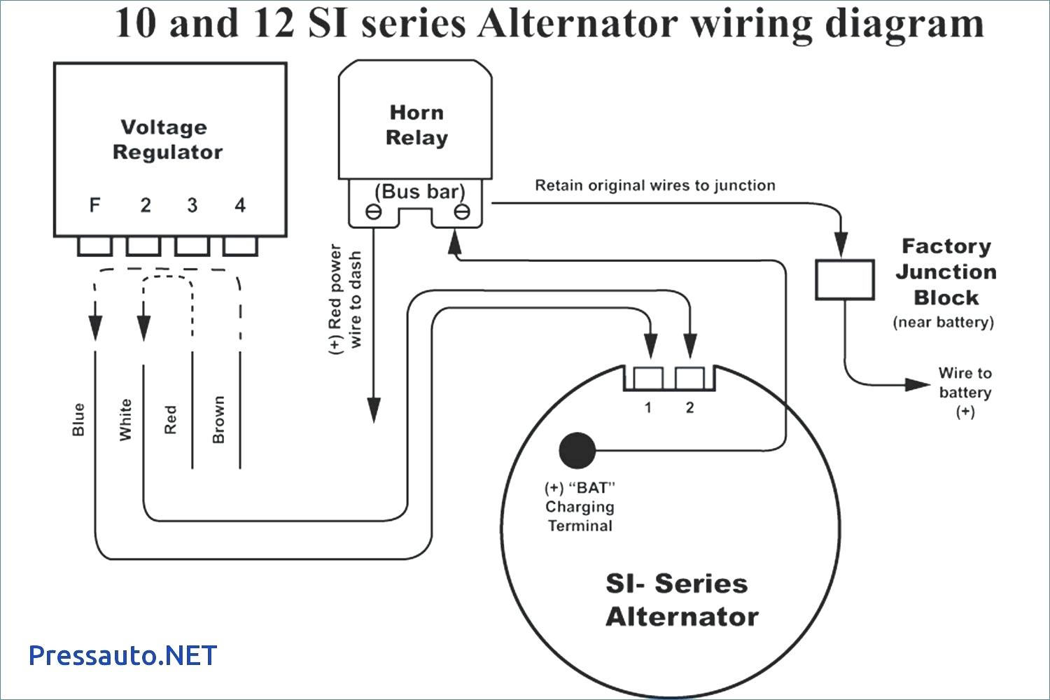
Diagram gm external regulator wiring full version hd quality diagramref amicideidisabilionlus it. It is intended to assist all of the typical consumer in building a proper system. When sensing the rotation of the rotor. Refer to the simple diagram below for systems with an external electromechanical voltage regulator. Wiring instructions for the early gm delco remy external regulated alternator. Alternator voltage regulation 101 with wiring diagrams in the garage carparts com regulator troubleshooting ford and an ext install truck enthusiasts forums how to.
Battery positive cable, voltage sensing wire, and ignition wire.
External regulator 3 wire ford alternator wiring diagram. Wiring diagram for alternator with external regulator wiring diagram is a simplified gratifying pictorial representation of an electrical circuit it shows the components of the circuit as simplified shapes and the gift and signal associates in the midst of the devices. Wiring diagram for alternator with external regulator. The easiest way to identify that the alternator is internally or externally regulated is to look in the engine bay for the presence of a voltage. As stated earlier, the traces at a external voltage regulator wiring diagram signifies wires. As the name indicates it regulates the amount of voltage produced from the alternator to ensure a consistent voltage to.
 Source: untpikapps.com
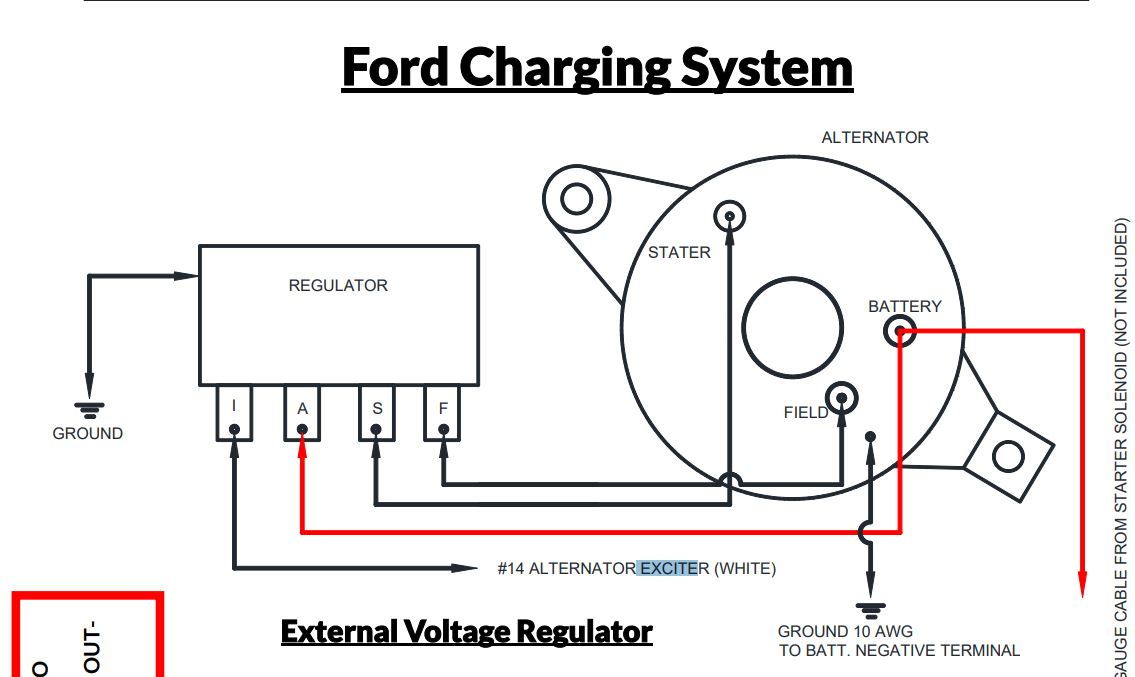
Each component should be set and connected with other parts in specific way. Also my truck is a 915 so it had the voltage regulator from the factory but this would work the same for a 92 or 93 that someone is installing an external. Ford alternator internal regulator wiring external voltage diagram. Injunction of 2 wires is generally indicated by black dot to the junction of 2 lines. A typical alternator wiring diagram with an external electromechanical voltage regulator.
 Source: autozone.com
One of the leads has a diode on it. Wiring diagram comes with numerous easy to follow wiring diagram guidelines. These instructions will probably be easy to understand and use. The easiest way to identify that the alternator is internally or externally regulated is to look in the engine bay for the presence of a voltage. For example , in case a module is powered up and it sends out a new signal of half the voltage in addition to the technician would not know this, he�d think he has a problem, as he would expect.
 Source: pinterest.com
Injunction of 2 wires is generally indicated by black dot to the junction of 2 lines. Alternator regulator troubleshooting voltage regulation 101 with wiring diagrams in the garage carparts com how to wire a gm external regulated 10dn 3 diagram seaboard marine reyhan blog bosch circuit for alternators and starters ford explorer ranger forums serious explorations 12 volt. Wiring instructions for the early gm delco remy external regulated alternator. 8sc3009 product details prestolite leece neville. Diagram gm external regulator wiring full version hd quality diagramref amicideidisabilionlus it.
 Source: 2020cadillac.com
Refer to the simple diagram below for systems with an external electromechanical voltage regulator. Refer to the simple diagram below for systems with an external electromechanical voltage regulator. The easiest way to identify that the alternator is internally or externally regulated is to look in the engine bay for the presence of a voltage. Wiring diagram will come with several easy to stick to wiring diagram instructions. Mark the area and drill holes for mounting of bolts.
 Source: sbmar.com
Step 1 install the wires to the alternate regulator. External regulator 3 wire ford alternator wiring diagram. As stated earlier, the traces at a external voltage regulator wiring diagram signifies wires. The circuit comprises three main wires: You can save this graphic file to your own device.
 Source: morphine-and-drugs.blogspot.com
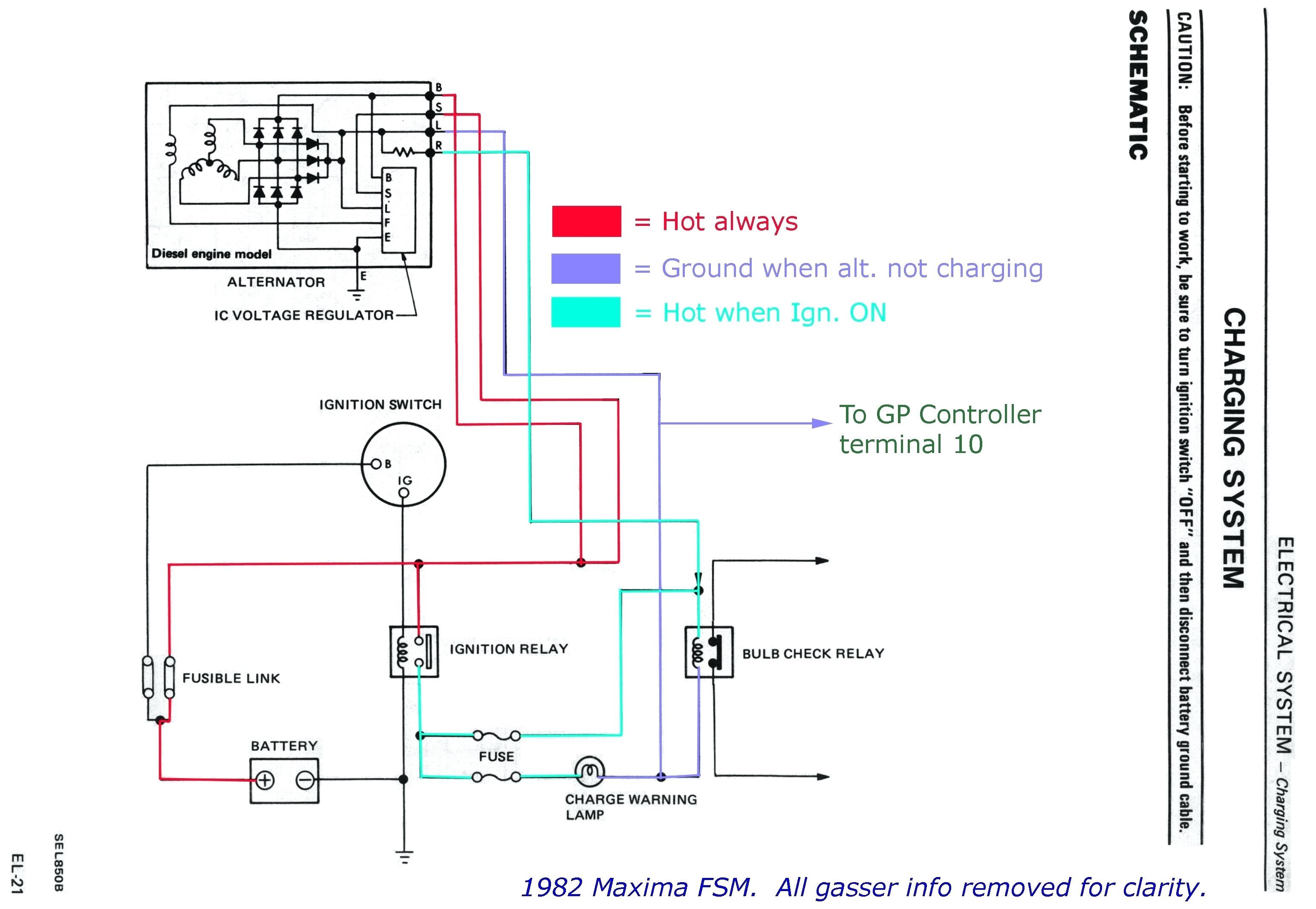
To properly read a cabling diagram, one has to learn how the components in the method operate. External regulation conversion leece neville 8mr alternator marine how to prestolite new series spool mount type 12v 65a 110 606 487 51a 494 show posts mainesail self build adjule controler 600 output wiring irv2 forums technical help with 5 wire the h a m b and motorola voltage regulators 37a 699 90a 603 content electrical s3 e figure 21 1 digital multimeter. On alternator external voltage regulator wiring diagram alternator voltage regulator electrical wiring diagram. External voltage regulator wiring diagram wiring diagram is a simplified within acceptable limits pictorial representation of an electrical circuitit shows the components of the circuit as simplified shapes and the capability and signal contacts along with the devices. Wiring instructions for the early gm delco remy external regulated alternator.
 Source: wiringdiagram.2bitboer.com
On alternator external voltage regulator wiring diagram alternator voltage regulator electrical wiring diagram. A set of wiring diagrams may be required by the electrical inspection authority to agree to link of the address to the public electrical supply system. Refer to the simple diagram below for systems with an external electromechanical voltage regulator. The early gm alternator is the 10dn series alternator and was used on gm vehicles from about 1963 1970. 3 wire alternator wiring diagram source:
 Source: wiringdiagramall.blogspot.com
Occasionally, the wires will cross. The circuit comprises three main wires: Wiring diagram will come with several easy to stick to wiring diagram instructions. External regulator 3 wire ford alternator wiring diagram. And connect the red wire to the output side of the alternator 10/32 stud, take the long wire and.
 Source: faceitsalon.com
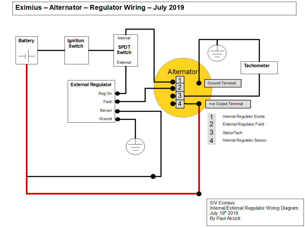
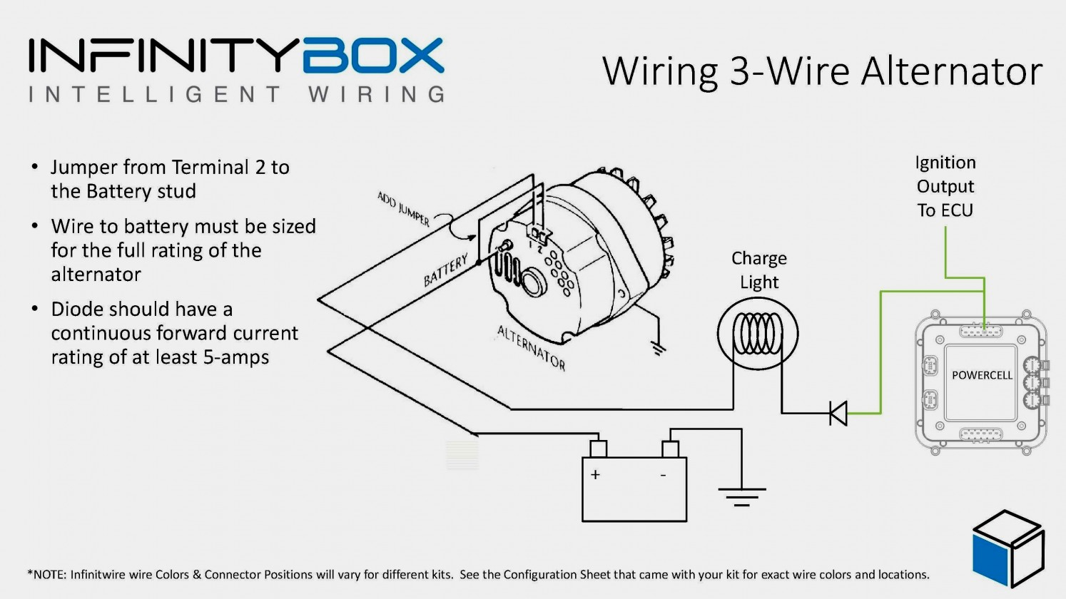
3 wire alternator wiring diagram source: Step 1 install the wires to the alternate regulator. 12 volt alternator wiring diagram. A typical alternator wiring diagram with an external electromechanical voltage regulator. On alternator external voltage regulator wiring diagram alternator voltage regulator electrical wiring diagram.
 Source: sailingeximius.com
Wiring diagram comes with numerous easy to follow wiring diagram guidelines. I am going to put it back as it should be wired. It is intended to assist all of the typical consumer in building a proper system. One of the leads has a diode on it. Connect the blue and green wirings.
Source: forum.ih8mud.com
Alternator external voltage regulator wiring diagram. You can save this graphic file to your own device. Each component should be set and connected with other parts in particular. I am going to put it back as it should be wired. Refer to the simple diagram below for systems with an external electromechanical voltage regulator.
 Source: 2020cadillac.com
As the name indicates it regulates the amount of voltage produced from the alternator to ensure a consistent voltage to. Leece neville 160 amp alternator wiring may 14 2019. And connect the red wire to the output side of the alternator 10/32 stud, take the long wire and. Check the voltage at the bat terminal on the alternator. When sensing the rotation of the rotor.
 Source: woodworkerb.com
A typical alternator wiring diagram with an external electromechanical voltage regulator. The early gm alternator is the 10dn series alternator and was used on gm vehicles from about 1963 1970. 3 wire alternator wiring diagram source: Check the voltage at the bat terminal on the alternator. Wiring diagram for alternator with external regulator.
 Source: kelvin-okl.blogspot.com
Follow wires and/or use the wiring diagram. First, you can�t run to the same side, since with the 12 volt conversion, we are going to use. The ignition input wire is attached to the engine. A set of wiring diagrams may be required by the electrical inspection authority to agree to link of the address to the public electrical supply system. External voltage regulator wiring diagram wiring diagram is a simplified within acceptable limits pictorial representation of an electrical circuitit shows the components of the circuit as simplified shapes and the capability and signal contacts along with the devices.
 Source: forums.pelicanparts.com
Wiring diagram will come with several easy to stick to wiring diagram instructions. The circuit comprises three main wires: Each component should be set and connected with other parts in specific way. However, it doesn’t imply link between the wires. The ignition input wire is attached to the engine.
 Source: turbo-mopar.com
8sc3009 product details prestolite leece neville. Wiring diagram for alternator with external voltage regulator wiring diagram line wiring diagram wiring diagram line we are make source the schematics, wiring diagrams and technical photos Alternator wiring diagram with external regulator wiring. Refer to the simple diagram below for systems with an external electromechanical voltage regulator. On alternator external voltage regulator wiring diagram alternator voltage regulator electrical wiring diagram.
 Source: wiringdiagramall.blogspot.com
Wiring diagram will come with several easy to stick to wiring diagram instructions. Battery positive cable, voltage sensing wire, and ignition wire. Connect the blue and green wirings. Install brown ignition wire the brown ignition wire 3 in diagram at right provides onoff voltage for the regulator. Check the voltage at the bat terminal on the alternator.
 Source: faceitsalon.com
It is intended to assist all of the typical consumer in building a proper system. 12 volt alternator wiring diagram. Wiring diagram for alternator with external voltage regulator. Install brown ignition wire the brown ignition wire 3 in diagram at right provides onoff voltage for the regulator. A tractor�s regulator takes the voltage provided by the battery, manages it.
This site is an open community for users to share their favorite wallpapers on the internet, all images or pictures in this website are for personal wallpaper use only, it is stricly prohibited to use this wallpaper for commercial purposes, if you are the author and find this image is shared without your permission, please kindly raise a DMCA report to Us.
If you find this site adventageous, please support us by sharing this posts to your favorite social media accounts like Facebook, Instagram and so on or you can also bookmark this blog page with the title wiring diagram for alternator with external voltage regulator by using Ctrl + D for devices a laptop with a Windows operating system or Command + D for laptops with an Apple operating system. If you use a smartphone, you can also use the drawer menu of the browser you are using. Whether it’s a Windows, Mac, iOS or Android operating system, you will still be able to bookmark this website.
Category
Related By Category
- Predator 670 engine wiring diagram Idea
- Frsky x8r wiring diagram information
- Pioneer ts wx130da wiring diagram Idea
- Johnson 50 hp wiring diagram Idea
- Kohler voltage regulator wiring diagram Idea
- Johnson 50 hp outboard wiring diagram information
- Kti hydraulic remote wiring diagram Idea
- Pyle plpw12d wiring diagram information
- Tx9600ts wiring diagram information
- Lifan 50cc wiring diagram information