Wind turbine alternator wiring diagram Idea
Home » Trend » Wind turbine alternator wiring diagram Idea
Your Wind turbine alternator wiring diagram images are available in this site. Wind turbine alternator wiring diagram are a topic that is being searched for and liked by netizens now. You can Get the Wind turbine alternator wiring diagram files here. Find and Download all free images.
If you’re searching for wind turbine alternator wiring diagram images information linked to the wind turbine alternator wiring diagram interest, you have pay a visit to the ideal site. Our website frequently provides you with hints for refferencing the highest quality video and picture content, please kindly surf and find more enlightening video articles and graphics that fit your interests.
Wind Turbine Alternator Wiring Diagram. So a quick video on hooking up a 3 phase wind turbine to the charger c. Because the wind is the best natural source that available in most places. These 3 wires can be connected to the wind turbine terminals (a, b and c terminals) in any order. (it isn’t really homemade unless it has a little baling wire and duct tape on it somewhere, now is it?) make sure to leave enough slack in the wires for the wind generator to rotate 360 degrees.
![[ZW_0882] Wiring Diagram For Wind Turbine Schematic Wiring [ZW_0882] Wiring Diagram For Wind Turbine Schematic Wiring](https://static-cdn.imageservice.cloud/7244/wind-generator-wiring-diagram-wiring-diagram-database.jpg) [ZW_0882] Wiring Diagram For Wind Turbine Schematic Wiring From filici.illuminateatx.org
[ZW_0882] Wiring Diagram For Wind Turbine Schematic Wiring From filici.illuminateatx.org
Each time a magnet passes over a coil, the coil becomes energized with electricity. However, we are adding multiple solar panels and discussing the use of power distribution panels. So a quick video on hooking up a 3 phase wind turbine to the charger c. The alternator has two 12 inch diameter rotors that each have 12 neodymium disk magnets measuring 1.47 inche in diameter and.6 inches thick. Turn the breaker switch on the controller to the stop position. Here is a diy project for wind turbine alternator.
Charge controller wiring diagram for diy wind turbine or solar panels:
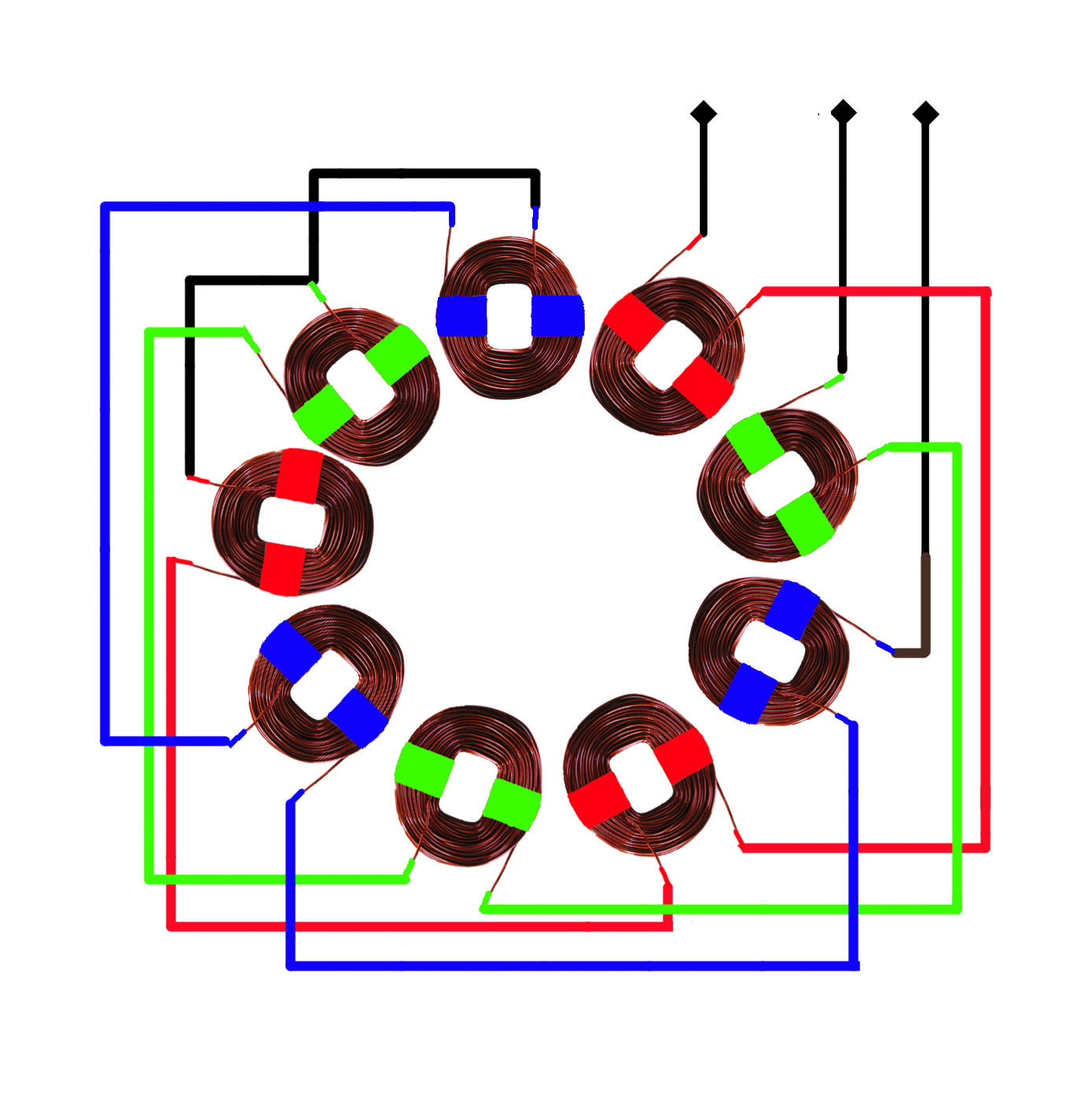
It consists of a wind turbine driving a permanent magnet alternator and operates at variable speed. It consists of a wind turbine driving a permanent magnet alternator and operates at variable speed. Alternator the plans describe how to build a permanent magnet alternator. In a 3 phase alternator, coils are wired together in 3 separate groups. On top of this pole we attached a piece of iron pipe. The alternator wiring the starting point was to choose the alternator and use the power/rpm curve for the alternator to then design the blades.
 Source: manuals.colemanair.us
More infomation can be found at ecoelementals.co.uk.thanks for looking! The change in direction of the electron flow is a result of the alternating magnet pole (north, south). Alternator demo wiring, connection to battery, capacitors,. 120 degree phase separation mistake. In addition, the ability to stabilize and maintain optimal power is always guaranteed.
 Source: pinterest.co.uk
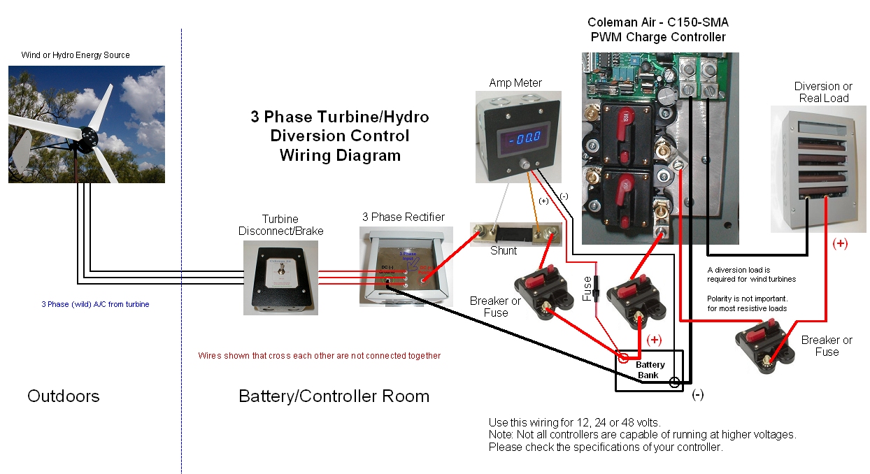
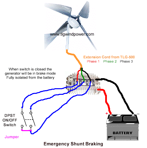
I have had lots of questions about what wires go were on our 3 phase wind turbines. Phase wire from powermax+ to the controller. The image above shows the recommended wiring diagram for a 3 phase wind turbine or water hydro. Alternator the plans describe how to build a permanent magnet alternator. It consists of a wind turbine driving a permanent magnet alternator and operates at variable speed.
 Source: pinterest.com
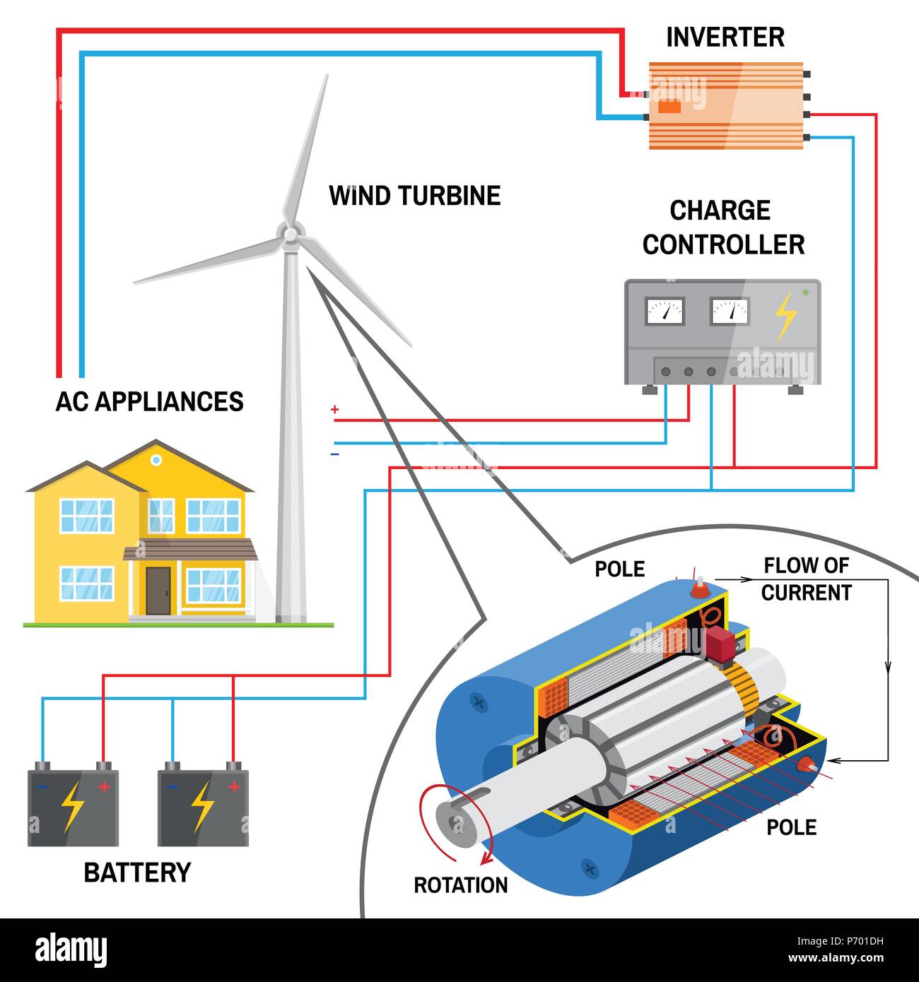
Wind turbine alternator price for popular power: Essentially this choice only affects the size of wire and the number of turns per coil. In a 1 phase alternator, coils are all wired together. This diagram shows the basic setup for those who wish to build their own wind or solar energy project. It would take a hurricane force wind to turn a small wind turbine fast enough to even start charging a battery.
![[ZW_0882] Wiring Diagram For Wind Turbine Schematic Wiring [ZW_0882] Wiring Diagram For Wind Turbine Schematic Wiring](https://static-cdn.imageservice.cloud/7244/wind-generator-wiring-diagram-wiring-diagram-database.jpg) Source: filici.illuminateatx.org
Source: filici.illuminateatx.org
Even the start wire (lead in) and the exit wire (lead out) are separated by 2 slots as can be seen in the pics below. Wind turbine alternator price for popular power: This piece of pipe, about 30cm long, with a bearing at the bottom, will house another piece of pipe, namely the male, with the male tube having holes for bolts. In a 3 phase alternator, coils are wired together in 3 separate groups. Here is a diy project for wind turbine alternator.
 Source: solarls.blogspot.com
The alternator was actually a three phase star configuration motor which was rewired to a half series half parallel 3 phase delta configuration alternator with 42 poles. 120 degree phase separation mistake. Each time a magnet passes over a coil, the coil becomes energized with electricity. The 3 phase wiring can be smaller than the d/c wiring as each wire only carries 66% of the total current being generated by the turbine. After erecting your tower, make sure that batteries are connected tightly and correctly to the controller, and then

In addition, the ability to stabilize and maintain optimal power is always guaranteed. More infomation can be found at ecoelementals.co.uk.thanks for looking! Essentially this choice only affects the size of wire and the number of turns per coil. Wind generator has common small power ranges as follows: In a 1 phase alternator, coils are all wired together.
 Source: brighthubengineering.com
In a 1 phase alternator, coils are all wired together. In a 3 phase alternator, coils are wired together in 3 separate groups. This narrow tube is threaded inside the wider tube, which is then attached to the recycled alternator. (it isn’t really homemade unless it has a little baling wire and duct tape on it somewhere, now is it?) make sure to leave enough slack in the wires for the wind generator to rotate 360 degrees. The energy produced by wind turbines depends on the swept area more than it does on the alternator maximum output.
 Source: in.pinterest.com
Wind turbine alternator price for popular power: Between the rotors is the stator consisting of 9 coils of awg #20 wire, 200 turns each. These 3 wires can be connected to the wind turbine terminals (a, b and c terminals) in any order. Phase wire from powermax+ to the controller. Essentially this choice only affects the size of wire and the number of turns per coil.
 Source: alamy.com
The energy produced by wind turbines depends on the swept area more than it does on the alternator maximum output. In addition, the ability to stabilize and maintain optimal power is always guaranteed. The characteristic of the system depends on the wind turbine, the alternator, and the system configuration. It would take a hurricane force wind to turn a small wind turbine fast enough to even start charging a battery. In a 3 phase alternator, coils are wired together in 3 separate groups.
 Source: faceitsalon.com
Here is a very similar diagram as found on page 6; However, we are adding multiple solar panels and discussing the use of power distribution panels. In a 3 phase alternator, coils are wired together in 3 separate groups. The wind turbine can be operating between a wind speed of 14 km/hr to 90 km/hr. If the electrical load does not match the wind turbine, the performance of.
 Source: endless-sphere.com
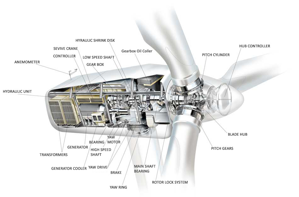
Phase wire from powermax+ to the controller. The change in direction of the electron flow is a result of the alternating magnet pole (north, south). The alternator is connected to a battery bank via rectifier. These 3 wires can be connected to the wind turbine terminals (a, b and c terminals) in any order. The wind turbine is designed to use the speed and power of wind and convert it into electrical energy.
 Source: renewableenergyhub.co.uk
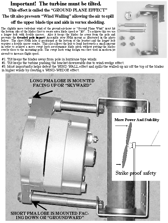
Turn the breaker switch on the controller to the stop position. Attach the positive and negative wires to the alternator and secure them to the bracket and along the tower with zip ties, baling wire, or duct tape. This diagram shows the basic setup for those who wish to build their own wind or solar energy project. The image above shows the recommended wiring diagram for a 3 phase wind turbine or water hydro. This piece of pipe, about 30cm long, with a bearing at the bottom, will house another piece of pipe, namely the male, with the male tube having holes for bolts.
 Source: pinterest.com
After erecting your tower, make sure that batteries are connected tightly and correctly to the controller, and then Here is a diy project for wind turbine alternator. A direct connection turbine turbine to the alternator could avoid the friction of the inconvenience caused by the belt or belts in the transmission if not for the need to multiply the speed of the alternator, which further aggravates the problem of effort, because to achieve to obtain the minimum number of rotations required for the production of electricity by the alternator, which. 542 x 342 jpeg 35kb, wind turbine charge controller reuk.co.uk. Phase wire from powermax+ to the controller.
 Source: pinterest.de
On the d/c side, each wire (two wires) carries 100% of the total current (what comes in, must go out.) see our wire size calculatorfor more information about wire size. 728 x 546 jpeg 64kb, wiring diagram 3 phase wind turbine wind turbine oil leak 768 x 1024 jpeg 293kb, green power: With this kind of an illustrative manual, you’ll be capable of troubleshoot, prevent, and total your tasks easily. The alternator wiring the starting point was to choose the alternator and use the power/rpm curve for the alternator to then design the blades. Alternator demo wiring, connection to battery, capacitors,.
 Source: tlgwindpower.com
Along with multiple solar panels wired in parallel, terminated via a standard a/c sub panel. Phase wire from powermax+ to the controller. In addition, the ability to stabilize and maintain optimal power is always guaranteed. 728 x 546 jpeg 64kb, wiring diagram 3 phase wind turbine wind turbine oil leak 768 x 1024 jpeg 293kb, green power: Wind generator has common small power ranges as follows:
 Source: researchgate.net
So a quick video on hooking up a 3 phase wind turbine to the charger c. The image above shows the recommended wiring diagram for a 3 phase wind turbine or water hydro. The wind turbine is designed to use the speed and power of wind and convert it into electrical energy. I have had lots of questions about what wires go were on our 3 phase wind turbines. In a 3 phase alternator, coils are wired together in 3 separate groups.
 Source: windturbineusa.com
On top of this pole we attached a piece of iron pipe. The image above shows the recommended wiring diagram for a 3 phase wind turbine or water hydro. Even the start wire (lead in) and the exit wire (lead out) are separated by 2 slots as can be seen in the pics below. Here is a diy project for wind turbine alternator. Alternator demo wiring, connection to battery, capacitors,.
 Source: lifeattheendoftheroad.wordpress.com
It contains instructions and diagrams for different types of wiring strategies as well as other things like lights, windows, and so on. Essentially this choice only affects the size of wire and the number of turns per coil. In this 3 phase 4 coil wind in 24 stator slots, we start by inserting the 1st coil and skipping 2 slots for the other 2 phases. The characteristic of the system depends on the wind turbine, the alternator, and the system configuration. Here is a very similar diagram as found on page 6;
This site is an open community for users to share their favorite wallpapers on the internet, all images or pictures in this website are for personal wallpaper use only, it is stricly prohibited to use this wallpaper for commercial purposes, if you are the author and find this image is shared without your permission, please kindly raise a DMCA report to Us.
If you find this site serviceableness, please support us by sharing this posts to your preference social media accounts like Facebook, Instagram and so on or you can also save this blog page with the title wind turbine alternator wiring diagram by using Ctrl + D for devices a laptop with a Windows operating system or Command + D for laptops with an Apple operating system. If you use a smartphone, you can also use the drawer menu of the browser you are using. Whether it’s a Windows, Mac, iOS or Android operating system, you will still be able to bookmark this website.
Category
Related By Category
- Predator 670 engine wiring diagram Idea
- Frsky x8r wiring diagram information
- Pioneer ts wx130da wiring diagram Idea
- Johnson 50 hp wiring diagram Idea
- Kohler voltage regulator wiring diagram Idea
- Johnson 50 hp outboard wiring diagram information
- Kti hydraulic remote wiring diagram Idea
- Pyle plpw12d wiring diagram information
- Tx9600ts wiring diagram information
- Lifan 50cc wiring diagram information