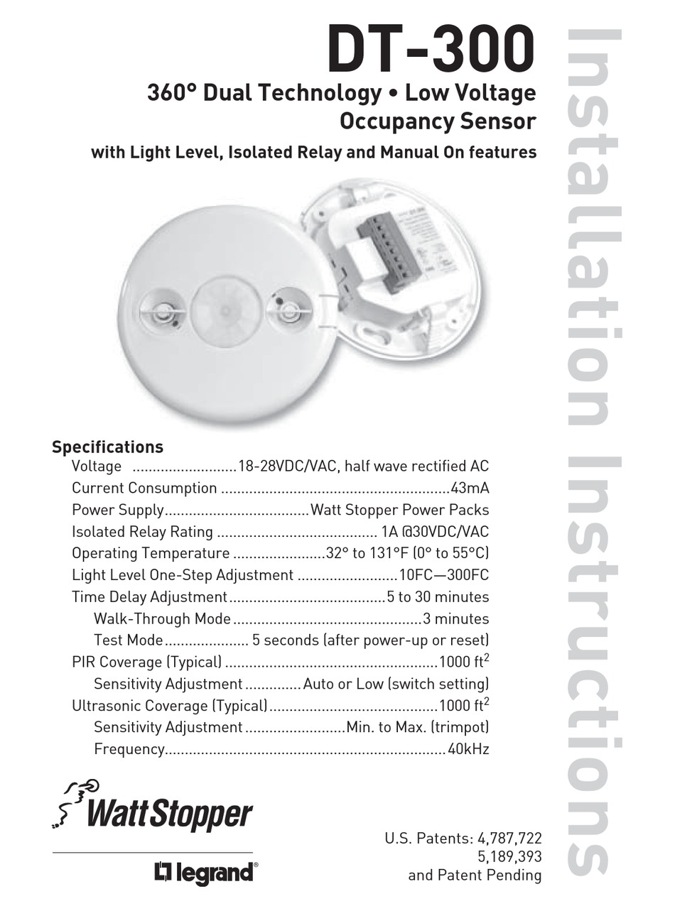
Wattstopper dw 311 wiring diagram information
Home » Trend » Wattstopper dw 311 wiring diagram information
Your Wattstopper dw 311 wiring diagram images are ready. Wattstopper dw 311 wiring diagram are a topic that is being searched for and liked by netizens now. You can Download the Wattstopper dw 311 wiring diagram files here. Download all free photos and vectors.
If you’re looking for wattstopper dw 311 wiring diagram pictures information linked to the wattstopper dw 311 wiring diagram interest, you have pay a visit to the ideal blog. Our site frequently provides you with suggestions for refferencing the highest quality video and picture content, please kindly hunt and find more informative video content and graphics that fit your interests.
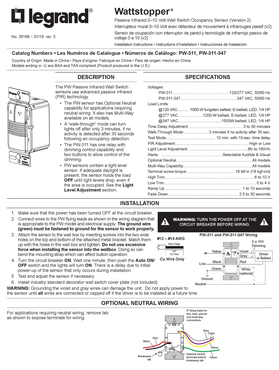
Wattstopper Dw 311 Wiring Diagram. Connect wires to the dw flying leads as shown in the wiring diagram below. 250ma 120/277vac incandescent, mlv, elv, led (fp compatible): Connect wires to the pw flying leads as shown in the wiring diagram that is appropriate to the pw model and electrical supply. Requires class 1 wiring for 0.
 WattStopper DW311I 010V Dual Tech. Wall Switchoccupancy S From lightingsupply.com
Requires class 1 wiring for 0. When wiring this way, only use 311 series sensors. After initial wiring is complete, check wiring diagram to verify power pack is wired correctly. It combines the benefits of passive infrared (pir) and ultrasonic detection technologies, and is characterized by high sensitivity to small and large movements. Wattstopper® the dw has one relay and one on/off. The elcu emergency lighting control unit allows lighting control devices for circuit to the emergency neutral lead as shown in the wiring diagram.
Operation the bz consists of a transformer and a highcurrent relay.
When wiring this way, only use 311 series sensors. Cu wire onlyattach the sensor to the wall box by inserting screws into Connect wires to the dw flying leads as shown in the wiring diagram that is appropriate to the dw model and electrical supply. Refer to the wiring diagram on the next page for the following procedures: Wattstopper® the dw has one relay and one on/off. When wiring this way, only use 311 series sensors.
 Source: lightingsupply.com
When using more sensors than this, multiple power packs are required. 250ma 120/277vac incandescent, mlv, elv, led (fp compatible): Legrand watt stopper dt 305 quick start wattstopper pw 311 installation ceiling mount occupancy sensor wt 600 1100 2200 2250 power pack 120 277v 50 60hz 24vdc 100 passive infrared wall switch lmsw 102 manual energy code. The 2 ground wires (green and green/ yellow) must be fastened to ground for the sensor to work properly. Occupancy sensors wall switches www.wattstopper.com 800.879.8585 controls & settings coverage & wiring pub.
 Source: lightingsupply.com
Make sure power has been turned off at the circuit breaker. Connect the wattstopper warranties its products to be free of defects in materials. 12� the dw dual technology wall switch sensor combines. The 2 ground wires (green and green/ yellow) must be fastened to ground for the sensor to work properly. Connect wires to the pw flying leads as shown in the wiring diagram that is appropriate to the pw model and electrical supply.
 Source: lightingsupply.com
When using more sensors than this, multiple power packs are required. The 2 ground wires (green and green/ yellow) must be fastened to ground for the sensor to work properly. When using more sensors than this, multiple power packs are required. When using more sensors than this, multiple power packs are required. To increase or decrease the lighting level.
 Source: lightingsupply.com
The ground wire (green) must be fastened to ground for the sensor to work. 250ma 120/277vac incandescent, mlv, elv, led (fp compatible): The elcu emergency lighting control unit allows lighting control devices for circuit to the emergency neutral lead as shown in the wiring diagram. For help with emergency lighting control unit from wattstopper; Connect wires to the pw flying leads as shown in the wiring diagram that is appropriate to the pw model and.
 Source: wiringdiagram.2bitboer.com
When wiring this way, only use 311 series sensors. Lmrc digital on/off/ volt dimming room controller with 1 relay and 1. Refer to the wiring diagram on the next page for the following procedures: The 2 ground wires (green and green/ yellow) must be fastened to ground for the sensor to work properly. Legrand watt stopper dt 305 quick start wattstopper pw 311 installation ceiling mount occupancy sensor wt 600 1100 2200 2250 power pack 120 277v 50 60hz 24vdc 100 passive infrared wall switch lmsw 102 manual energy code.
 Source: lightingsupply.com
Lmrc digital on/off/ volt dimming room controller with 1 relay and 1. This product can be used as a standard dimming wall switch, but also comes with both passive infrared and ultrasonic detection capibilities. 250ma 120/277vac incandescent, mlv, elv, led (fp compatible): Connect wires to the pw flying leads as shown in the wiring diagram that is appropriate to the pw model and electrical supply. Visit wiringall.comopper/com/dlm and download sales dlm and roi to obtain the.
 Source: lightingsupply.com
It is compatible with led dimming drivers/ballasts. Wattstopper cs 350 n la wall switch sensor pir vacancy only manual on dual relay nightlight 120v light almond prolighting. Go wireless with your lighting controls system. It is compatible with led dimming drivers/ballasts. Make sure power has been turned off at the circuit breaker.
 Source: lightingsupply.com
All units should be on the same phase. Visit wiringall.comopper/com/dlm and download sales dlm and roi to obtain the. This product can be used as a standard dimming wall switch, but also comes with both passive infrared and ultrasonic detection capibilities. When using more sensors than this, multiple power packs are required. When wiring this way, only use 311 series sensors.
 Source: lightingsupply.com
Connect the wattstopper warranties its products to be free of defects in materials. Dw & dw the dw has one relay and one on/off button. The 2 ground wires (green and green/ yellow) must be fastened to ground for the sensor to work properly. For help with dimming wall switch occupancy sensor from wattstopper; Connect wires as shown in in the following diagrams, depending on.
 Source: lightingsupply.com
The 2 ground wires (green and green/ yellow) must be fastened to ground for the sensor to work properly. Cu wire onlyattach the sensor to the wall box by inserting screws into Dw & dw the dw has one relay and one on/off button. When using more sensors than this, multiple power packs are required. Requires class 1 wiring for 0.
 Source: lightingsupply.com
Refer to the wiring diagram on the next page for the following procedures: For help with emergency lighting control unit from wattstopper; • red wire (+24vdc) from power pack to the +24v terminal on the sensor. 12� the dw dual technology wall switch sensor combines. Dw & dw the dw has one relay and one on/off button.
 Source: ebay.com
Wattstopper cs 350 n la wall switch sensor pir vacancy only manual on dual relay nightlight 120v light almond prolighting. Cu wire onlyattach the sensor to the wall box by inserting screws into Low prices on sensors at 1000bulbs.com! Occupancy sensors wall switches www.wattstopper.com 800.879.8585 controls & settings coverage & wiring pub. For help with dimming wall switch occupancy sensor from wattstopper;
 Source: lightingsupply.com
For help with emergency lighting control unit from wattstopper; • red wire (+24vdc) from power pack to the +24v terminal on the sensor. Connect wires to the pw flying leads as shown in the wiring diagram that is appropriate to the pw model and. Legrand watt stopper dt 305 quick start wattstopper pw 311 installation ceiling mount occupancy sensor wt 600 1100 2200 2250 power pack 120 277v 50 60hz 24vdc 100 passive infrared wall switch lmsw 102 manual energy code. Go wireless with your lighting controls system.
 Source: lightingsupply.com
• red wire (+24vdc) from power pack to the +24v terminal on the sensor. Refer to the wiring diagram on the next page for the following procedures: Visit wiringall.comopper/com/dlm and download sales dlm and roi to obtain the. • red wire (+24vdc) from power pack to the +24v terminal on the sensor. Refer to the wiring diagram on the next page for the following procedures:
 Source: wiringdiagram.2bitboer.com
Connect wires to the pw flying leads as shown in the wiring diagram that is appropriate to the pw model and. Legrand watt stopper dt 305 quick start wattstopper pw 311 installation ceiling mount occupancy sensor wt 600 1100 2200 2250 power pack 120 277v 50 60hz 24vdc 100 passive infrared wall switch lmsw 102 manual energy code. After initial wiring is complete, check wiring diagram to verify power pack is wired correctly. Occupancy sensors wall switches www.wattstopper.com 800.879.8585 controls & settings coverage & wiring pub. Cu wire onlyattach the sensor to the wall box by inserting screws into
 Source: lightingsupply.com
Cu wire onlyattach the sensor to the wall box by inserting screws into It combines the benefits of passive infrared (pir) and ultrasonic detection technologies, and is characterized by high sensitivity to small and large movements. The 2 ground wires (green and green/ yellow) must be fastened to ground for the sensor to work properly. Operation the bz consists of a transformer and a highcurrent relay. When using more sensors than this, multiple power packs are required.
 Source: lightingsupply.com
Wattstopper® the dw has one relay and one on/off. When using more sensors than this, multiple power packs are required. Improper wiring can cause damage to power pack, lighting system, and occupancy sensor. All units should be on the same phase. When using more sensors than this, multiple power packs are required.
 Source: ebay.com
Wattstopper® the dw has one relay and one on/off. When using more sensors than this, multiple power packs are required. Visit wiringall.comopper/com/dlm and download sales dlm and roi to obtain the. Lmrc digital on/off/ volt dimming room controller with 1 relay and 1. • red wire (+24vdc) from power pack to the +24v terminal on the sensor.
This site is an open community for users to do submittion their favorite wallpapers on the internet, all images or pictures in this website are for personal wallpaper use only, it is stricly prohibited to use this wallpaper for commercial purposes, if you are the author and find this image is shared without your permission, please kindly raise a DMCA report to Us.
If you find this site beneficial, please support us by sharing this posts to your favorite social media accounts like Facebook, Instagram and so on or you can also save this blog page with the title wattstopper dw 311 wiring diagram by using Ctrl + D for devices a laptop with a Windows operating system or Command + D for laptops with an Apple operating system. If you use a smartphone, you can also use the drawer menu of the browser you are using. Whether it’s a Windows, Mac, iOS or Android operating system, you will still be able to bookmark this website.
Category
Related By Category
- Predator 670 engine wiring diagram Idea
- Frsky x8r wiring diagram information
- Pioneer ts wx130da wiring diagram Idea
- Johnson 50 hp wiring diagram Idea
- Kohler voltage regulator wiring diagram Idea
- Johnson 50 hp outboard wiring diagram information
- Kti hydraulic remote wiring diagram Idea
- Pyle plpw12d wiring diagram information
- Tx9600ts wiring diagram information
- Lifan 50cc wiring diagram information