Wattstopper dt 305 wiring diagram information
Home » Trending » Wattstopper dt 305 wiring diagram information
Your Wattstopper dt 305 wiring diagram images are available in this site. Wattstopper dt 305 wiring diagram are a topic that is being searched for and liked by netizens now. You can Get the Wattstopper dt 305 wiring diagram files here. Find and Download all free photos.
If you’re looking for wattstopper dt 305 wiring diagram pictures information connected with to the wattstopper dt 305 wiring diagram topic, you have visit the ideal site. Our website frequently provides you with suggestions for viewing the highest quality video and image content, please kindly surf and find more enlightening video articles and images that match your interests.
Wattstopper Dt 305 Wiring Diagram. Wattstopper how to wire a dt 305 dual technology ceiling sensor occupancy sensor switch wiring diagram schematic. Ceiling mounted occupancy sensor wiring diagram Low voltage momentary switch to the above applications (see wiring diagram accessories wattstopper ut installation instructions manual. Maverick hammes tuesday, november 23, 2021 add comment edit 40 immersion switch wiring diagram

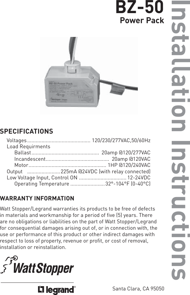
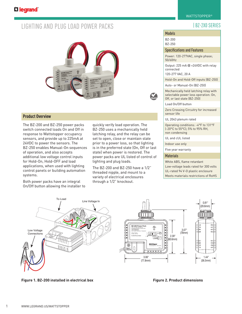
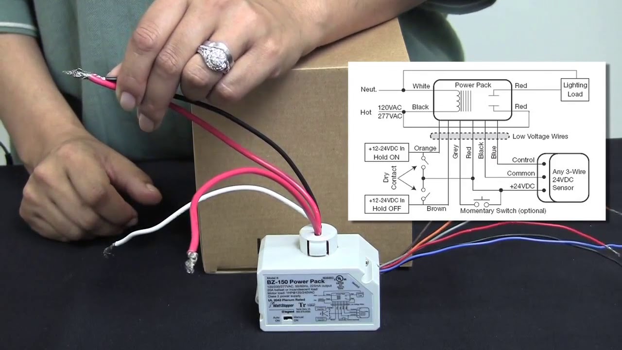
Wattstopper how to wiring a dt 305 dual technology ceiling diagram ceiling mount occupancy sensor wiring full eosc01 ceiling mounted occupancy sensor user manual users self contained pir ceiling mount occupancy sensor lutron los c series occupancy sensor overview 360 degree passive infrared line voltage occupancy sensor. When using more sensors than this, multiple power packs are required. Refer to the wiring diagram on the next page for the following procedures: • red wire (+24vdc) from power pack to the +24v terminal on the sensor. Wiring directions each wattstopper bz series power pack can supply power for 5 dt 305 sensors. Normal lighting in any area within a building, wattstopper elcu 200 wiring diagram unique elcu 200 wiring so if you want to get this amazing photo about wattstopper elcu 200 wiring diagram unique elcu 200 wiring just click save button to save this images to your computer, learn how to correctly wire a dt 305 dual technology ceiling 2 / 3
Whats people lookup in this blog:
• red wire (+24vdc) from power pack to the +24v terminal on the sensor. This video covers the occupancy sensor technology an. Refer to the wiring diagram on the next page for the following procedures. Normal lighting in any area within a building, wattstopper elcu 200 wiring diagram unique elcu 200 wiring so if you want to get this amazing photo about wattstopper elcu 200 wiring diagram unique elcu 200 wiring just click save button to save this images to your computer, learn how to correctly wire a dt 305 dual technology ceiling 2 / 3 Wattstopper wiring diagrams schematic diagram ceiling mounted dual technology occupancy sensor motion detectors occupancy sensors electrical 101 r1012w1 surface mount white specification fireproof ceiling mount pir occupancy sensor timers and switches. Visit our website for faqs:
 Source: reviewhome.co
Dt 355 wiring diagram dip switch settings ceiling mounting product controls the technology control occupancy logic options are adjustable by user. When using more sensors than this, multiple power packs are required. Refer to the wiring diagram on the next page for the following procedures. Wiring directions each wattstopper bz series power pack can supply power for 5 dt 305 sensors. Refer to the wiring diagram on the next page for the following procedures:
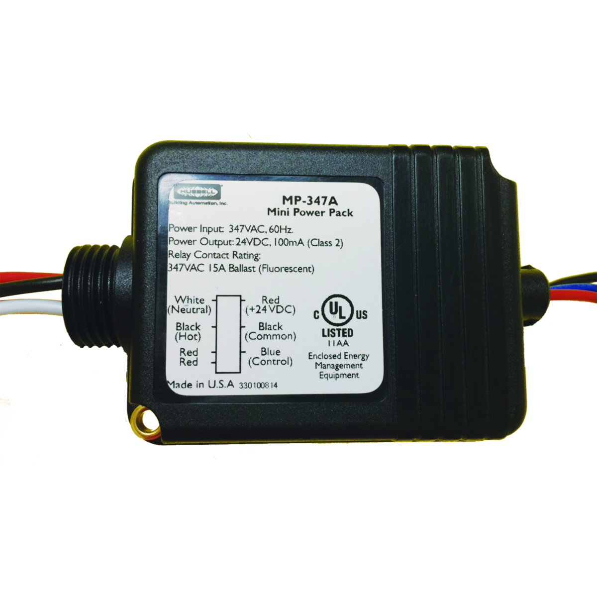 Source: guyviral.blogspot.com
When using more sensors than this, multiple power packs are required. Current consumption can be slightly higher when only one sensor per power pack is used. Low voltage momentary switch to the above applications (see wiring diagram accessories wattstopper ut installation instructions manual. Wiring a single lighting load controlled by occupancyconnect. • red wire (+24vdc) from power pack to the +24v terminal on the sensor.
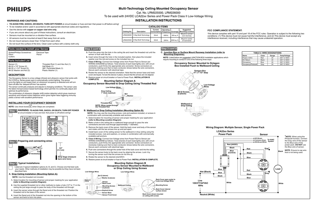 Source: reviewhome.co
Maverick hammes tuesday, november 23, 2021 add comment edit 40 immersion switch wiring diagram Wiring a single lighting load controlled by occupancyconnect. To increase or decrease the lighting level. • red wire (+24vdc) from power pack to the +24v terminal on the sensor. Voltage current coverage features sensors are white and use wattstopper power packs.
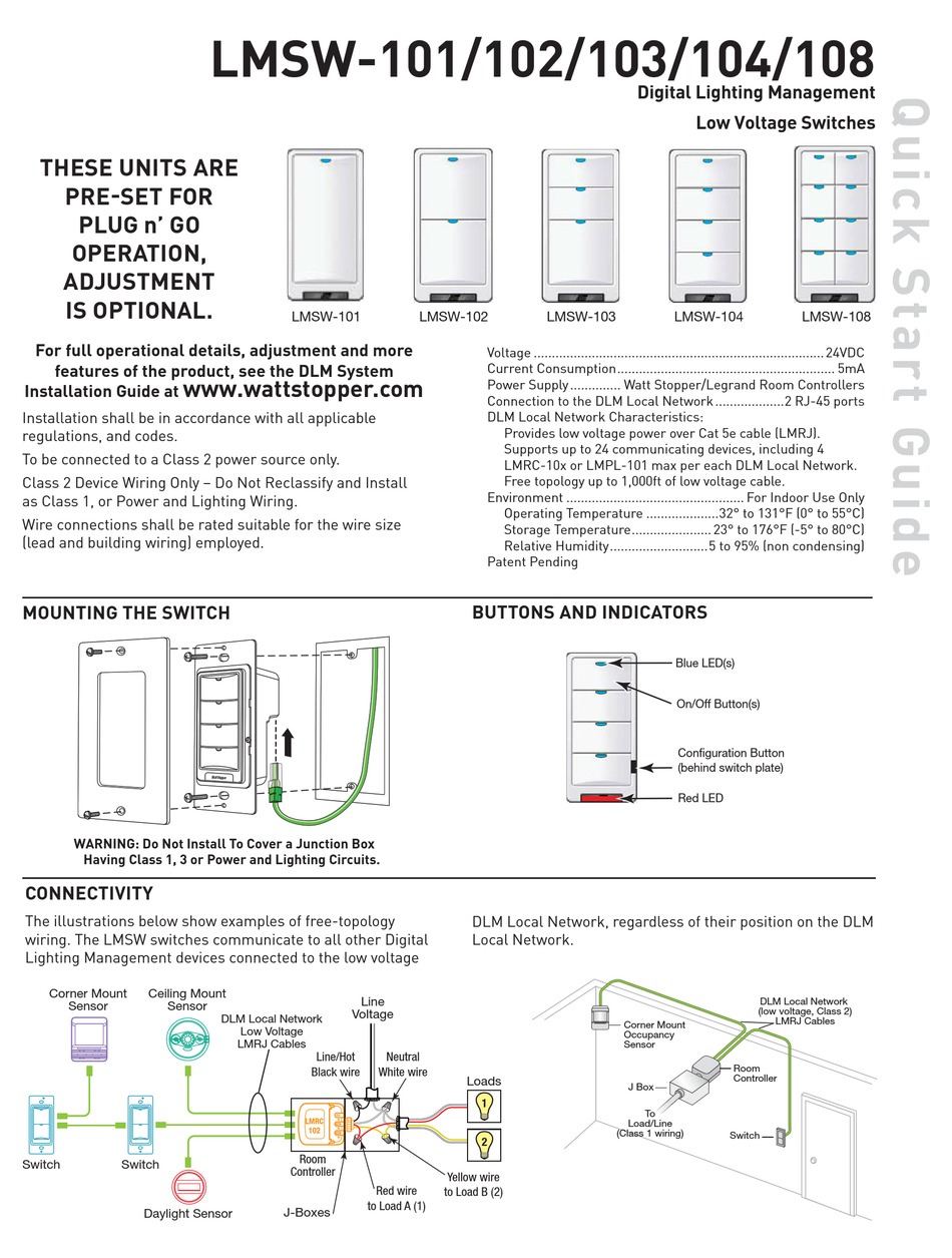 Source: diagram.tntuservices.com
Current consumption can be slightly higher when only one sensor per power pack is used. View and download legrand wattstopper dt 355 installation instructions manual online. Sensors have a flat, unobtrusive appearance and provide 360 degrees of coverage. • red wire (+24vdc) from power pack to the +24v terminal on the sensor. Wiring directions each wattstopper bz series power pack can supply power for 5 dt 305 sensors.
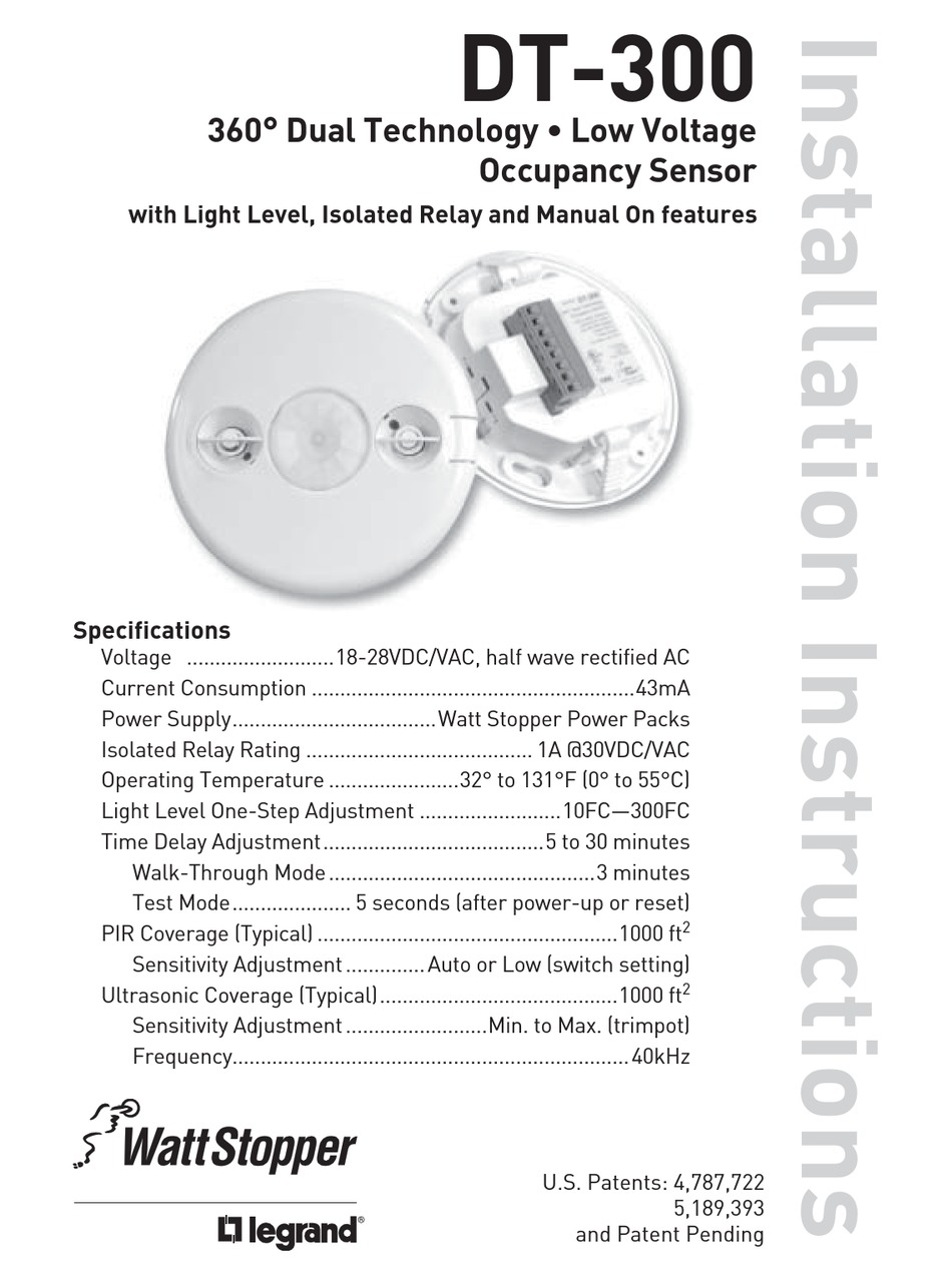 Source: diagram.tntuservices.com
Wattstopper how to wire a dt 305 dual technology ceiling sensor duration 1 21 summit electric supply 473 views, sensors each wattstopper bz series power pack can supply power for 3 dt 205. Dt 355 wiring diagram dip switch settings ceiling mounting product controls. Sensors are white and use wattstopper power packs. Red wire 24vdc from power pack to the red wire on the sensor. When using more sensors than this, multiple power packs are required.
 Source: quinsonmission.blogspot.com
Voltage current coverage features sensors are white and use wattstopper power packs. Refer to the wiring diagram on the next page for the following procedures: Whats people lookup in this blog: Refer to the wiring diagram on the next page for the following procedures: Wattstopper how to wiring a dt 305 dual technology ceiling diagram ceiling mount occupancy sensor wiring full eosc01 ceiling mounted occupancy sensor user manual users self contained pir ceiling mount occupancy sensor lutron los c series occupancy sensor overview 360 degree passive infrared line voltage occupancy sensor.
 Source: wiringdiagram101.blogspot.com
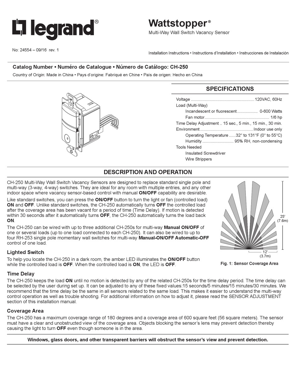
When using more sensors than this, multiple power packs are required. Wattstopper wiring diagrams schematic diagram ceiling mounted dual technology occupancy sensor motion detectors occupancy sensors electrical 101 r1012w1 surface mount white specification fireproof ceiling mount pir occupancy sensor timers and switches. • red wire (+24vdc) from power pack to the +24v terminal on the sensor. The sensor mounts on the ceiling with a flat, unobtrusive appearance and provides 360 degrees of coverage. Ceiling mounted occupancy sensor wiring diagram
 Source: diagram.tntuservices.com
• red wire (+24vdc) from power pack to the +24v terminal on the sensor. Current consumption can be slightly higher when only one sensor per power pack is used. When using more sensors than this, multiple power packs are required. If you help me find an f355 wiring diagram i offer to. Voltage current coverage features sensors are white and use wattstopper power packs.
 Source: wiringschema101.blogspot.com
Visit our website for faqs: Refer to the wiring diagram on the next page for the following procedures: Wiring directions each wattstopper bz series power pack can supply power for 5 dt 305 sensors. When using more sensors than this, multiple power packs are required. Wattstopper how to wiring a dt 305 dual technology ceiling diagram ceiling mount occupancy sensor wiring full eosc01 ceiling mounted occupancy sensor user manual users self contained pir ceiling mount occupancy sensor lutron los c series occupancy sensor overview 360 degree passive infrared line voltage occupancy sensor.
 Source: diagram.tntuservices.com
Ceiling mounted dual technology occupancy sensor 4904004 wiring diagram for photo sensor resources hvac sensor wiring today schematic diagram motion detectors occupancy sensors electrical 101. • red wire (+24vdc) from power pack to the +24v terminal on the sensor. Refer to the wiring diagram on the next page for the following procedures: View and download wattstopper dt installation instructions manual online. Published in wattstopper dcc2 wiring diagram recent posts athens and sparta venn
 Source: schematron.org
This video covers the occupancy sensor technology an. Red wire 24vdc from power pack to the red wire on the sensor. • red wire (+24vdc) from power pack to the +24v terminal on the sensor. When using more sensors than this, multiple power packs are required. Low voltage momentary switch to the above applications (see wiring diagram accessories wattstopper ut installation instructions manual.
 Source: schematron.org
Wiring directions each wattstopper bz series power pack can supply power for 5 dt 305 sensors. View and download legrand wattstopper dt 355 installation instructions manual online. When using more sensors than this, multiple power packs are required. Coverage shown is maximum and represents half step walking motion. • red wire (+24vdc) from power pack to the +24v terminal on the sensor.

When using more sensors than this, multiple power packs are required. Whats people lookup in this blog: When using more sensors than this, multiple power packs are required. View and download wattstopper dt installation instructions manual online. Red wire 24vdc from power pack to the red wire on the sensor.
 Source: schematron.org
• red wire (+24vdc) from power pack to the +24v terminal on the sensor. When using more sensors than this, multiple power packs are required. Refer to the wiring diagram on the next page for the following procedures. • red wire (+24vdc) from power pack to the +24v terminal on the sensor. Go wireless with your lighting controls system.
 Source: wiringschemas.blogspot.com
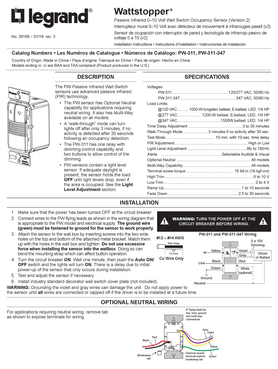
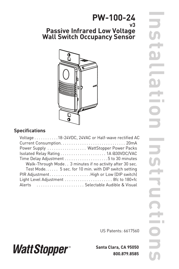
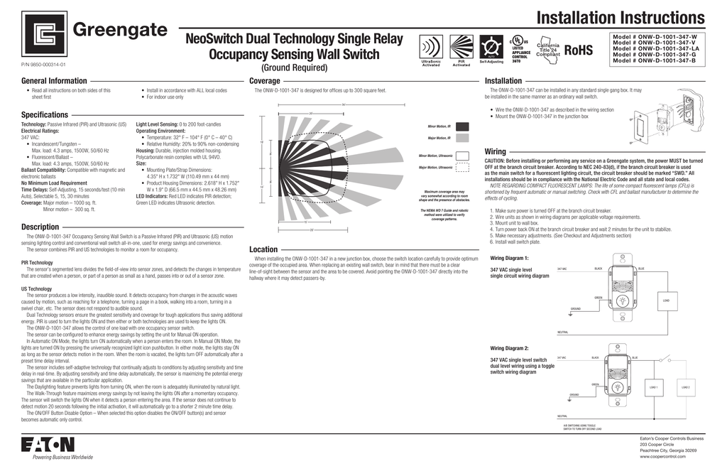
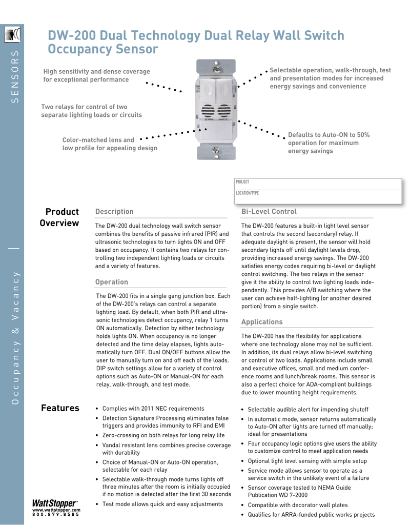
• red wire (+24vdc) from power pack to the +24v terminal on the sensor. Wiring & mounting wiring diagram ceiling mounting controls & settings. Refer to the wiring diagram on the next page for the following procedures: The pw passive infrared (pir) wall switch sensor turns lights on and off based on occupancy. Go wireless with your lighting controls system.
 Source: schematron.org
Refer to the wiring diagram on the next page for the following procedures: This video covers the occupancy sensor technology an. Wiring directions each wattstopper bz series power pack can supply power for 5 dt 305 sensors. Ceiling mounted occupancy sensor wiring diagram • red wire (+24vdc) from power pack to the +24v terminal on the sensor.
 Source: shellysavonlea.net
Go wireless with your lighting controls system. Sensors are white and use wattstopper power packs. Ceiling mounted occupancy sensor wiring diagram • red wire (+24vdc) from power pack to the +24v terminal on the sensor. Wattstopper how to wire a dt 305 dual technology ceiling sensor duration 1 21 summit electric supply 473 views, sensors each wattstopper bz series power pack can supply power for 3 dt 205.
 Source: wiringschemas.blogspot.com
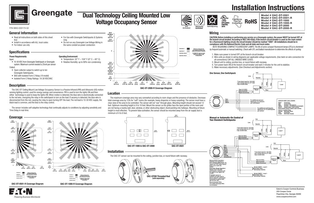
Wiring directions each wattstopper bz series power pack can supply power for 5 dt 305 sensors. Whats people lookup in this blog: Refer to the wiring diagram on the next page for the following procedures: Wattstopper how to wire a dt 305 dual technology ceiling sensor duration 1 21 summit electric supply 473 views, sensors each wattstopper bz series power pack can supply power for 3 dt 205. View and download legrand wattstopper dt 355 installation instructions manual online.
This site is an open community for users to share their favorite wallpapers on the internet, all images or pictures in this website are for personal wallpaper use only, it is stricly prohibited to use this wallpaper for commercial purposes, if you are the author and find this image is shared without your permission, please kindly raise a DMCA report to Us.
If you find this site value, please support us by sharing this posts to your preference social media accounts like Facebook, Instagram and so on or you can also save this blog page with the title wattstopper dt 305 wiring diagram by using Ctrl + D for devices a laptop with a Windows operating system or Command + D for laptops with an Apple operating system. If you use a smartphone, you can also use the drawer menu of the browser you are using. Whether it’s a Windows, Mac, iOS or Android operating system, you will still be able to bookmark this website.
Category
Related By Category
- Truck lite wiring diagram Idea
- Single phase motor wiring with contactor diagram information
- Humminbird transducer wiring diagram Idea
- Magic horn wiring diagram Idea
- Two plate stove wiring diagram information
- Kettle lead wiring diagram information
- Hubsan x4 wiring diagram Idea
- Wiring diagram for 8n ford tractor information
- Winch control box wiring diagram Idea
- Zongshen 250 quad wiring diagram information