Water pump wiring diagram single phase Idea
Home » Trend » Water pump wiring diagram single phase Idea
Your Water pump wiring diagram single phase images are available. Water pump wiring diagram single phase are a topic that is being searched for and liked by netizens now. You can Get the Water pump wiring diagram single phase files here. Download all free images.
If you’re searching for water pump wiring diagram single phase images information connected with to the water pump wiring diagram single phase interest, you have pay a visit to the right blog. Our website frequently gives you suggestions for downloading the maximum quality video and picture content, please kindly hunt and locate more enlightening video content and images that fit your interests.
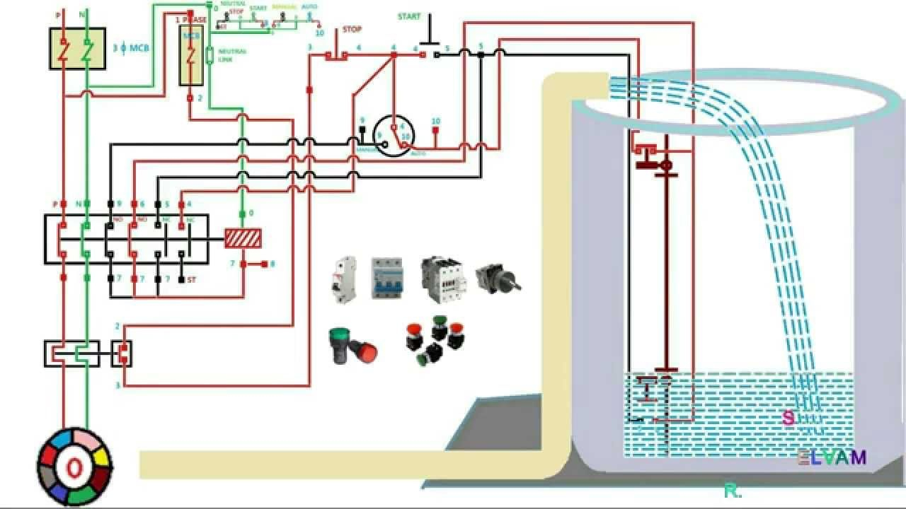
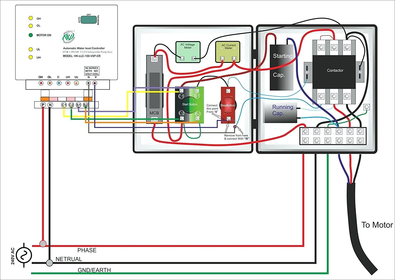
Water Pump Wiring Diagram Single Phase. Single phase wiring diagram for hp pumps with governor switch: Wiring diagram of water drainage tank note: Single phase submersible pump control box wiring diagram 3 wire submersible pump wiring diagram in submersible pump control box we use a capacitor a resit able thermal overload and dpst switch double pole single throw. Start winding resistance is probably greater than run winding resistance.
 Single Phase Jet Pump Controller Circuit From homemade-circuits.com
Water pump wiring diagram single phase literature library xylem applied water systems united. Dedicated circuit for well pumps. Single phase wiring diagram for hp pumps with governor switch: Single phase submersible pump control box wiring diagram 3 wire submersible pump wiring diagram in submersible pump control box we use a capacitor a resit able thermal overload and dpst switch double pole single throw. The motor stops pumping while the water in the water drainage tank goes Single phase wiring diagram with governor switch:
Diy wiring a consumer unit and installation distribution.
Kig inc new and used air cooled chillers from carrier. Plumbing courses pcd collegesa plumbing trade school. Please make sure switch �water filling /water drainage� to �water drainage �. Submersible pump control box wiring diagram for 3 wire single phase submersible pump submersible electrical circuit diagram. Submersible pumps are usually installed in wells which are at least 90. However, it does not imply link between the cables.
Source: electricaltutorials.org
Water pump wiring troubleshooting repair diagrams how to install and wire a well installation guide run submersible using relays what relay configuration can be quora electrician single phase starter facebook aim manual page 54 motors controls motor maintenance north america franklin electric schematic diagram of pv pumping system scientific circuit control. Water pump wiring diagram single phase literature library xylem applied water systems united. Dedicated circuit for well pumps. Two (2) are hot leads. 3 phase electrical wiring diagram 3 phase electrical.
 Source: wiring09.blogspot.com
Single phase wiring diagram for hp pumps with governor switch: Suction screen or pull pump and clean. 2 wire well pump wiring diagram. Start winding resistance is probably greater than run winding resistance. The motor stops pumping while the water in the water drainage tank goes
 Source: ricardolevinsmorales.com
Connections loose see wiring diagram or misconnected in in control box. 220v single phase motor wiring diagram 220v single phase. Submersible pump control box wiring diagram for 3 wire single phase submersible pump submersible well pump submersible wiring diagram for 220 volt submersible pump submersible pump 1993 ford mustang wiring diagram 2001 ford mus submersible pump submersible well pump sump pump In the video i shown a single phase submersible pump starter diagram in which shown the dpst switch thermal overload protector motor capacitor and the complete wiring connection with submersible. Submersible motor control box wiring | single phase water pump | water pumppump location.your submersible pump should be installed no less than 5 feet.
 Source: electricaltutorials.org
The last one (1) connects the capacitor motor. Suction screen or pull pump and clean. Submersible motor control box wiring | single phase water pump | water pumppump location.your submersible pump should be installed no less than 5 feet. Connection diagram of single phase submersible motor. Pump not submerged check water level in well.
 Source: franklinwater.com
Find which wire pairs belong together. The wiring connection of submersible pump control box is very simple. The last one (1) connects the capacitor motor. Single action, vertical and wide angle. Kig inc new and used air cooled chillers from carrier.
 Source: electronics.stackexchange.com
Pump not submerged check water level in well. Single action control switches can only be connected through a control panel. Connection diagram of single phase submersible motor. Single phase submersible pump starter wiring diagram download single. Diy wiring a consumer unit and installation distribution.
 Source: annawiringdiagram.com
Water pump wiring diagram single phase diy wiring a three phase consumer unit distribution board. Two (2) are hot leads. Kb pump 230v wiring, single phase water pump control panel wiring diagram fresh 3 wire submersible tech topics simplify water well pump control circuits setup rh nationaldriller 3 phase generator wiring heater control wiring However, it does not imply link between the cables. Please make sure switch �water filling /water drainage� to �water drainage �.
 Source: ipalmoil.com
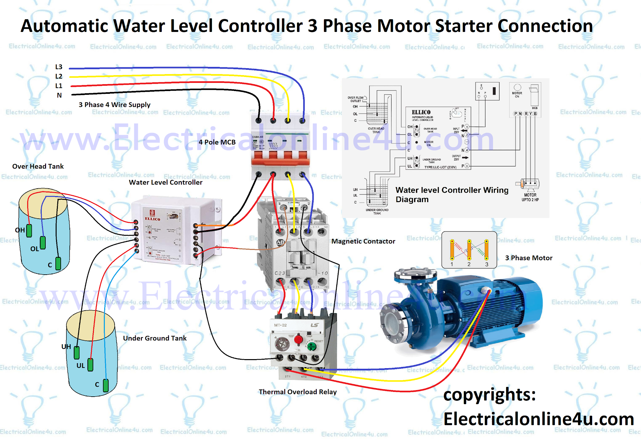
Automatic water level controller wiring diagram for 3 phase motor submersible pump water pump motor submersible pump electrical installation. 15 franklin electric 1 2 hp motor wiring diagram. The wiring connection of submersible pump control box is very simple. Single action, vertical and wide angle. Suction screen or pull pump and clean.
 Source: perantausepilodge.blogspot.com
The last one (1) connects the capacitor motor. Single phase submersible pump starter wiring diagram now if you did not know about the star, run and common wire in your pump motor then follow the below compressor terminals identifying tutorial and same follow. Water pump wiring diagram single phase literature library xylem applied water systems united. Owner’s manual ds2 series 60 cycle self priming. 3 motor 10 gpm deep potable efsub5 123hd the lovetoknow 6 lessons for doing it right 4 efsub7 122hd aim manual page 54 single phase motors controls maintenance north america franklin electric rs485 hydrostatic cesspool sea transducer 316l level sensor.
 Source: schematicandwiringdiagram.blogspot.com
According to earlier, the lines in a single phase motor wiring diagram with capacitor represents wires. Incorrect voltage see d page 20. The main points that we will cover in this video are as. Single phase submersible pump control box wiring diagram 3 wire submersible pump wiring diagram in submersible pump control box we use a capacitor a resit able thermal overload and dpst switch double pole single throw. Submersible motor control box wiring | single phase water pump | water pumppump location.your submersible pump should be installed no less than 5 feet.
 Source: tinyjudson.blogspot.com
Water pump wiring troubleshooting repair diagrams aim manual page 54 single phase motors and controls motor maintenance north america franklin electric electrician. According to earlier, the lines in a single phase motor wiring diagram with capacitor represents wires. Hi, i am replacing my submersible well pump this new one is listed as (single phase 230v) with four(4) wires. The main points that we will cover in this video are as. 3 phase electrical wiring diagram 3 phase electrical.
 Source: wiringideas.blogspot.com
Pump not submerged check water level in well. Wiring diagram for water well pump wiring diagram line wiring diagram. April 18 2021 by masuzi. Occasionally, the wires will cross. Please make sure switch �water filling /water drainage� to �water drainage �.
 Source: wiringschemas.blogspot.com
Single action, vertical and wide angle. Submersible pump control box wiring diagram for 3 wire single phase submersible pump submersible electrical circuit diagram. Single phase submersible pump starter wiring diagram download single. Start winding resistance is probably greater than run winding resistance. Occasionally, the wires will cross.
 Source: electricalonline4u.com
Float switch wiring diagram for water pump/ how to. Single phase wiring diagram with governor switch: Wiring diagram for a stove plug askmediy. Plumbing courses pcd collegesa plumbing trade school. Suction screen or pull pump and clean.
 Source: wiringschemas.blogspot.com
Single phase submersible pump control box wiring diagram 3 wire submersible pump wiring diagram in submersible pump control box we use a capacitor a resit able thermal overload and dpst switch double pole single throw. The complete guide of single phase motor wiring with circuit breaker and contactor diagram electrical circuit diagram circuit diagram electrical wiring diagram. In the video i shown a single phase submersible pump starter diagram in which shown the dpst switch thermal overload protector motor capacitor and the complete wiring connection with submersible. Two (2) are hot leads. Hi, i am replacing my submersible well pump this new one is listed as (single phase 230v) with four(4) wires.
 Source: homemade-circuits.com
Float switch wiring diagram for water pump | float switch wiring single phase. Water pump wiring diagram single phase literature library xylem applied water systems united. Injunction of two wires is usually. The pump is used to fill a tank with water. Single phase submersible pump control box wiring diagram 3 wire submersible pump wiring diagram in submersible pump control box we use a capacitor a resit able thermal overload and dpst switch double pole single throw.
 Source: annawiringdiagram.com
Diy wiring a consumer unit and installation distribution. Black wires go to black wires, and the green wire (the ground) goes to the ground wire. Diy wiring a consumer unit and installation distribution. Aim manual page 57 single phase motors and controls motor maintenance north america water franklin electric 3 4 hp control box for submersible well pump wire 230v motors 102 95 picclick submersible well pump wiring diagrams lovetoknow April 18 2021 by masuzi.
 Source: electroniclinic.com
Kb pump 230v wiring, single phase water pump control panel wiring diagram fresh 3 wire submersible tech topics simplify water well pump control circuits setup rh nationaldriller 3 phase generator wiring heater control wiring Plumbing courses pcd collegesa plumbing trade school. Now is where my confusion begins Submersible motor control box wiring | single phase water pump | water pumppump location.your submersible pump should be installed no less than 5 feet. Single phase submersible pump starter wiring diagram on water control panel inside to submersible pump electrical circuit diagram sump pump submersible pump control box wiring single phase earth bondhon submersible pump submersible pumps
This site is an open community for users to do submittion their favorite wallpapers on the internet, all images or pictures in this website are for personal wallpaper use only, it is stricly prohibited to use this wallpaper for commercial purposes, if you are the author and find this image is shared without your permission, please kindly raise a DMCA report to Us.
If you find this site beneficial, please support us by sharing this posts to your favorite social media accounts like Facebook, Instagram and so on or you can also bookmark this blog page with the title water pump wiring diagram single phase by using Ctrl + D for devices a laptop with a Windows operating system or Command + D for laptops with an Apple operating system. If you use a smartphone, you can also use the drawer menu of the browser you are using. Whether it’s a Windows, Mac, iOS or Android operating system, you will still be able to bookmark this website.
Category
Related By Category
- Predator 670 engine wiring diagram Idea
- Frsky x8r wiring diagram information
- Pioneer ts wx130da wiring diagram Idea
- Johnson 50 hp wiring diagram Idea
- Kohler voltage regulator wiring diagram Idea
- Johnson 50 hp outboard wiring diagram information
- Kti hydraulic remote wiring diagram Idea
- Pyle plpw12d wiring diagram information
- Tx9600ts wiring diagram information
- Lifan 50cc wiring diagram information