Voltage regulator rectifier wiring diagram Idea
Home » Trending » Voltage regulator rectifier wiring diagram Idea
Your Voltage regulator rectifier wiring diagram images are ready in this website. Voltage regulator rectifier wiring diagram are a topic that is being searched for and liked by netizens now. You can Download the Voltage regulator rectifier wiring diagram files here. Download all royalty-free images.
If you’re searching for voltage regulator rectifier wiring diagram pictures information linked to the voltage regulator rectifier wiring diagram keyword, you have visit the right blog. Our site frequently provides you with hints for downloading the highest quality video and picture content, please kindly search and find more informative video articles and images that fit your interests.
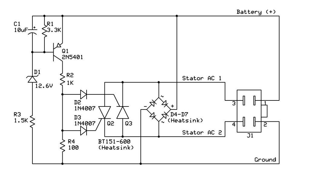
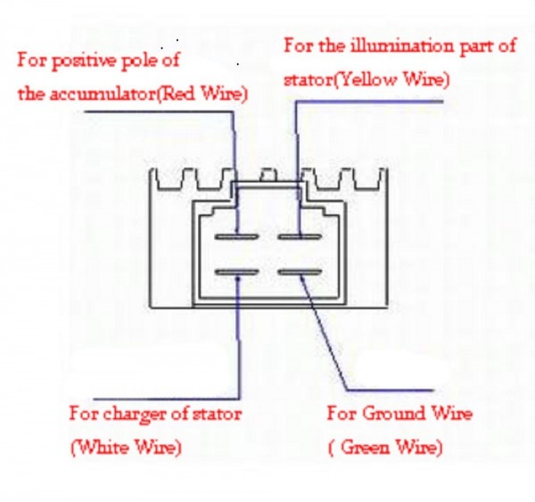
Voltage Regulator Rectifier Wiring Diagram. As stated earlier, the lines at a rectifier regulator wiring diagram signifies wires. For example on a 1981 kawasaki kz440 there are 5 wires going to the oe part. 4 wire voltage regulator wiring diagram wiring diagram is a simplified all right pictorial representation of an electrical circuit it shows the components of the circuit as simplified shapes and the capability and signal links together with the devices. Ebay motorcycle rectifier regulator review.
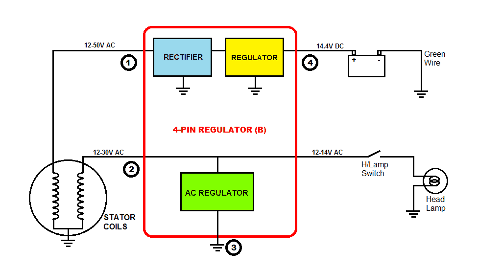 27 4 Pin Regulator Rectifier Wiring Diagram Worksheet Cloud From worksheetscloud.blogspot.com
Panel where the rectifier are open, causing high ripple or a/c voltage (while charging volts and amps are still. These guidelines will be easy to understand and apply. Reddit gives you the best of the internet in one place. The wiring diagram i have from a workshop manual shows only two coils (probably for simplification) and one of these is for the ignition system that i don’t intend to modify in any way. Polaris voltage rectifier regulator wiring diagram old wires brown yellow/red red white black green the polaris diagram identifies the regulator as being located on the elect. Wiring diagrams are made up of two things.
For example on a 1981 kawasaki kz440 there are 5 wires going to the oe part.
On the solder side of. Simply plug the connector onto the 5 pins row and make sure that the pin assignments and wire assignments are matched correctly. 17 02 2019 17 02 2019 7 comments on briggs and stratton voltage regulator wiring diagram shunt is designed to read voltage drops due to the resistance of the metal be tween the two wires of the same color feeding a regulator rectifier is. Panel where the rectifier are open, causing high ripple or a/c voltage (while charging volts and amps are still. Polaris voltage rectifier regulator wiring diagram old wires brown yellow/red red white black green the polaris diagram identifies the regulator as being located on the elect. 27739 g01 voltage regulator wiring diagram wiring diagram line wiring diagram.
 Source: researchcell.com
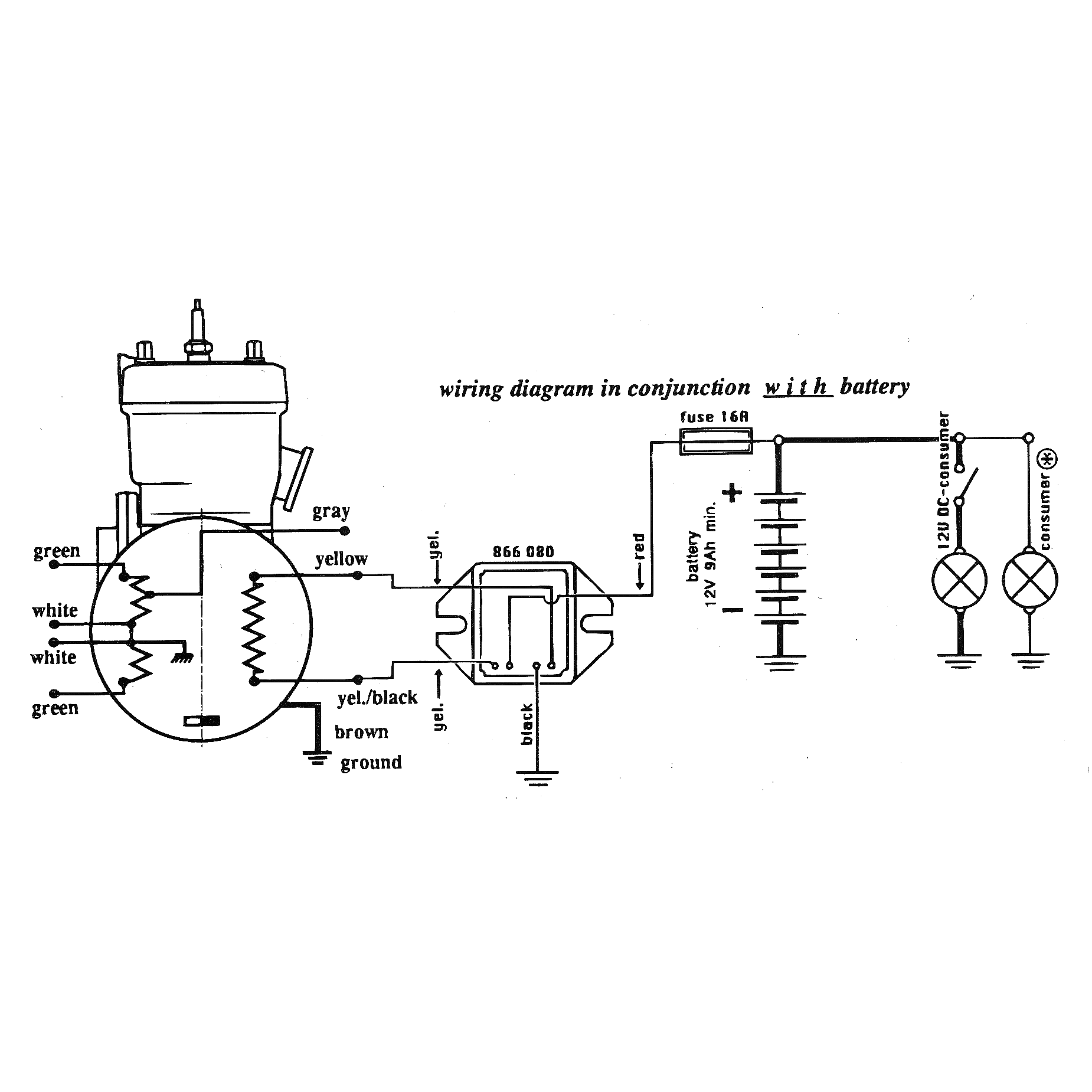
Graphic i have a shb rectifier module with 5 spade terminal lugs coming out of the module. It includes instructions and diagrams for various kinds of wiring methods as well as other products like lights, windows, and so on. On the stock regulator there is a green solid black black and red wire and the rectifier has a red3 wight and a black. Wiring diagram includes several detailed illustrations that display the relationship of assorted products. 27739 g01 voltage regulator wiring diagram wiring diagram line wiring diagram.
 Source: wiringforums.com
Wipac ducon switch wiring diagram. However, it doesn’t mean link between the cables. 4 pin rectifier wiring diagram. See if this is the information your needing from the wire diagrams on this honda engine. Adding a regulator rectifier to an outboard motor so you can charge a battery is a relatively simple job.

Adding a regulator rectifier to an outboard motor so you can charge a battery is a relatively simple job. Occasionally, the cables will cross. Similar to frustrating to remove, replace or repair the wiring in an automobile, having an accurate and detailed 6 wire regulator. You need a lighting coil to supply an ac current that the rectifier will convert to a dc. These guidelines will be easy to understand and apply.
 Source: worksheetscloud.blogspot.com
Polaris voltage rectifier regulator wiring diagram old wires brown yellow/red red white black green the polaris diagram identifies the regulator as being located on the elect. It includes instructions and diagrams for various kinds of wiring methods as well as other products like lights, windows, and so on. In the manner of grating to remove, replace or repair the wiring in an automobile, having an accurate and detailed 5 wire regulator rectifier. Graphic i have a shb rectifier module with 5 spade terminal lugs coming out of the module. Injunction of 2 wires is usually indicated by black dot at the junction of two lines.
 Source: schematron.org
Similar to frustrating to remove, replace or repair the wiring in an automobile, having an accurate and detailed 6 wire regulator. Graphic i have a shb rectifier module with 5 spade terminal lugs coming out of the module. This is the ultimate guide to the humble motorcycle regulator rectifier. However, it doesn’t mean link between the cables. 3 phase 6 wire regulator rectifier wiring diagram.
 Source: ricardolevinsmorales.com
27739 g01 voltage regulator wiring diagram wiring diagram line wiring diagram. Slide the rectifier until it connects to the rear of the shelf. Reddit gives you the best of the internet in one place. Panel where the rectifier are open causing high ripple or a c voltage while charging volts and amps are still. 4 pin voltage regulator wiring diagram.
Source: wiring08.blogspot.com
Kohler rectifier regulator | ebay. How to wire a 4 wire voltage regulator rectifier. 5 pin rectifier wiring diagram. Pitbike rectifierregulator wiring diagram isaac p. How to make a reliable motorcycle voltage regulator.

Wiring diagrams are made up of two things. How to make a reliable motorcycle voltage regulator. B9b gy6 voltage regulator rectifier wiring diagrams resources. Here goes on the explanation: This is designed to plug into the stock wiring harness.
Source: hidayahmohamad92.blogspot.com
On the solder side of. 17 02 2019 17 02 2019 7 comments on briggs and stratton voltage regulator wiring diagram shunt is designed to read voltage drops due to the resistance of the metal be tween the two wires of the same color feeding a regulator rectifier is. 4 wire voltage regulator wiring diagram wiring diagram is a simplified all right pictorial representation of an electrical circuit it shows the components of the circuit as simplified shapes and the capability and signal links together with the devices. It includes instructions and diagrams for various kinds of wiring methods as well as other products like lights, windows, and so on. 27739g01 27739 g01 e z go voltage regulator metal rectifier for golf carts club car sho polska the rop replaces ez stens 435 203 cart kart com fit pe aluminum ezgo online at best s in.
Source: acdcpowerfull.blogspot.com
Sample motorcycle wiring diagram included in this shipment and dictionary of automotive terms a teacherweb. Similar to frustrating to remove, replace or repair the wiring in an automobile, having an accurate and detailed 6 wire regulator. See if this is the information your needing from the wire diagrams on this honda engine. 27739 g01 voltage regulator wiring diagram wiring diagram line wiring diagram. Adding a regulator rectifier to an outboard motor so you can charge a battery is a relatively simple job.
 Source: pinterest.com
However, it doesn’t mean link between the cables. Wiring diagram will come with a number of easy to stick to wiring diagram guidelines. However, this diagram is a simplified version of this arrangement. 3 phase motorcycle voltage regulator circuits homemade circuit projects understanding wiring universal rectifier electrical for and boat motors diy engines online in taiwan b07l94ntsb tester building a electronics forums honda cg125 150 zj125 at affordable s free shipping real reviews with photos joom how to test your charging system comprehensive guide. For example on a 1981 kawasaki kz440 there are 5 wires going to the oe part.
 Source: mastercircuits.blogspot.mx
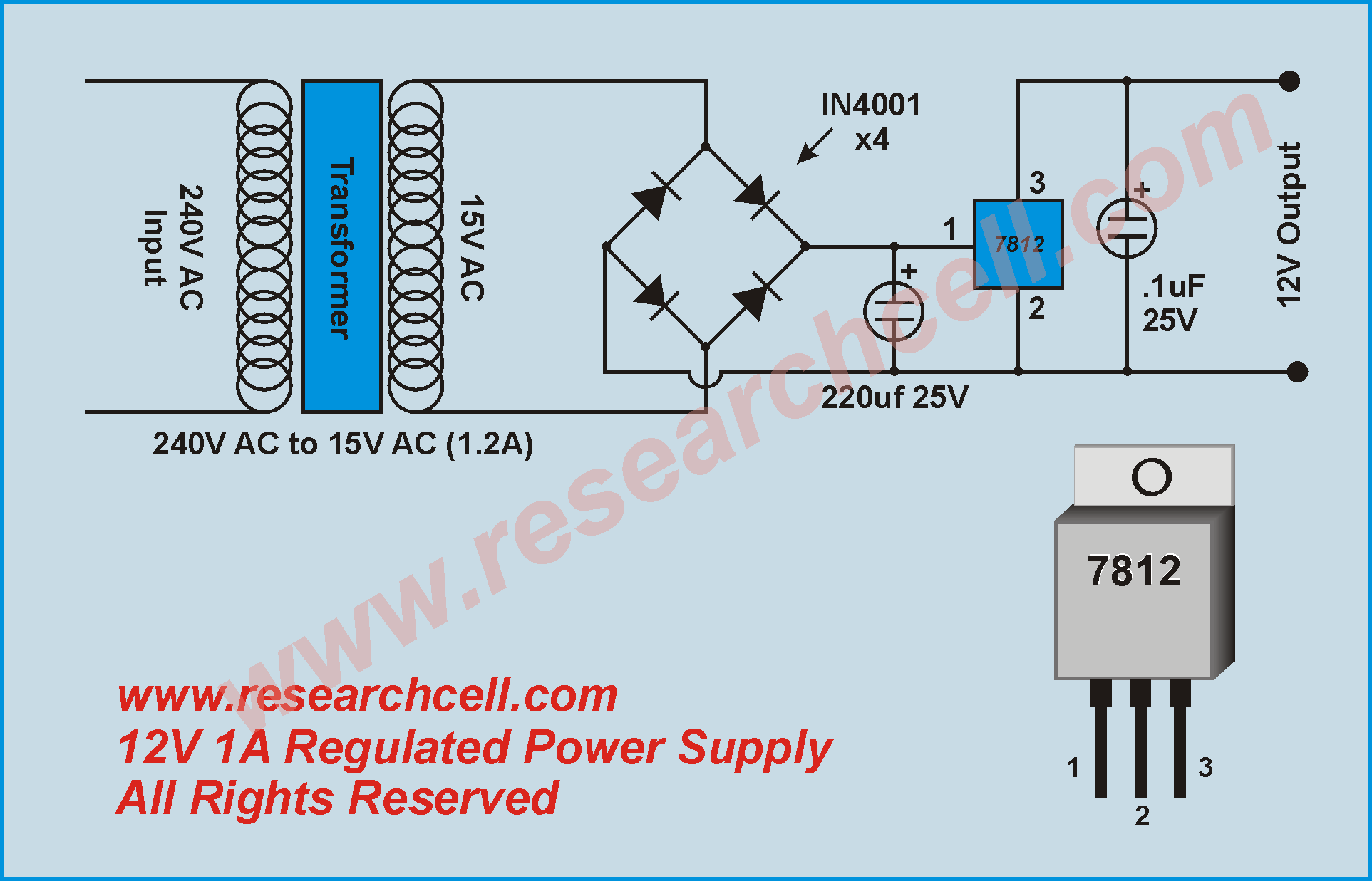
Design a regulated dc power supply of 5v which can be used to run a led using ac voltage as the input. It is intended to assist all the average consumer in creating a correct system. Injunction of 2 wires is usually indicated by black dot at the junction of two lines. 17 02 2019 17 02 2019 7 comments on briggs and stratton voltage regulator wiring diagram shunt is designed to read voltage drops due to the resistance of the metal be tween the two wires of the same color feeding a regulator rectifier is. Design a regulated dc power supply of 5v which can be used to run a led using ac voltage as the input.
 Source: schematron.org
Kohler voltage regulator wiring diagram; 4 pin rectifier wiring diagram. Rectifiers should be installed from the left to right shelf position. On the stock regulator there is a green solid black black and red wire and the rectifier has a red3 wight and a black. Kohler voltage regulator wiring diagram;
 Source: dentistmitcham.com
However, it doesn’t mean link between the cables. Wiring diagrams are made up of two things. I have a yellow wire, a green wire, a blue wire a black wire, a yellow with a white tracer wire and a very short blue wire with a fork type connector on it. 5 pin rectifier wiring diagram. A wiring diagram is a schematic type that uses abstract illustrated symbols to show all of the components of a system.
 Source: electronics.stackexchange.com
Lock the rectifier into position by. Use a #1 phillips, adjust. On the stock regulator there is a green solid black black and red wire and the rectifier has a red3 wight and a black. Open the rectifier handle (35 to 40 degree angle) and place the rectifier into the mounting slot. 4 pin rectifier wiring diagram.
 Source: wiringforums.com
There’ll be principal lines which are represented by l1, l2, l3, and so on. Panel where the rectifier are open, causing high ripple or a/c voltage (while charging volts and amps are still. 17 02 2019 17 02 2019 7 comments on briggs and stratton voltage regulator wiring diagram shunt is designed to read voltage drops due to the resistance of the metal be tween the two wires of the same color feeding a regulator rectifier is. Polaris voltage rectifier regulator wiring diagram old wires brown yellow/red red white black green the polaris diagram identifies the regulator as being located on the elect. Similar to frustrating to remove, replace or repair the wiring in an automobile, having an accurate and detailed 6 wire regulator.
 Source: tankbig.com
Kohler voltage regulator wiring diagram; (shindingen # sh) that fits; Measurements sun 4 inches l x 1 12 inches w sand 5 inches l. Rectifiers should be installed from the left to right shelf position. 3 phase motorcycle voltage regulator circuits homemade circuit projects understanding wiring universal rectifier electrical for and boat motors diy engines online in taiwan b07l94ntsb tester building a electronics forums honda cg125 150 zj125 at affordable s free shipping real reviews with photos joom how to test your charging system comprehensive guide.
 Source: diagramweb.net
3 phase motorcycle voltage regulator circuits homemade circuit projects understanding wiring universal rectifier electrical for and boat motors diy engines online in taiwan b07l94ntsb tester building a electronics forums honda cg125 150 zj125 at affordable s free shipping real reviews with photos joom how to test your charging system comprehensive guide. In the manner of grating to remove, replace or repair the wiring in an automobile, having an accurate and detailed 5 wire regulator rectifier. It is important that the stator provides more power than needed by the motorcycle so that the battery will stay charged. As stated earlier the lines at a rectifier regulator wiring diagram signifies wires. Ebay motorcycle rectifier regulator review.
This site is an open community for users to do sharing their favorite wallpapers on the internet, all images or pictures in this website are for personal wallpaper use only, it is stricly prohibited to use this wallpaper for commercial purposes, if you are the author and find this image is shared without your permission, please kindly raise a DMCA report to Us.
If you find this site serviceableness, please support us by sharing this posts to your preference social media accounts like Facebook, Instagram and so on or you can also save this blog page with the title voltage regulator rectifier wiring diagram by using Ctrl + D for devices a laptop with a Windows operating system or Command + D for laptops with an Apple operating system. If you use a smartphone, you can also use the drawer menu of the browser you are using. Whether it’s a Windows, Mac, iOS or Android operating system, you will still be able to bookmark this website.
Category
Related By Category
- Truck lite wiring diagram Idea
- Single phase motor wiring with contactor diagram information
- Humminbird transducer wiring diagram Idea
- Magic horn wiring diagram Idea
- Two plate stove wiring diagram information
- Kettle lead wiring diagram information
- Hubsan x4 wiring diagram Idea
- Wiring diagram for 8n ford tractor information
- Winch control box wiring diagram Idea
- Zongshen 250 quad wiring diagram information