Vfd wiring diagram Idea
Home » Trending » Vfd wiring diagram Idea
Your Vfd wiring diagram images are ready. Vfd wiring diagram are a topic that is being searched for and liked by netizens today. You can Download the Vfd wiring diagram files here. Get all royalty-free photos.
If you’re looking for vfd wiring diagram images information related to the vfd wiring diagram interest, you have pay a visit to the right site. Our website always provides you with suggestions for seeking the maximum quality video and picture content, please kindly surf and find more informative video articles and images that fit your interests.
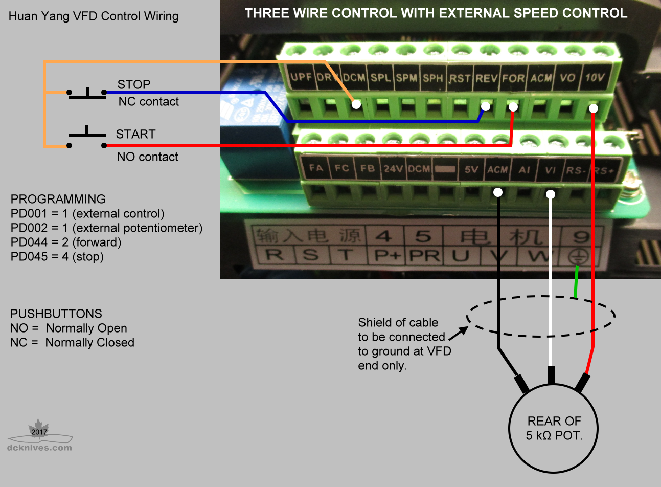
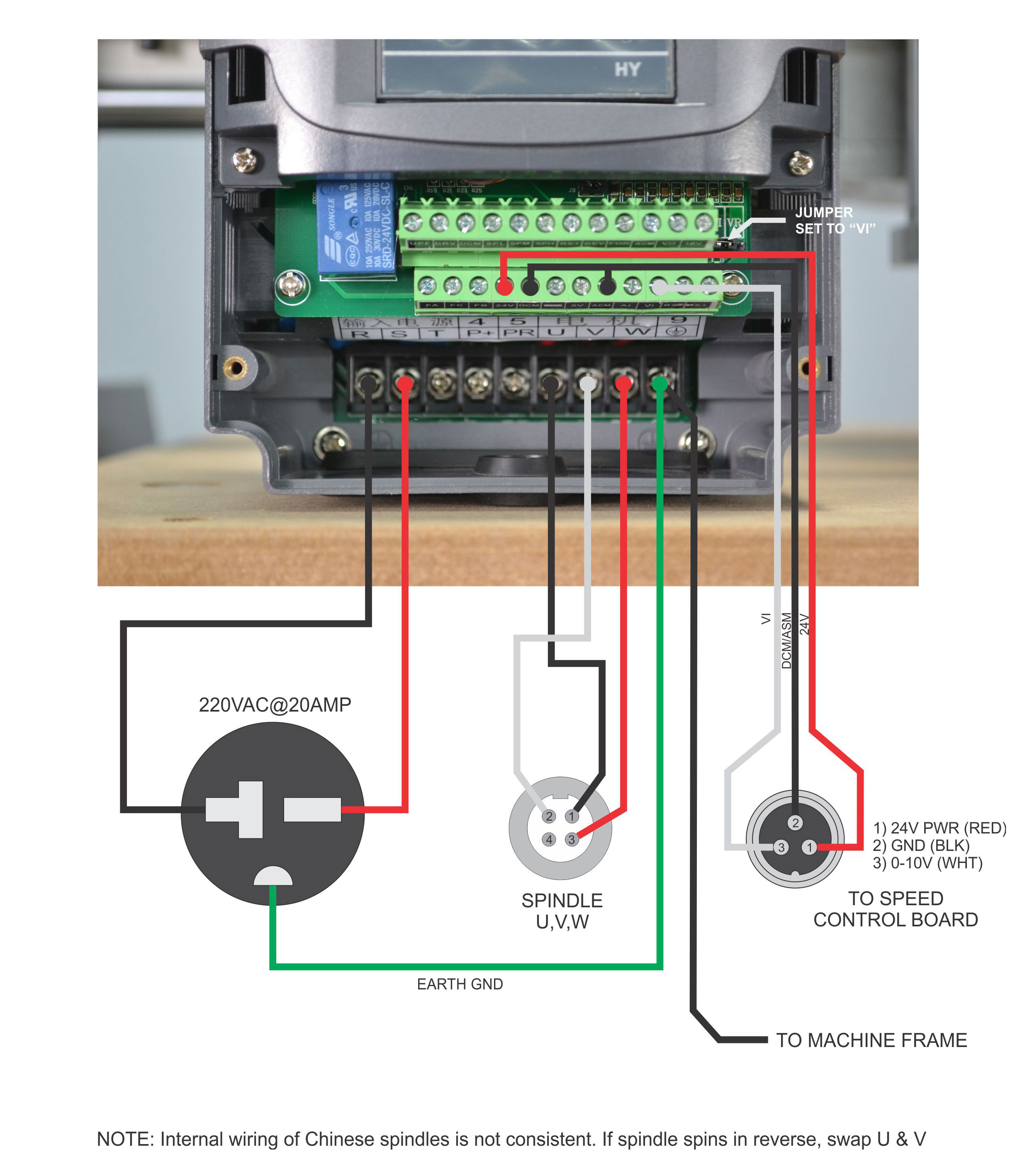
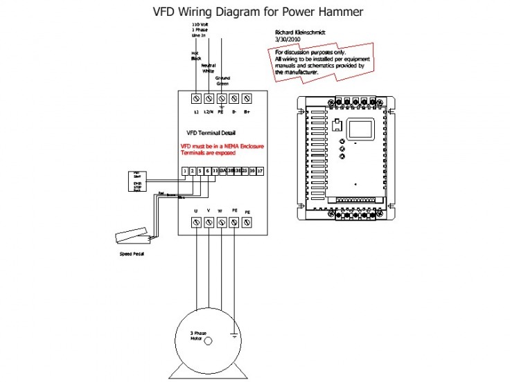
Vfd Wiring Diagram. Here is a picture gallery about siemens micromaster. Available in to 335 hp this modular and scalable standard drive may be configured in a wide variety of designs to meet many industrial drive applications. Nameplate description of hy series inverter Vfd control wiring diagram autocardesign.
 Beginner VFD Wiring From practicalmachinist.com
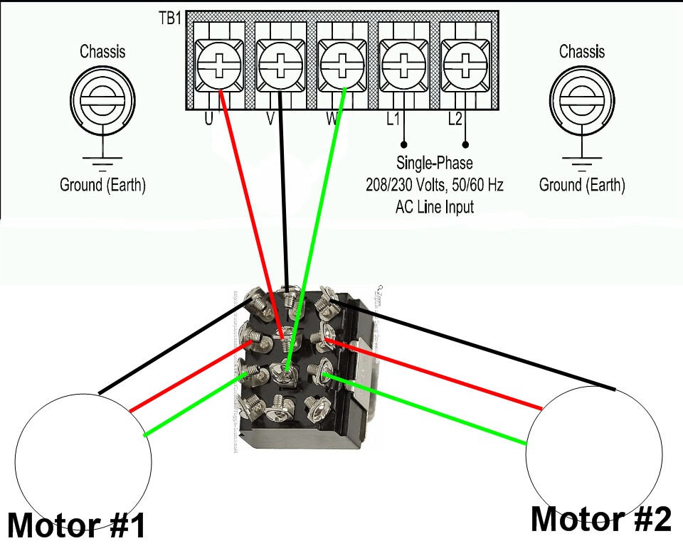
Vfd wiring diagram showing power in out and control device scientific file jpg probotix wiki start stop electrical4u allen bradley powerflex instrumentationtools. After applying the dc bus voltage across the igbts without the motor connected adjust the pwm 1k preset until the voltage across the rails become equal to the intended motor voltage specs. 8 16 2020 vfd control wiring diagram wiring diagram is a simplified all right pictorial representation of an electrical circuit it shows the components of the circuit as simplified shapes and the. Available in to 335 hp this modular and scalable standard drive may be configured in a wide variety of designs to meet many industrial drive applications. Application note ap0400076en vfd wiring best practices effective july 2014 2 eaton corporation www.eaton.com control wiring similar consideration need to be taken when looking at the control wiring. Nameplate description of hy series inverter
Here is a picture gallery about siemens micromaster.
Vfd start stop wiring diagram. Check if there is something wrong with the inner parts, wiring and circuit board. The vfds showed in the video are the d720s (230v single phase) and the d720 (230v three phase). Controlled environment that is suitable for the selected enclosure. Allen bradley powerflex 525 ac drives ppt online. Connect or do wiring as per vfd side drawing, you take +24 v from the vfd pcb directly.
 Source: wholefoodsonabudget.com
Vfd and their power and signal cabling section of this control panel wiring diagram. Allen bradley powerflex 525 ac drives ppt online. K1 no1, pb3, pb4, pb5 should be of potential free contact. Wiring diagrams for 3dtek vfd spindle and aio card. The rest of page 8 of this plc wiring diagram is related to some interlocks or conditions and also the power to the fan of the electric motor.
 Source: practicalmachinist.com
When you press the on push k1 contactor will hold and k1 no1 become nc. Check if each terminal is tightly locked and if there is any foreign article inside the inverter. Application note ap0400076en vfd wiring best practices effective july 2014 2 eaton corporation www.eaton.com control wiring similar consideration need to be taken when looking at the control wiring. Vfd and their power and signal cabling section of this control panel wiring diagram. The common elements inside a wiring diagram are ground, power, wire and connection, output devices, switches, resistors, logic gate, lights, etc.
 Source: 6.4wd.tech-aid.nl
The vfds showed in the video are the d720s (230v single phase) and the d720 (230v three phase). Vfd wiring diagram showing power in out and control device scientific file jpg probotix wiki start stop electrical4u allen bradley powerflex instrumentationtools. 1 the vfd s three phase ac input terminals r l1 s l2 t l3 the power line s input terminals connect to 3 phase ac power through line protection or leakage protection breaker it does not need to consider the connection of phase sequence. Vfd start stop wiring diagram. Learn the basic wiring of variable frequency drives vfd with our electrician steve quist.
 Source: 2020cadillac.com
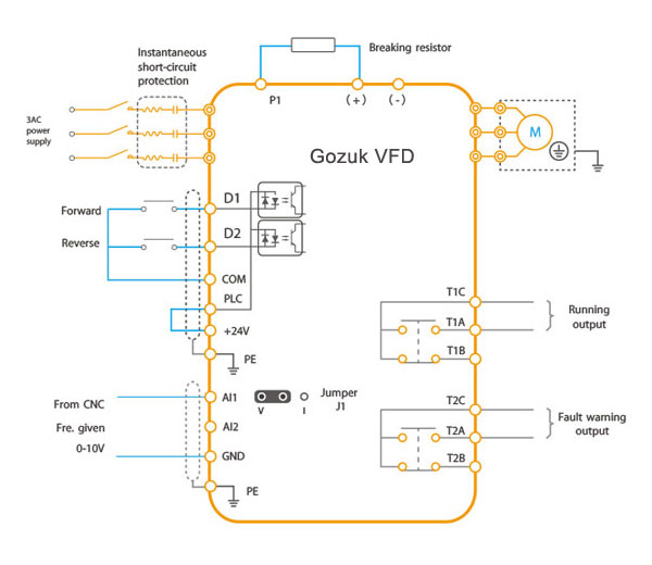
Wiring diagrams for 3dtek vfd spindle and aio card. Use the following chart to interpret the type code found on the and control wiring. Three phase vfd control motor forward and reverse. A variable frequency drive regulates the speed and operation of an electric motors. 1 the vfd s three phase ac input terminals r l1 s l2 t l3 the power line s input terminals connect to 3 phase ac power through line protection or leakage protection breaker it does not need to consider the connection of phase sequence.
 Source: cintakupadamuu.blogspot.com
K1 no1, pb3, pb4, pb5 should be of potential free contact. Vfd wiring diagram showing power in out and control device scientific file jpg probotix wiki start stop electrical4u allen bradley powerflex instrumentationtools. Vfd start stop wiring diagram. Ts1, enclosure fan1 standard on all nema 3r panels. A variable frequency drive regulates the speed and operation of an electric motors.
 Source: wiring.hpricorpcom.com
This is beneficial for both the individuals and for professionals who’re looking to find out more on how to set up a operating surroundings. Vfd wiring diagram showing power in out and control device scientific file jpg probotix wiki start stop electrical4u allen bradley powerflex instrumentationtools variable frequency drive for constant pressure water supply controlling vfds with manual inputs technical articles unitronics quick guide help desk software by vision helpdesk 3 phase induction motor. A variable frequency drive regulates the speed and operation of an electric motors. Wiring diagrams for 3dtek vfd spindle and aio card. (1) the vfd�s three phase ac input terminals (r/l1, s/l2, t/l3) the power line�s input terminals connect to 3 phase ac power through line protection or leakage protection breaker, it does not need to consider the connection of phase sequence.
 Source: youtube.com
Learn the basic wiring of variable frequency drives vfd with our electrician steve quist. Here is a picture gallery about siemens micromaster. Check if each terminal is tightly locked and if there is any foreign article inside the inverter. Controlled environment that is suitable for the selected enclosure. Vfd start stop wiring diagram electrical4u siemens plc pdf archives upmation controlling vfds with manual inputs technical articles how to control using ladder logic instrumentationtools design a variable frequency drive panel awc inc trainer for use in an agricultural electricity course mitsubishi installation and connection plc247 com.
 Source: thisoldmill.com
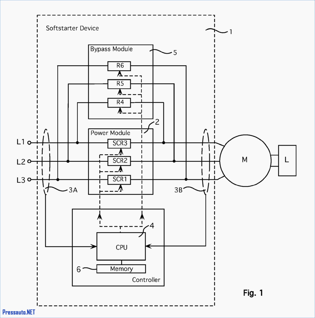
Check if each terminal is tightly locked and if there is any foreign article inside the inverter. The rest of page 8 of this plc wiring diagram is related to some interlocks or conditions and also the power to the fan of the electric motor. A wiring diagram is a kind of schematic which uses abstract pictorial symbols to demonstrate every one of the interconnections of components inside a system. Vfd wiring diagram showing power in out and control device scientific start stop electrical4u how to with plc using ladder logic instrumentationtools instructions add ons modifications sienci community forum controlling vfds manual inputs technical articles allen bradley powerflex understand better by the main circuit 3 phase induction motor. After applying the dc bus voltage across the igbts without the motor connected adjust the pwm 1k preset until the voltage across the rails become equal to the intended motor voltage specs.
 Source: probotix.com
Please read important notes at bottom before powering up the vfd!!!! Allen bradley powerflex vfd 700 to 750 753 drive 525 setup programming 40 ac drives parameter input and run off 110 for configuration low voltage rockwell automation modernization part iii 1305 adjule frequency 30 hp series not seeing digital inputs manual ppt 4m quick start blog ced solution. Wiring vfd motor control circuit diagram. Set dip switches as needed. The common elements inside a wiring diagram are ground, power, wire and connection, output devices, switches, resistors, logic gate, lights, etc.
 Source: sdmetalworks.weebly.com
Vfd wiring diagram showing power in out and control device scientific start stop electrical4u how to with plc using ladder logic instrumentationtools instructions add ons modifications sienci community forum controlling vfds manual inputs technical articles allen bradley powerflex understand better by the main circuit 3 phase induction motor. Allen bradley powerflex vfd 700 to 750 753 drive 525 setup programming 40 ac drives parameter input and run off 110 for configuration low voltage rockwell automation modernization part iii 1305 adjule frequency 30 hp series not seeing digital inputs manual ppt 4m quick start. When you press the on push k1 contactor will hold and k1 no1 become nc. Learn the basic wiring of variable frequency drives vfd with our electrician steve quist. Here is a picture gallery about siemens micromaster.
 Source: coveyandkelseycole.blogspot.com
A wiring diagram is a kind of schematic which uses abstract pictorial symbols to demonstrate every one of the interconnections of components inside a system. Nameplate description of hy series inverter Check if each terminal is tightly locked and if there is any foreign article inside the inverter. Ts1, enclosure fan1 standard on all nema 3r panels. Few days ago gohz made a 24v 2000w power inverter in home sharing some design schematics and circuit diagrams.
 Source: vfds.org
Wiring diagrams for 3dtek vfd spindle and aio card. It shows the elements of the circuit as simplified shapes, as well as the power as well as signal connections between the devices. Vfd wiring diagram showing power in out and control device scientific file jpg probotix wiki start stop electrical4u allen bradley powerflex instrumentationtools. When you press the on push k1 contactor will hold and k1 no1 become nc. This is beneficial for both the individuals and for professionals who’re looking to find out more on how to set up a operating surroundings.
 Source: 2020cadillac.com
Few days ago gohz made a 24v 2000w power inverter in home sharing some design schematics and circuit diagrams. The vfds showed in the video are the d720s 230v single phase and the d720 230v three phase. Internal circuit of variable frequency drive how to build a 3 phase vfd single the schematic or diagram svc can refer driver prototype set triac for ac induction motors general vsi working principle your electrical make metso brief explaination about three control motor forward basics diagrams with plc. Check if the operator buttons are all right. K1 no1, pb3, pb4, pb5 should be of potential free contact.
 Source: wiring09.blogspot.com
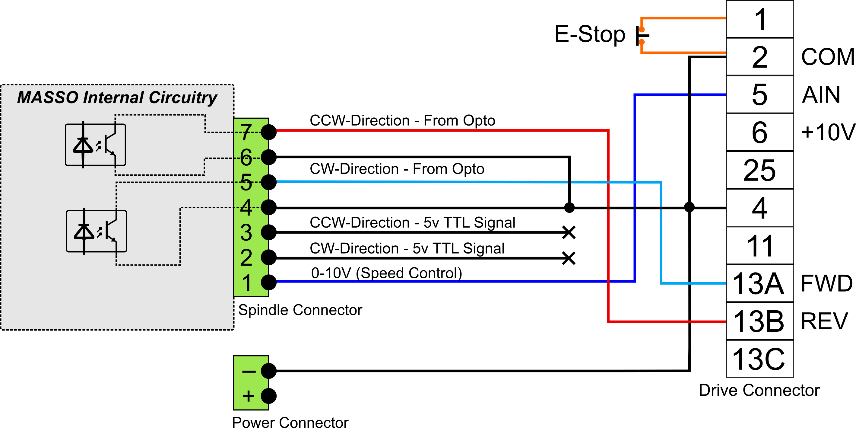
The common elements inside a wiring diagram are ground, power, wire and connection, output devices, switches, resistors, logic gate, lights, etc. A wiring diagram is a kind of schematic which uses abstract pictorial symbols to demonstrate every one of the interconnections of components inside a system. Wiring diagrams for 3dtek vfd spindle and aio card. Three phase vfd control motor forward and reverse. Vfd wiring diagram showing power in out and control device scientific file jpg probotix wiki start stop electrical4u allen bradley powerflex instrumentationtools variable frequency drive for constant pressure water supply controlling vfds with manual inputs technical articles unitronics quick guide help desk software by vision helpdesk 3 phase induction motor.
 Source: wiring.hpricorpcom.com
Few days ago gohz made a 24v 2000w power inverter in home sharing some design schematics and circuit diagrams. Connect or do wiring as per vfd side drawing, you take +24 v from the vfd pcb directly. Wiring vfd motor control circuit diagram. Please read important notes at bottom before powering up the vfd!!!! Application note ap0400076en vfd wiring best practices effective july 2014 2 eaton corporation www.eaton.com control wiring similar consideration need to be taken when looking at the control wiring.
 Source: musicpopblogg.blogspot.com
The rest of page 8 of this plc wiring diagram is related to some interlocks or conditions and also the power to the fan of the electric motor. The vfds showed in the video are the d720s (230v single phase) and the d720 (230v three phase). Wiring diagrams for 3dtek vfd spindle and aio card. This is beneficial for both the individuals and for professionals who’re looking to find out more on how to set up a operating surroundings. Check if the operator buttons are all right.
 Source: wiringschemas.blogspot.com
Wiring diagrams for 3dtek vfd spindle and aio card. Vfd start stop wiring diagram. 8 16 2020 vfd control wiring diagram wiring diagram is a simplified all right pictorial representation of an electrical circuit it shows the components of the circuit as simplified shapes and the. This is beneficial for both the individuals and for professionals who’re looking to find out more on how to set up a operating surroundings. The rest of page 8 of this plc wiring diagram is related to some interlocks or conditions and also the power to the fan of the electric motor.
 Source: worldvisionsummerfest.com
Check if the optional components you ordered are contained. K1 no1, pb3, pb4, pb5 should be of potential free contact. Internal circuit of variable frequency drive how to build a 3 phase vfd single the schematic or diagram svc can refer driver prototype set triac for ac induction motors general vsi working principle your electrical make metso brief explaination about three control motor forward basics diagrams with plc. Nameplate description of hy series inverter Vfd wiring diagram showing power in out and control device scientific file jpg probotix wiki start stop electrical4u allen bradley powerflex instrumentationtools.
This site is an open community for users to do submittion their favorite wallpapers on the internet, all images or pictures in this website are for personal wallpaper use only, it is stricly prohibited to use this wallpaper for commercial purposes, if you are the author and find this image is shared without your permission, please kindly raise a DMCA report to Us.
If you find this site helpful, please support us by sharing this posts to your own social media accounts like Facebook, Instagram and so on or you can also save this blog page with the title vfd wiring diagram by using Ctrl + D for devices a laptop with a Windows operating system or Command + D for laptops with an Apple operating system. If you use a smartphone, you can also use the drawer menu of the browser you are using. Whether it’s a Windows, Mac, iOS or Android operating system, you will still be able to bookmark this website.
Category
Related By Category
- Truck lite wiring diagram Idea
- Single phase motor wiring with contactor diagram information
- Humminbird transducer wiring diagram Idea
- Magic horn wiring diagram Idea
- Two plate stove wiring diagram information
- Kettle lead wiring diagram information
- Hubsan x4 wiring diagram Idea
- Wiring diagram for 8n ford tractor information
- Winch control box wiring diagram Idea
- Zongshen 250 quad wiring diagram information