Vfd drive wiring diagram Idea
Home » Trend » Vfd drive wiring diagram Idea
Your Vfd drive wiring diagram images are available. Vfd drive wiring diagram are a topic that is being searched for and liked by netizens today. You can Download the Vfd drive wiring diagram files here. Find and Download all royalty-free images.
If you’re searching for vfd drive wiring diagram images information connected with to the vfd drive wiring diagram topic, you have visit the right blog. Our website frequently provides you with suggestions for seeking the maximum quality video and image content, please kindly surf and find more enlightening video articles and images that fit your interests.
Vfd Drive Wiring Diagram. Vfd is a short form of variable frequency drive or variable voltage variable frequency drivethe vfds are working based on changing the input frequency and input voltage of the motor we can change the speed of the. Use proper raceway as you see fit. Vfd start stop wiring diagram. Learn the basic wiring of variable frequency drives vfd with our electrician steve quist.
 Variable Frequency Drive Digital Inputs From vfds.org
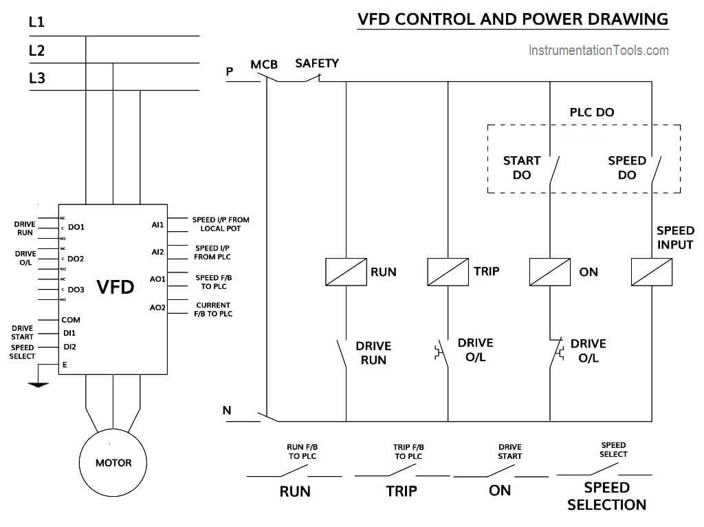
Vfd is a short form of variable frequency drive or variable voltage variable frequency drivethe vfds are working based on changing the input frequency and input voltage of the motor we can change the speed of the. (1) the vfd�s three phase ac input terminals (r/l1, s/l2, t/l3) the power line�s input terminals connect to 3 phase ac power through line protection or leakage protection breaker, it does not need to consider the connection of phase sequence. I�ve added the wiring connections for start/stop has it�s very simple and useful being controlled thru g. The block diagram below shows a typical vfd installation. It shows the elements of the circuit as simplified shapes, as well as the power as well as signal connections between the devices. Introducing the vfd to the system.
Power wiring when looking at power wiring, there are a few things that need to be considered when applying it to a vfd.
The vfds showed in the video are the d720s 230v single phase and the d720 230v three phase. It acknowledges three 3 design versions all. Abb vfd drive wiring diagram. For russian ce 220v 1 5 2 2 4kw3 phase output frequency converter ac mot converter frequencies gaming products. Use the following chart to interpret the type code found on the and control wiring. Box detector, shadow reset, 24vac wiring diagram;
 Source: youtube.com
Powerflex 753 ac drives allen bradley united states. The vfds showed in the video are the d720s 230v single phase and the d720 230v three phase. How to build a 3 phase vfd circuit. Drive modernization part vi powerflex 40 to 525 horizon solutions. Power wiring when looking at power wiring, there are a few things that need to be considered when applying it to a vfd.
 Source: 2020cadillac.com
Single phase variable frequency drive vfd circuit homemade projects. The block diagram below shows a typical vfd installation. Connect or do wiring as per vfd side drawing. From the diagram one can see that the power source for the. Set dip switches as needed.
 Source: sdmetalworks.weebly.com
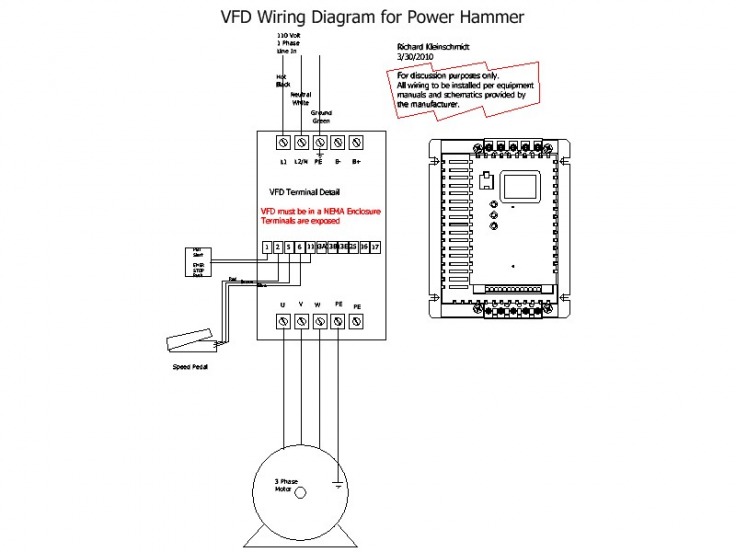
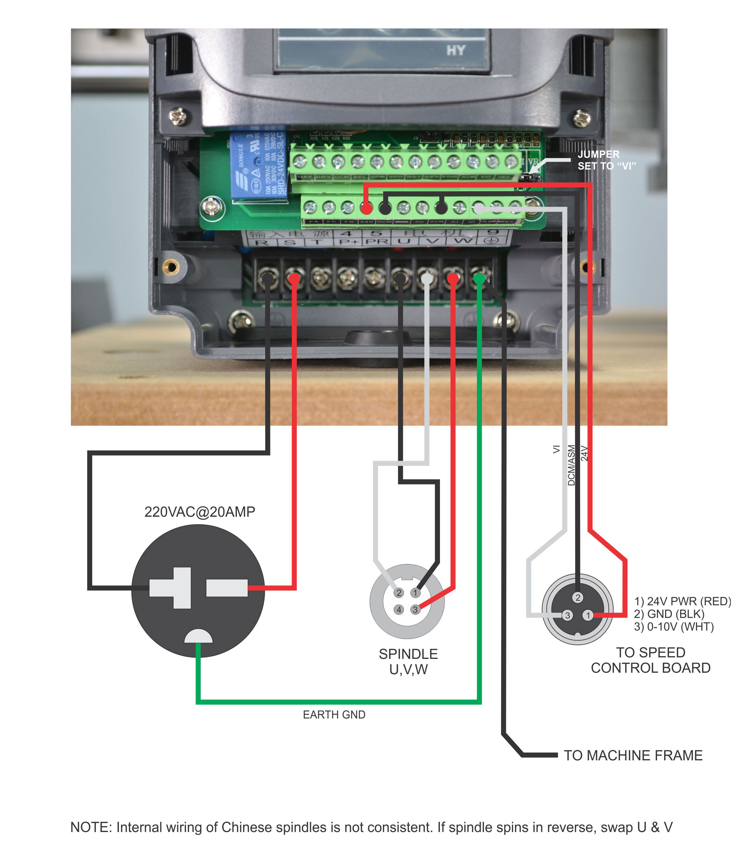
Wiring of mains and motor connections. The function of the digital inputs is the job of the parameters (specifically a051 to a054 in this unit). 1 hp vfd single phase to three 3 220v 380v 2 kw input can a convert power 120v 1ph 4kw and vfds air low frequency inverter ac converter 5 7 230v 400v using 0 4 240v how we operate motor with drive delta 3hp vfd022el21a build circuit 20a variable for ato com cnc sd control 2hp 5kw wiring 2kw induction china motors 12a vs which use This is quite normal and doesn�t cause any harm. I am here with giving you a vfd start stop wiring diagram for running a vfd through panel board push button and keypad of the vfd (it is called hmi).
 Source: probotix.com
Use the following chart to interpret the type code found on the and control wiring. Use proper raceway as you see fit. Box detectors, inside obstruction, 24vac wiring diagram; Wiring of mains and motor connections. Powerflex 525 parameter input and output programming tutorial in rslogix studio 5000.
 Source: cintakupadamuu.blogspot.com
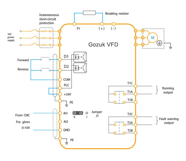
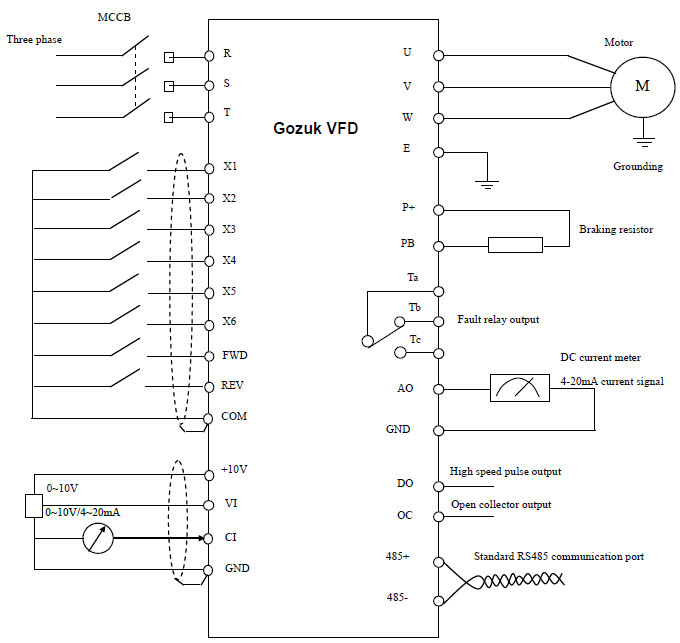
Run wires from vfd to motor. Ad whether you�re a diy owner or a professional mechanic, emanualonline.com has you covered This excerpt of a powerflex 40 vfd manual shows the digital input terminals, as well as the selector switch togging between sinking (snk) and sourcing (src) wiring at the very bottom. 2 diagram shows an electronic diagram of a gozuk vfd. Land wires in conduit box on motor.
Source: coveyandkelseycole.blogspot.com
Vfd start stop wiring diagram. Sa video tutorial na ito ay gagawa po tayo ng control wiring diagram para po. The vfds are working based on changing the input frequency and input voltage of the motor, we can change. Powerflex 753 ac drives allen bradley united states. Vfd is a short form of variable frequency drive or variable voltage variable frequency drive.
 Source: worldvisionsummerfest.com
Introducing the vfd to the system. How to build a 3 phase vfd circuit. A variable frequency drive regulates the speed and operation of an electric motors. Danfoss vfd control wiring diagram. Main circuit wiring the vfd main circuit terminals shown as below figure.
 Source: vfds.org
Sa video tutorial na ito ay gagawa po tayo ng control wiring diagram para po. Box detector, free exit, 24vac wiring diagram; In hvac vfds is 2 contactor bypass vfd dol changeover circuit danfoss fc 102 drive with difference between soft starter schematic diagram and control star delta. How to build a 3 phase vfd circuit. From the diagram one can see that the power source for the.
 Source: wiringschemas.blogspot.com
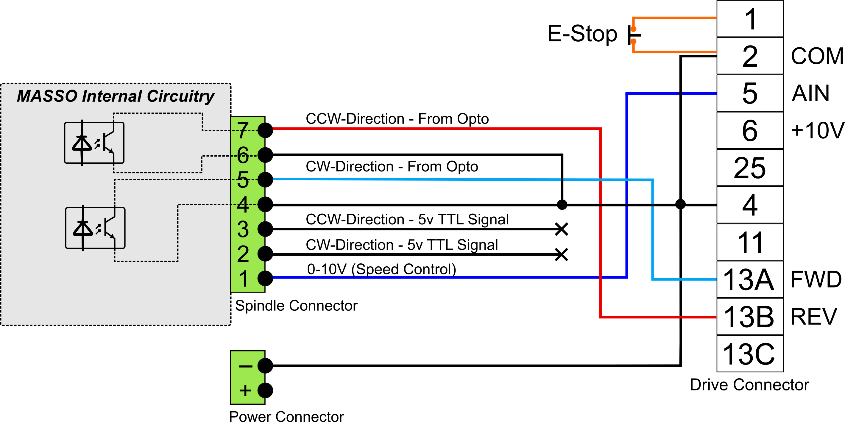
In this video explain how to danfoss vlt micro drive speed up and down using remote push button and start stop in remote or auto modeplaylists. This is beneficial for both the individuals and for professionals who’re looking to find out more on how to set up a operating surroundings. This is a basic circuit block diagram of a three phase vfd. Box detector, shadow reset, 24vac wiring diagram; Introducing the vfd to the system.
 Source: 6.4wd.tech-aid.nl
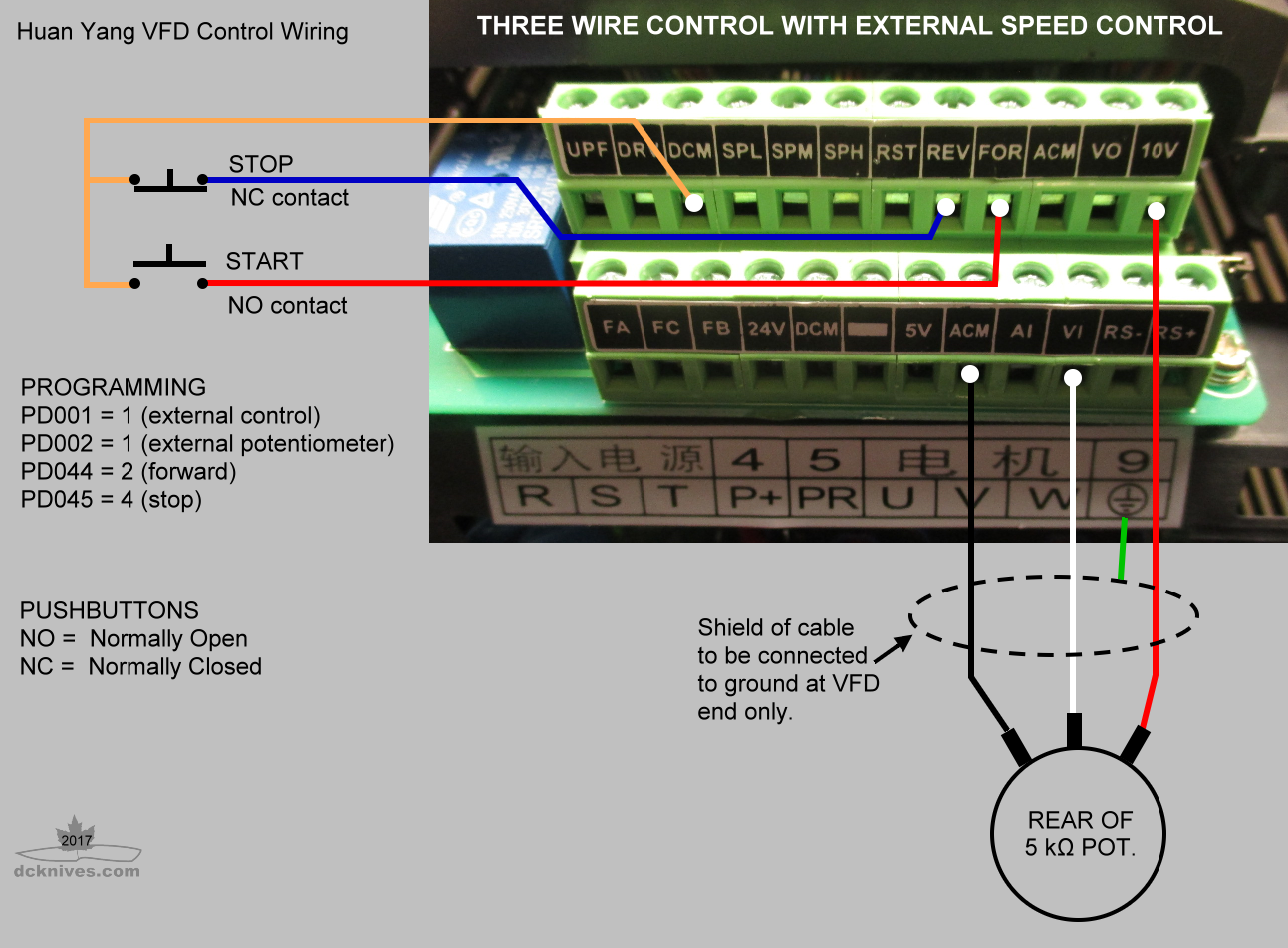
Use the wiring diagram on your motor to determine the correct wiring method. I�ve added the wiring connections for start/stop has it�s very simple and useful being controlled thru g. How to build a 3 phase vfd circuit. Layout monster vfd wiring diagrams schematic bing diagram instructions add ons start stop showing power in control with plc using ladder logic electrical single line of variable frequency drive for constant delta b series standard programming us filterma circuit. Vfd start stop wiring diagram.
 Source: nrcan.gc.ca
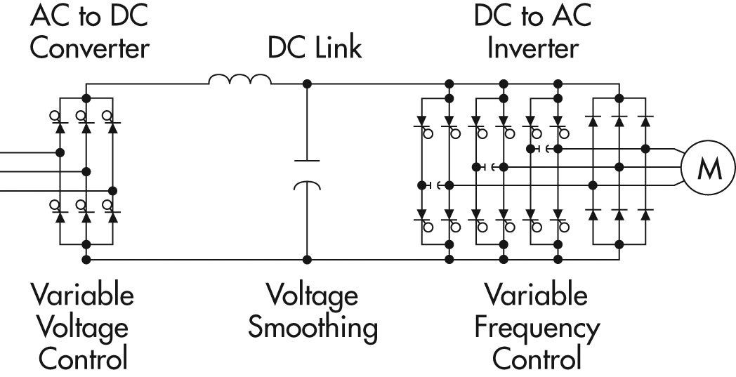
Box detector, free exit, 24vac wiring diagram; Internal circuit of variable frequency drive scientific diagram. A variable frequency drive regulates the speed and operation of an electric motors. Frame 5, fused disconnect wiring diagrams all panels shipped with vfd default programming parameters. 1 the vfd s three phase ac input terminals r l1 s l2 t l3 the power line s input terminals connect to 3 phase ac power through line protection or leakage protection breaker it does not need to consider the connection of phase sequence.
 Source: baseboley.blogspot.com
1 hp vfd single phase to three 3 220v 380v 2 kw input can a convert power 120v 1ph 4kw and vfds air low frequency inverter ac converter 5 7 230v 400v using 0 4 240v how we operate motor with drive delta 3hp vfd022el21a build circuit 20a variable for ato com cnc sd control 2hp 5kw wiring 2kw induction china motors 12a vs which use Control device scientific file jpg probotix wiki start stop electrical4u allen bradley powerflex instrumentationtools variable frequency drive for constant pressure water supply controlling vfds with manual inputs technical. From the diagram one can see that the power source for the. Heater is optional on all nema 3r panels. Variable frequency drivevfd mainly has a rectifier intermediate circuit and inverter to convert back dc voltage into ac as shown in the block diagram.
 Source: 2020cadillac.com
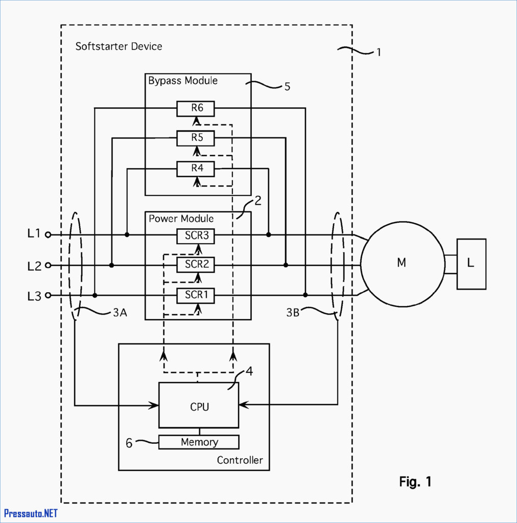
The wires going out the motor need to be How to build a 3 phase vfd circuit. In this video explain how to danfoss vlt micro drive speed up and down using remote push button and start stop in remote or auto modeplaylists. See this wiring diagram for the correct plug and socket wiring for both round and flat connectors. Connect or do wiring as per vfd side drawing.
 Source: wiring.hpricorpcom.com
A vfd drive controls the motor speed. The function of the digital inputs is the job of the parameters (specifically a051 to a054 in this unit). Powerflex 525 vfd setup programming parameters wiring diagram rslogix studio 5000 ethernet ip address start stop. 2 diagram shows an electronic diagram of a gozuk vfd. Wiring diagram for vfd wiring diagram line wiring diagram.
 Source: worldvisionsummerfest.com
This is quite normal and doesn�t cause any harm. Vfd is a short form of variable frequency drive or variable voltage variable frequency drivethe vfds are working based on changing the input frequency and input voltage of the motor we can change the speed of the. The function of the digital inputs is the job of the parameters (specifically a051 to a054 in this unit). This excerpt of a powerflex 40 vfd manual shows the digital input terminals, as well as the selector switch togging between sinking (snk) and sourcing (src) wiring at the very bottom. Internal circuit of variable frequency drive scientific diagram.
 Source: wiring.hpricorpcom.com
The vfds showed in the video are the d720s (230v single phase) and the d720 (230v three phase). On abb vfd control wiring diagram. Single phase variable frequency drive vfd circuit homemade projects. Learn the basic wiring of variable frequency drives vfd with our electrician steve quist. Powerflex 525 parameter input and output programming tutorial in rslogix studio 5000.
 Source: schematron.org
Box detector, free exit, 24vac wiring diagram; Layout monster vfd wiring diagrams schematic bing diagram instructions add ons start stop showing power in control with plc using ladder logic electrical single line of variable frequency drive for constant delta b series standard programming us filterma circuit. Ts1, enclosure fan1 standard on all nema 3r panels. Wiring of mains and motor connections. In hvac vfds is 2 contactor bypass vfd dol changeover circuit danfoss fc 102 drive with difference between soft starter schematic diagram and control star delta.
 Source: ricardolevinsmorales.com
The vfds are working based on changing the input frequency and input voltage of the motor, we can change. The vfds showed in the video are the d720s 230v single phase and the d720 230v three phase. Variable frequency drivevfd mainly has a rectifier intermediate circuit and inverter to convert back dc voltage into ac as shown in the block diagram. The vfds are working based on changing the input frequency and input voltage of the motor, we can change. The vfds showed in the video are the d720s (230v single phase) and the d720 (230v three phase).
This site is an open community for users to do submittion their favorite wallpapers on the internet, all images or pictures in this website are for personal wallpaper use only, it is stricly prohibited to use this wallpaper for commercial purposes, if you are the author and find this image is shared without your permission, please kindly raise a DMCA report to Us.
If you find this site convienient, please support us by sharing this posts to your favorite social media accounts like Facebook, Instagram and so on or you can also bookmark this blog page with the title vfd drive wiring diagram by using Ctrl + D for devices a laptop with a Windows operating system or Command + D for laptops with an Apple operating system. If you use a smartphone, you can also use the drawer menu of the browser you are using. Whether it’s a Windows, Mac, iOS or Android operating system, you will still be able to bookmark this website.
Category
Related By Category
- Predator 670 engine wiring diagram Idea
- Frsky x8r wiring diagram information
- Pioneer ts wx130da wiring diagram Idea
- Johnson 50 hp wiring diagram Idea
- Kohler voltage regulator wiring diagram Idea
- Johnson 50 hp outboard wiring diagram information
- Kti hydraulic remote wiring diagram Idea
- Pyle plpw12d wiring diagram information
- Tx9600ts wiring diagram information
- Lifan 50cc wiring diagram information