Vfd control wiring diagram Idea
Home » Trend » Vfd control wiring diagram Idea
Your Vfd control wiring diagram images are available. Vfd control wiring diagram are a topic that is being searched for and liked by netizens today. You can Get the Vfd control wiring diagram files here. Get all royalty-free photos.
If you’re searching for vfd control wiring diagram images information related to the vfd control wiring diagram topic, you have visit the ideal site. Our website frequently provides you with suggestions for downloading the maximum quality video and image content, please kindly search and find more informative video articles and images that fit your interests.
Vfd Control Wiring Diagram. We strongly recommend using a certified electrician. The vfds showed in the video are the d720s 230v single phase and the d720 230v three phase. Set dip switches as needed. 1 the vfd s three phase ac input terminals r l1 s l2 t l3 the power line s input terminals connect to 3 phase ac power through line protection or leakage protection breaker it does not need to consider the connection of phase sequence.
 Beginner VFD Wiring From practicalmachinist.com
Use the following chart to interpret the type code found on the and control wiring. Three phase vfd control motor forward and reverse. By ehtel quijano | august 23, 2020. Vfd start stop wiring diagram: Wiring vfd motor control circuit diagram. Internal circuit of variable frequency drive how to build a 3 phase vfd single the schematic or diagram svc can refer driver prototype set triac for ac induction motors general vsi working principle your electrical make metso brief explaination about three control motor forward basics diagrams with plc.
Vfd start stop wiring diagram:
A vfd drive controls the motor speed. The vfd main circuit terminals shown as below figure. Vfd is a short form of variable frequency drive or variable voltage variable frequency drive. Danfoss vfd wiring diagram wiring diagram data schema pioneer avic n1 wiring diagram. From the diagram one can see that the power source for the. (1) the vfd�s three phase ac input terminals (r/l1, s/l2, t/l3) the power line�s input terminals connect to 3 phase ac power through line protection or leakage protection breaker, it does not need to consider the connection of phase sequence.
 Source: wholefoodsonabudget.com
Vfd wiring diagram showing power in 1 vfd 2 motors variable frequency drive for constant. Application note ap0400076en vfd wiring best practices effective july 2014 2 eaton corporation www.eaton.com control wiring similar consideration need to be taken when looking at the control wiring. (1) the vfd�s three phase ac input terminals (r/l1, s/l2, t/l3) the power line�s input terminals connect to 3 phase ac power through line protection or leakage protection breaker, it does not need to consider the connection of phase sequence. Frame 5, 2 contactor wiring diagram m34225 all panels shipped with vfd default programming parameters. Make sure if you have a bypass function that both the vfd and bypass mode operate the motor in the same direction.
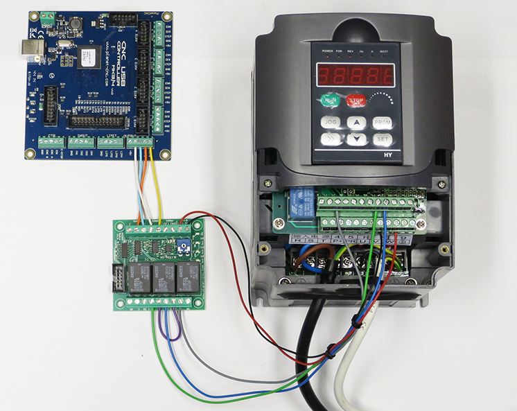 Source: grazisurfistinha.blogspot.com
From the diagram one can see that the power source for the. Frame 5, 2 contactor wiring diagram m34225 all panels shipped with vfd default programming parameters. The vfds showed in the video are the d720s 230v single phase and the d720 230v three phase. This diagram shows the wires that supply power to the vfd the wires that provide voltage from the vfd to the motor and all the necessary input and output signals that. Vfd start stop wiring diagram:
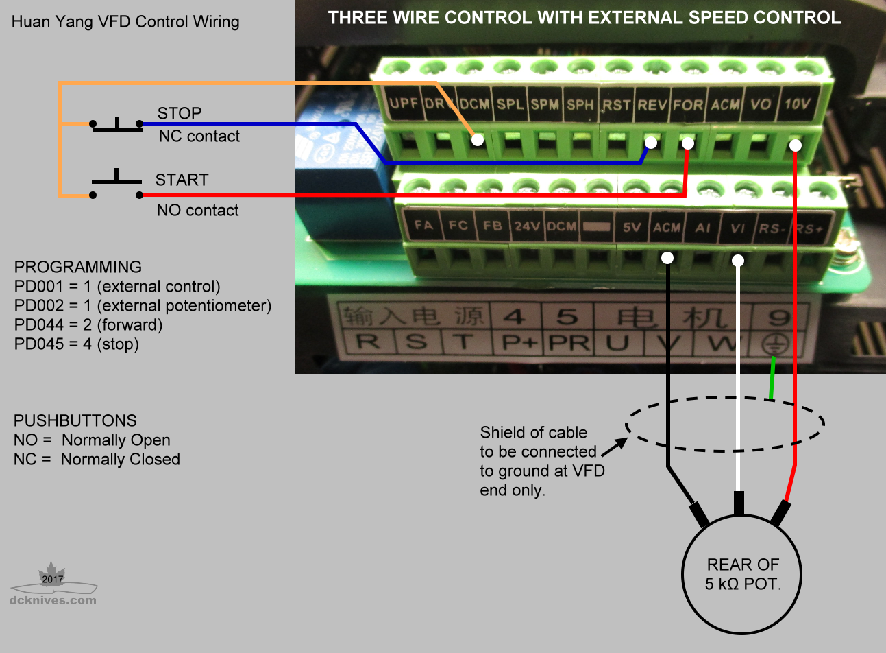 Source: 6.4wd.tech-aid.nl
The vfds showed in the video are the d720s (230v single phase) and the d720 (230v three phase). Three phase vfd control motor forward and reverse. Application note ap0400076en vfd wiring best practices effective july 2014 2 eaton corporation www.eaton.com control wiring similar consideration need to be taken when looking at the control wiring. The vfds showed in the video are the d720s (230v single phase) and the d720 (230v three phase). Installation requirements wiring basic wiring diagram • connect the delta jumper cable #102561) to the existing wiring on the spindle control board as.
 Source: cintakupadamuu.blogspot.com
On abb vfd control wiring diagram. By ehtel quijano | august 23, 2020. Vfd control wiring diagram practical machinist largest manufacturing technology forum on the web. P3 non bypass mechanical layout diagram. Read or download wiring diagram for free of vfd at digivaley.com
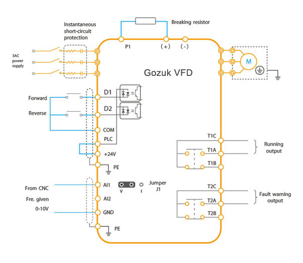 Source: vfds.org
Wiring vfd motor control circuit diagram. Vfd control panel diagram and vfd full of zip principle youtube. Typically, these will be on the same 24 vdc system as the remainder of the control system devices. Vfd control wiring diagram autocardesign. Installation requirements wiring basic wiring diagram • connect the delta jumper cable #102561) to the existing wiring on the spindle control board as.
 Source: 2020cadillac.com
1 the vfd s three phase ac input terminals r l1 s l2 t l3 the power line s input terminals connect to 3 phase ac power through line protection or leakage protection breaker it does not need to consider the connection of phase sequence. Vfd control wiring diagram practical machinist largest manufacturing technology forum on the web. Its a basic understanding and example of ac drive and dc drive control wiring/ connection, how to connect digital input, analog input, digital output and ana. Three phase vfd control motor forward and reverse. Ts1, enclosure fan1 standard on all nema 3r panels.
 Source: probotix.com
Danfoss vfd wiring diagram wiring diagram data schema pioneer avic n1 wiring diagram. Typically, these will be on the same 24 vdc system as the remainder of the control system devices. Check connections of l1, l2, l3; On abb vfd control wiring diagram. Read or download wiring diagram for free of vfd at digivaley.com
 Source: worldvisionsummerfest.com
The vfds are working based on changing the input frequency and input voltage of the motor, we can change. P3 non bypass mechanical layout diagram. The installation guide is intended for use by qualified personnel. Three phase vfd control motor forward and reverse. Internal circuit of variable frequency drive how to build a 3 phase vfd single the schematic or diagram svc can refer driver prototype set triac for ac induction motors general vsi working principle your electrical make metso brief explaination about three control motor forward basics diagrams with plc.
 Source: practicalmachinist.com
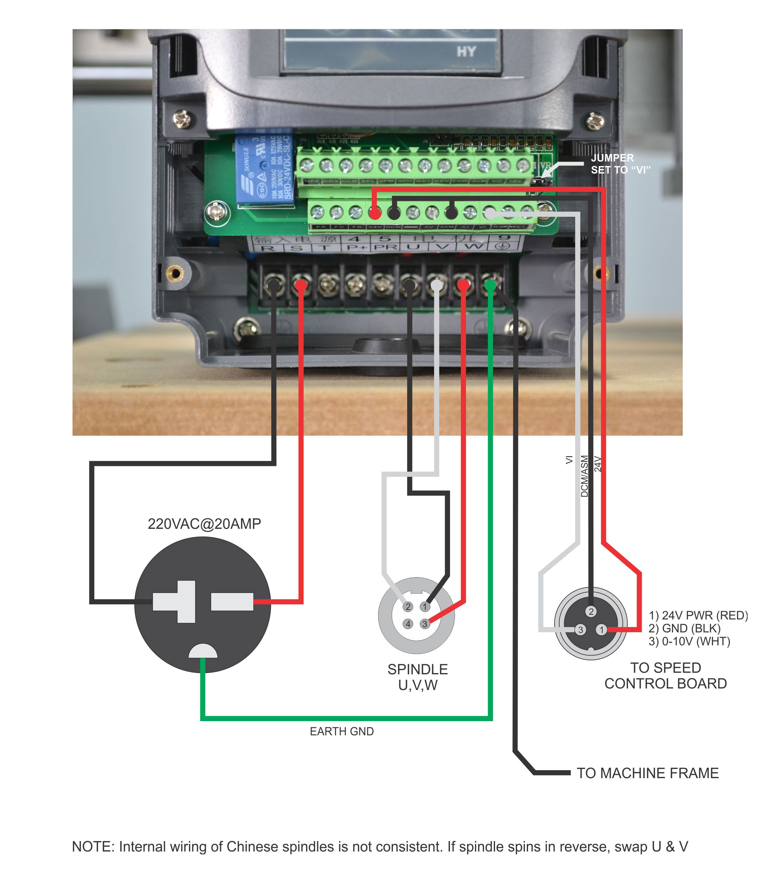
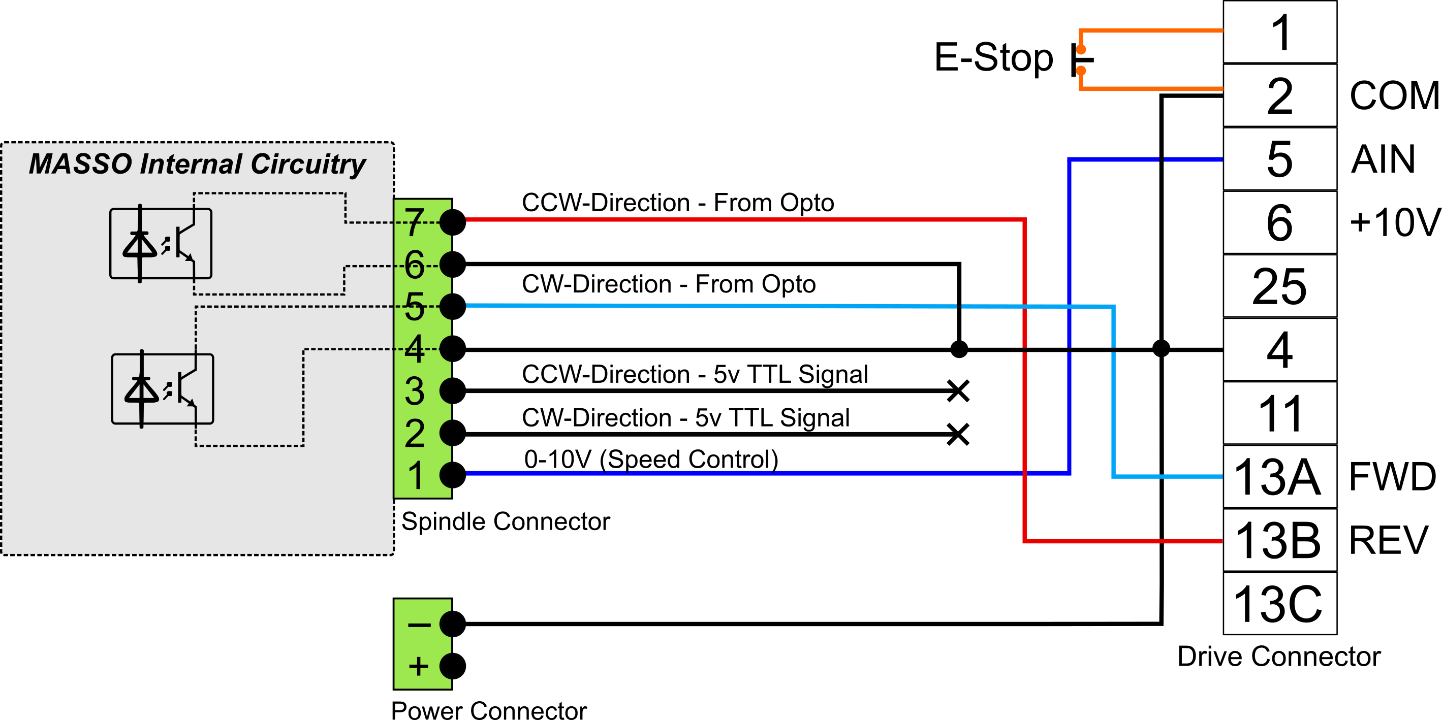
I have included an image of the motor wiring diagram from the vfd manual below. Oleh anonim april 18, 2020 posting komentar. This diagram shows the wires that supply power to the vfd, the wires that provide voltage from the vfd to the motor, and all the necessary input and output signals that the vfd needs for operation. Three phase vfd control motor forward and reverse. Vfd control wiring diagram practical machinist largest manufacturing technology forum on the web.
 Source: masso.com.au
A variable frequency drive regulates the speed and operation of an electric motors. Vfd motor control circuit diagram pdf. By ehtel quijano | august 23, 2020. Vfd is a short form of variable frequency drive or variable voltage variable frequency drive. We strongly recommend using a certified electrician.
 Source: musicpopblogg.blogspot.com
Vfd installation instructions the block diagram below shows a typical vfd installation. Danfoss vfd control wiring diagram. Learn the basic wiring of variable frequency drives vfd with our electrician steve quist. The vfd main circuit terminals shown as below figure. We strongly recommend using a certified electrician.
 Source: rabbitcarrr.blogspot.com
This is beneficial for both the individuals and for professionals who’re looking to find out more on how to set up a operating surroundings. Vfd control panel diagram and vfd full of zip principle youtube. Varaible speed drives for motor driven fire pumps lenze wiring diagrams wiring diagram dash vfd circuit diagram wiring diagram hvac control wiring wiring diagram 500 vfd wiring for dummies vfd motor connection star or delta. Ts1, enclosure fan1 standard on all nema 3r panels. The vfd main circuit terminals shown as below figure.
 Source: wiring.hpricorpcom.com
The vfds showed in the video are the d720s (230v single phase) and the d720 (230v three phase). (1) the vfd�s three phase ac input terminals (r/l1, s/l2, t/l3) the power line�s input terminals connect to 3 phase ac power through line protection or leakage protection breaker, it does not need to consider the connection of phase sequence. Every vfd will include a set of terminals allowing a user to connect i/o wires. Learn the basic wiring of variable frequency drives vfd with our electrician steve quist. Controlled environment that is suitable for the selected enclosure.
 Source: wiringschemas.blogspot.com
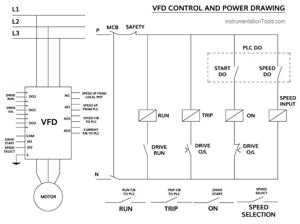
Vfd installation instructions the block diagram below shows a typical vfd installation. Danfoss vfd control wiring diagram. This diagram shows the wires that supply power to the vfd, the wires that provide voltage from the vfd to the motor, and all the necessary input and output signals that the vfd needs for operation. A vfd drive controls the motor speed. (1) the vfd�s three phase ac input terminals (r/l1, s/l2, t/l3) the power line�s input terminals connect to 3 phase ac power through line protection or leakage protection breaker, it does not need to consider the connection of phase sequence.
 Source: ricardolevinsmorales.com
On abb vfd control wiring diagram. The block diagram below shows a typical vfd installation. It shows the components of the circuit as simplified shapes and the talent and signal associates in the midst of the devices. Frame 5, 2 contactor wiring diagram m34225 all panels shipped with vfd default programming parameters. Learn the basic wiring of variable frequency drives / vfd with our electrician steve quist.
 Source: wiring.hpricorpcom.com
Vfd start stop wiring diagram: Wiring vfd motor control circuit diagram. Vfd control wiring diagram autocardesign. Vfd control wiring diagram practical machinist largest manufacturing technology forum on the web. The vfds showed in the video are the d720s (230v single phase) and the d720 (230v three phase).
![[EH_2405] Huanyang Vfd Control Wiring Diagram Huanyang Get [EH_2405] Huanyang Vfd Control Wiring Diagram Huanyang Get](https://static-cdn.imageservice.cloud/75622/amazoncom-vfd-110v-22kw-3hp-variable-frequency-cnc-motor-drive.jpg) Source: tzici.ungo.awni.eopsy.peted.oidei.vira.mohammedshrine.org
Source: tzici.ungo.awni.eopsy.peted.oidei.vira.mohammedshrine.org
Installation requirements wiring basic wiring diagram • connect the delta jumper cable #102561) to the existing wiring on the spindle control board as. It shows the components of the circuit as simplified shapes and the talent and signal associates in the midst of the devices. Danfoss vfd control wiring diagram. From the diagram one can see that the power source for the. A vfd drive controls the motor speed.
![[DIAGRAM] Abb Vfd Control Wiring Diagram Free Download [DIAGRAM] Abb Vfd Control Wiring Diagram Free Download](https://i.ytimg.com/vi/SR7NgB_sSlE/maxresdefault.jpg) Source: diagramfireplace.cdu-brackwede.de
Source: diagramfireplace.cdu-brackwede.de
P3 non bypass mechanical layout diagram. On abb vfd control wiring diagram. Ts1, enclosure fan1 standard on all nema 3r panels. We strongly recommend using a certified electrician. Vfd motor control circuit diagram, related gallery:
This site is an open community for users to share their favorite wallpapers on the internet, all images or pictures in this website are for personal wallpaper use only, it is stricly prohibited to use this wallpaper for commercial purposes, if you are the author and find this image is shared without your permission, please kindly raise a DMCA report to Us.
If you find this site value, please support us by sharing this posts to your own social media accounts like Facebook, Instagram and so on or you can also bookmark this blog page with the title vfd control wiring diagram by using Ctrl + D for devices a laptop with a Windows operating system or Command + D for laptops with an Apple operating system. If you use a smartphone, you can also use the drawer menu of the browser you are using. Whether it’s a Windows, Mac, iOS or Android operating system, you will still be able to bookmark this website.
Category
Related By Category
- Predator 670 engine wiring diagram Idea
- Frsky x8r wiring diagram information
- Pioneer ts wx130da wiring diagram Idea
- Johnson 50 hp wiring diagram Idea
- Kohler voltage regulator wiring diagram Idea
- Johnson 50 hp outboard wiring diagram information
- Kti hydraulic remote wiring diagram Idea
- Pyle plpw12d wiring diagram information
- Tx9600ts wiring diagram information
- Lifan 50cc wiring diagram information