Variable frequency drive wiring diagram information
Home » Trend » Variable frequency drive wiring diagram information
Your Variable frequency drive wiring diagram images are ready. Variable frequency drive wiring diagram are a topic that is being searched for and liked by netizens now. You can Find and Download the Variable frequency drive wiring diagram files here. Find and Download all free images.
If you’re looking for variable frequency drive wiring diagram pictures information related to the variable frequency drive wiring diagram interest, you have visit the ideal blog. Our site always gives you hints for downloading the highest quality video and picture content, please kindly hunt and locate more enlightening video articles and images that match your interests.
Variable Frequency Drive Wiring Diagram. To purchase any saftronics drives or information regarding saftronics drives and accessories, contact us at: A variable frequency drive vfd is a type of motor controller that drives an electric motor by varying the frequency and voltage supplied to the electric motor. Nelson1805 (electrical) 4 jun 10 10:21. The transistors in the pwm.
 460V Variable Frequency Drives From anaheimautomation.com
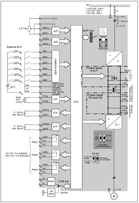
Make sure to connect the ground terminal to an appropriate safety ground. The post discusses a single phase variable frequency drive circuit or a vfd circuit for controlling ac motor sped without affecting their operational specifications. The block diagram below shows a typical vfd installation. Download variable frequency drive wiring diagram pdf vfd schematic diagram and control. O motor control pulse width modulation pwm outputs, provides a 24v dc signal that can be used to drive an electrically commutated motor ecm at a programmed duty cycle. To purchase any saftronics drives or information regarding saftronics drives and accessories, contact us at:
October 5, 2020 at 6:02 pm.
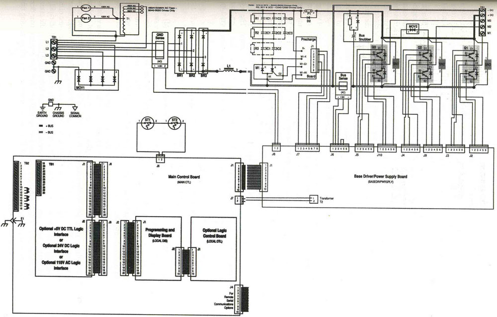
A variable frequency drive (vfd) is a type of motor controller that drives an electric motor by varying the frequency and voltage supplied to the electric motor. Nelson1805 (electrical) 4 jun 10 10:21. From the diagram one can see that the power source for the. The transistors in the pwm. Service and repair manual toyota yaris 2016. A basic vfd system generally consists of an ac motor, a controller, and an operator interface.
 Source: prsteyer.blogspot.com
A variable frequency drive vfd is a type of motor controller that drives an electric motor by varying the frequency and voltage supplied to the electric motor. Nelson1805 (electrical) 4 jun 10 10:21. The variable frequency drive circuit guarantees that excess current from the motor when operating, which helps keep utility costs down. October 5, 2020 at 6:02 pm. Please don�t connect shifting capacitor or lc/rc noise filter with output loop.
 Source: ebay.com
This includes wiring diagrams as well. Make sure to connect the ground terminal to an appropriate safety ground. Collection of abb vfd wiring diagram. Without any knowledge of frequency converters,. The transistors in the pwm.
 Source: circuitdiagramcentre.blogspot.com
O motor control pulse width modulation pwm outputs, provides a 24v dc signal that can be used to drive an electrically commutated motor ecm at a programmed duty cycle. These are specially designed 2 channel safety switches wired into safety relays. Variable frequency drive wiring diagram benefits of variable speed controls 1. Vfd is a short form of variable frequency drive or variable voltage variable frequency drive. Variable frequency drives (vfd’s) • popular speed control devices used in industrial, commercial and residential applications.
 Source: dreisilker.com
The vfds are working based on changing the input frequency and input voltage of the motor, we can change. I am here with giving you a vfd start stop wiring diagram for running a vfd through panel board push button and keypad of the vfd (it is called hmi). The variable frequency drive vfd package shall contain all components required to meet the. A variable frequency drive vfd is a type of motor controller that drives an electric motor by varying the frequency and voltage supplied to the electric motor. I would put the contactor between the vfd and the motor with an auxilliary contact which starts the vfd when the contactor closes.
 Source: wiring89.blogspot.com
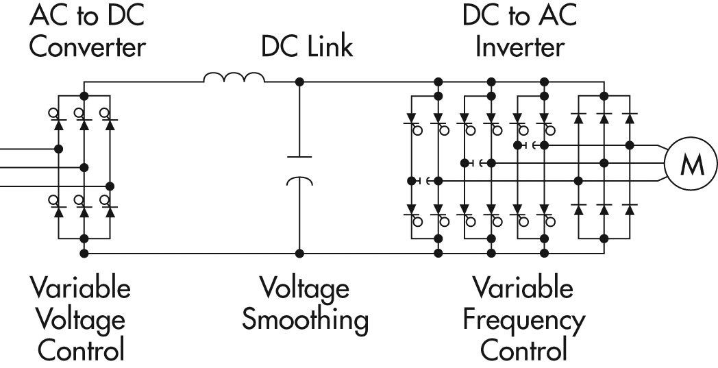
This electrical device that transforms the ac power supply frequency, the vfd circuit, comprises three parts. From the diagram one can see that the power source for the. Nelson1805 (electrical) 4 jun 10 10:21. July 25, 2021 on vfd drive wiring diagram. I would put the contactor between the vfd and the motor with an auxilliary contact which starts the vfd when the contactor closes.
 Source: nrcan.gc.ca
Please don�t connect input mains cable with output terminals of u/v/w. The vfd main circuit terminals shown as below figure. 5 — acs320 vfd location for the following units: Mount push button and indications accessories on the panel door. I would put the contactor between the vfd and the motor with an auxilliary contact which starts the vfd when the contactor closes.
 Source: vfds.org
By vallery masson on july 25, 2021. Danfoss vfd control wiring diagram. Make sure to connect the ground terminal to. Variable frequency drives presented by: Learn the basic wiring of variable frequency drives vfd with our electrician steve quist.
 Source: in.pinterest.com
I would put the contactor between the vfd and the motor with an auxilliary contact which starts the vfd when the contactor closes. Cosmos logic see appendix is used to drive the difference amplifier to provide voltage stability in this circuit. July 25, 2021 on vfd drive wiring diagram. October 5, 2020 at 6:02 pm. A variable frequency drive (vfd) is a type of motor controller that drives an electric motor by varying the frequency and voltage supplied to the electric motor.
 Source: jobselectricalengineers.blogspot.com
Danfoss vfd control wiring diagram. I would put the contactor between the vfd and the motor with an auxilliary contact which starts the vfd when the contactor closes. 5 — acs320 vfd location for the following units: Make sure to connect the ground terminal to. Within the datasheet, the user will find a lot of information about the setup of the drive.
 Source: fasttobuy.com
It may damage the vfd. Nelson1805 (electrical) 4 jun 10 10:21. Powerflex 525 variable frequency drive basic wiring and parameters. A basic vfd system generally consists of an ac motor, a controller, and an operator interface. October 5, 2020 at 6:02 pm.
 Source: pinterest.com
This is definition used in all topical discussion on this paper. This electrical device that transforms the ac power supply frequency, the vfd circuit, comprises three parts. Make sure to connect the ground terminal to. The variable frequency drive vfd package shall contain all components required to meet the. This includes wiring diagrams as well as parameters which we will be setting up shortly.
 Source: motioncontroltips.com
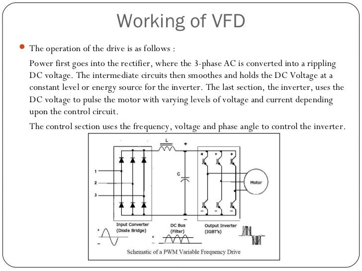
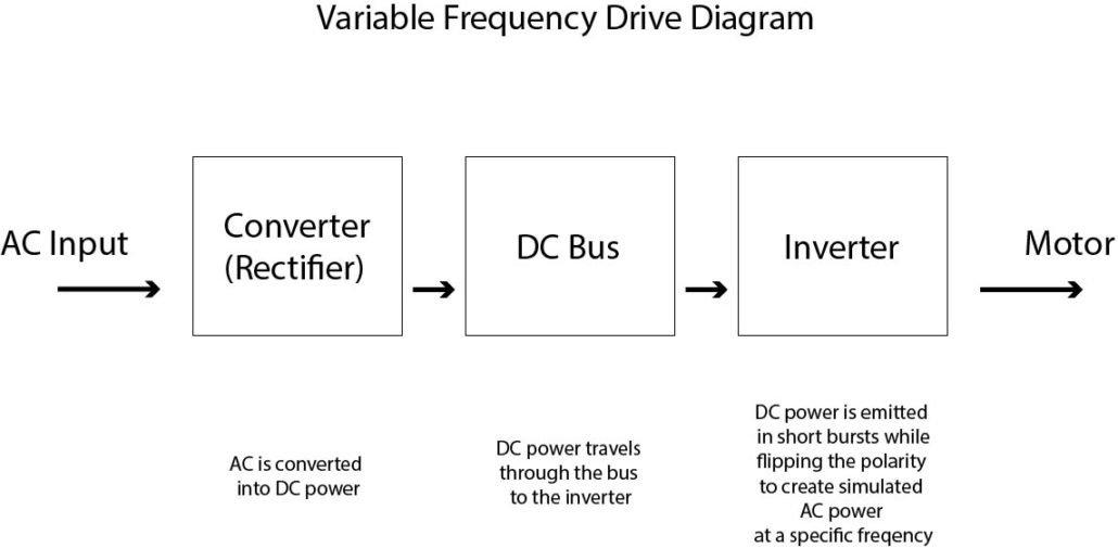
Download variable frequency drive wiring diagram pdf vfd schematic diagram and control. Cosmos logic see appendix is used to drive the difference amplifier to provide voltage stability in this circuit. The variable frequency drive circuit guarantees that excess current from the motor when operating, which helps keep utility costs down. Variable frequency drivevfd mainly has a rectifier intermediate circuit and inverter to convert back dc voltage into ac as shown in the block diagram. The vfd main circuit terminals shown as below figure.
 Source: pinterest.com
Powerflex 525 variable frequency drive basic wiring and parameters. Main circuit wiring variable frequency drive wire input to terminals l1, l2 and l3 for three phase input. Main circuit wiring variable frequency drive wire input to terminals l1 l2 and l3 for three phase input. I am here with giving you a vfd start stop wiring diagram for running a vfd through panel board push button and keypad of the vfd (it is called hmi). The variable frequency drive vfd package shall contain all components required to meet the.
 Source: anaheimautomation.com
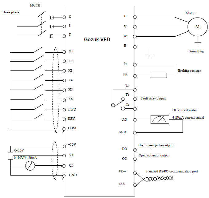
Please use screw drivers with appointed moment of force to tighten the terminals, otherwise, there is a danger of fire. It may damage the vfd. Otherwise, there is a danger of fire. The vfd main circuit terminals shown as below figure. A variable frequency drive regulates the speed and operation of an electric motors.
 Source: schematron.org
Please don�t connect shifting capacitor or lc/rc noise filter with output loop. This electrical device that transforms the ac power supply frequency, the vfd circuit, comprises three parts. This includes wiring diagrams as well. The vfds are working based on changing the input frequency and input voltage of the motor, we can change. Danfoss vfd control wiring diagram.
.png “460V Variable Frequency Drives”) Source: anaheimautomation.com
Presently, you will notice that the vfd schematic is a popular type of output transistor used for a control system. Make sure to connect the ground terminal to. Wt3 directly to the ac mains circuit power supply. The course starts with the introduction to variable frequency drives and evolution in the last few decades. I am here with giving you a vfd start stop wiring diagram for running a vfd through panel board push button and keypad of the vfd (it is called hmi).

This includes wiring diagrams as well as parameters which we will be setting up shortly. Without any knowledge of frequency converters,. A variable frequency drive regulates the speed and operation of an electric motors. The basics, variable frequency drives adjust your motor speed to closely match your output requirements, typically resulting in energy savings of 10 to 50%. Please don�t connect shifting capacitor or lc/rc noise filter with output loop.
 Source: automationprimer.com
Danfoss vfd control wiring diagram. In the below image the three sections are shown inside a block diagram. Variable frequency drives presented by: Nelson1805 (electrical) 4 jun 10 10:21. The vfd main circuit terminals shown as below figure.
This site is an open community for users to submit their favorite wallpapers on the internet, all images or pictures in this website are for personal wallpaper use only, it is stricly prohibited to use this wallpaper for commercial purposes, if you are the author and find this image is shared without your permission, please kindly raise a DMCA report to Us.
If you find this site good, please support us by sharing this posts to your preference social media accounts like Facebook, Instagram and so on or you can also save this blog page with the title variable frequency drive wiring diagram by using Ctrl + D for devices a laptop with a Windows operating system or Command + D for laptops with an Apple operating system. If you use a smartphone, you can also use the drawer menu of the browser you are using. Whether it’s a Windows, Mac, iOS or Android operating system, you will still be able to bookmark this website.
Category
Related By Category
- Predator 670 engine wiring diagram Idea
- Frsky x8r wiring diagram information
- Pioneer ts wx130da wiring diagram Idea
- Johnson 50 hp wiring diagram Idea
- Kohler voltage regulator wiring diagram Idea
- Johnson 50 hp outboard wiring diagram information
- Kti hydraulic remote wiring diagram Idea
- Pyle plpw12d wiring diagram information
- Tx9600ts wiring diagram information
- Lifan 50cc wiring diagram information