Usb sound card wiring diagram information
Home » Trending » Usb sound card wiring diagram information
Your Usb sound card wiring diagram images are available in this site. Usb sound card wiring diagram are a topic that is being searched for and liked by netizens now. You can Download the Usb sound card wiring diagram files here. Download all free photos.
If you’re searching for usb sound card wiring diagram images information connected with to the usb sound card wiring diagram keyword, you have visit the right blog. Our website frequently provides you with suggestions for seeing the highest quality video and image content, please kindly search and locate more enlightening video articles and graphics that match your interests.
Usb Sound Card Wiring Diagram. The hub can detect the attachment or detachment of devices in each port of the hub. Be sure you set the volume control and recording control sliders and check boxes for the sound card as noted on the schematic. Block diagram of a sound card scientific. 3 x 3.5mm ended cables with tinned wire ends on one end of each of the cables.
 Help setting up USB Sound with vox App_rptusers From community.allstarlink.org
Front 45 degrees, back 120 degrees = option 2. A radio cable with the appropriate connector for your radio was supplied with the signalink usb for this purpose. Here you can have an idea of the ground wirings. The circuit can handle up to 48khz sampling frequency. It also distributes power to all the devices connected to it and also detects low speed and full speed devices. The usb hub is used to connect many devices to the pc using a single usb connector.
A radio cable with the appropriate connector for your radio was supplied with the signalink usb for this purpose.
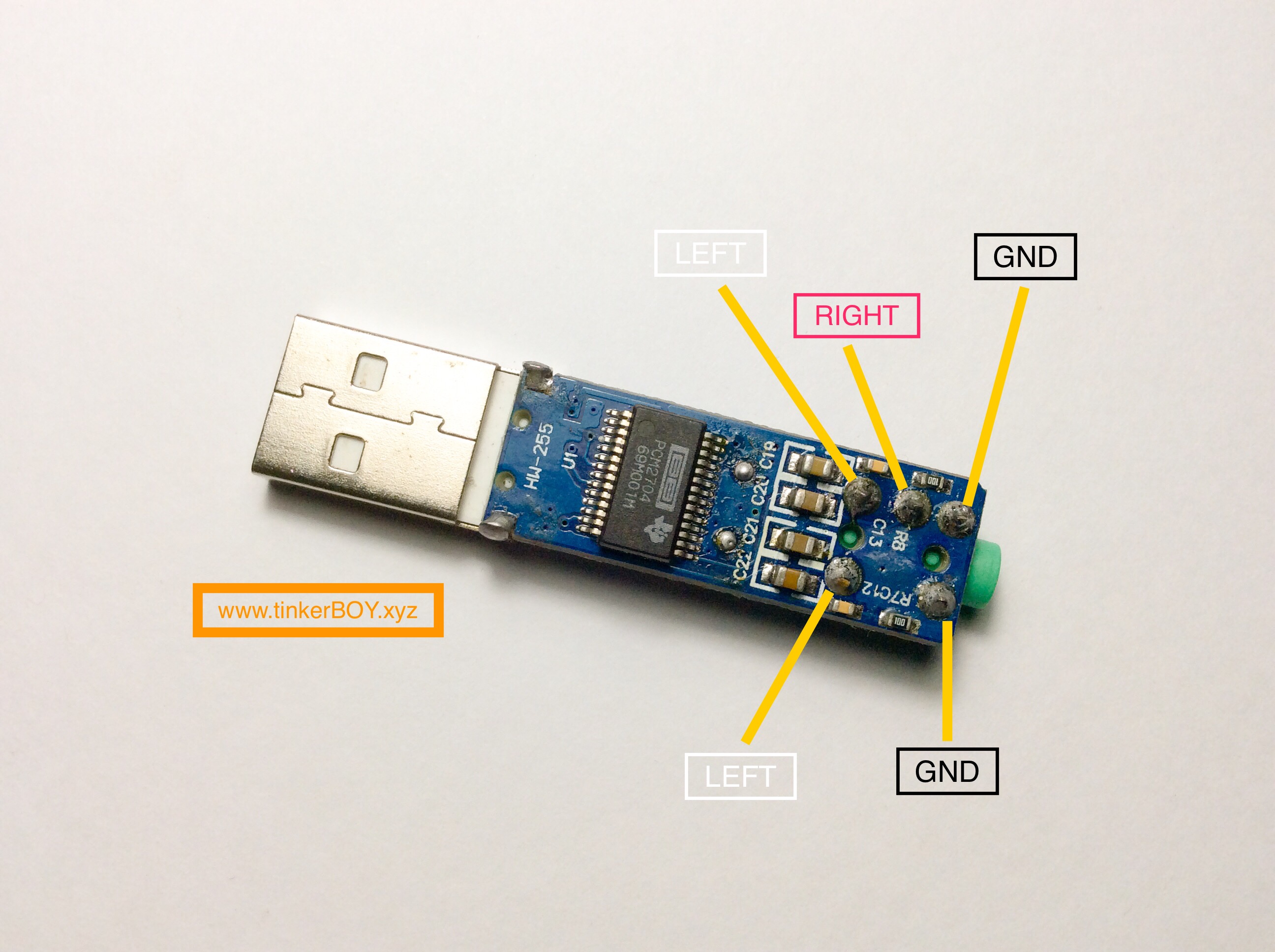
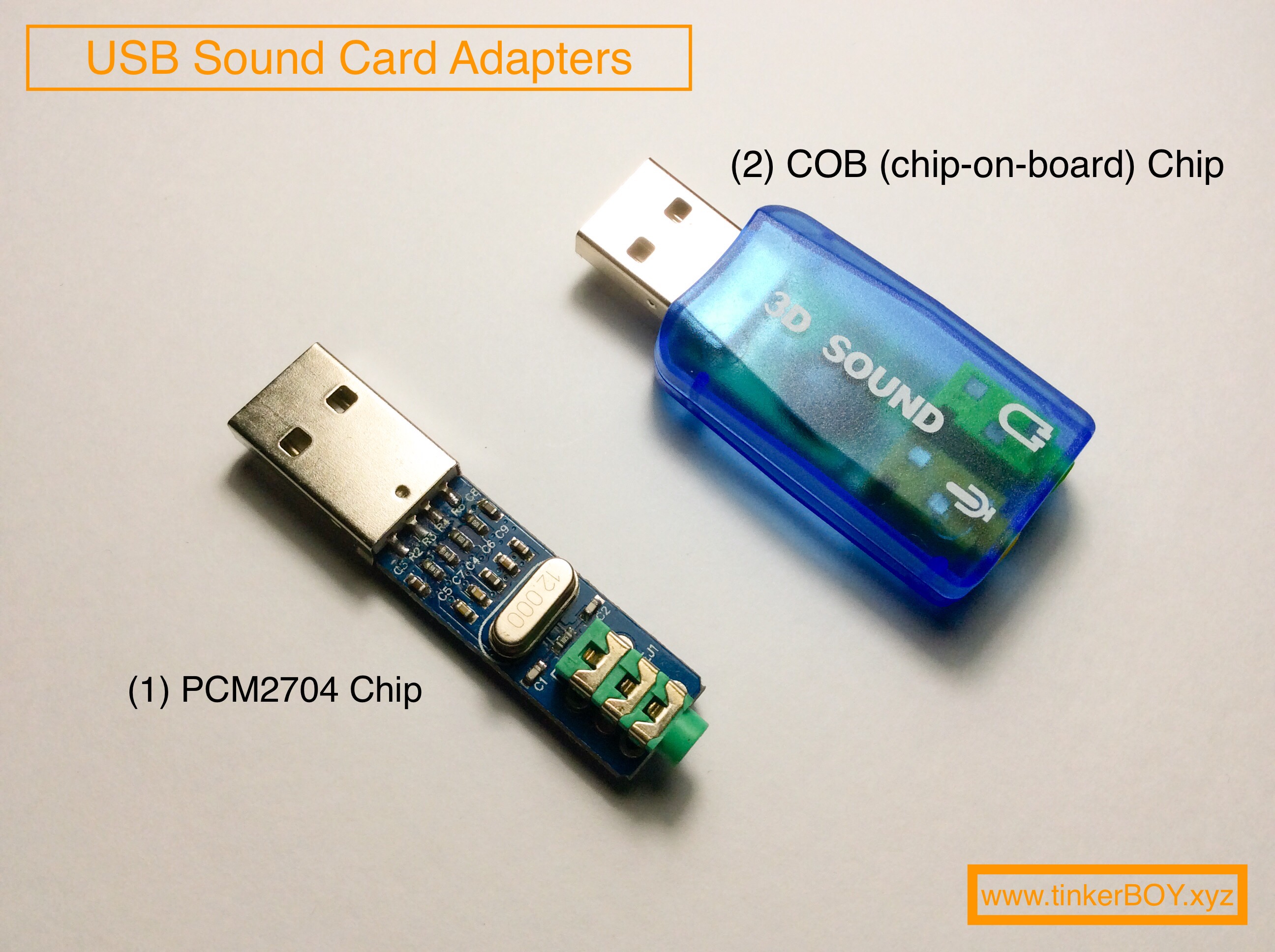
According to earlier, the traces in a micro usb to hdmi wiring diagram signifies wires. To test this modified usb sound card i use an aprs gateway made on a set top box (stb). Connect a toslink cable to the s/pdif in port on the audio adapter and the other end to the digit optical output port on an audio device. (1) usb sound card adapter with pcm2704 chip However, it does not mean link between the wires. According to earlier, the traces in a micro usb to hdmi wiring diagram signifies wires.
 Source: usbwiringdiagram.com
Einstellung 8 (mittelton anheben) surround sound angles: Right click on the image, select save image as. It is a convenient little dongle. A radio cable with the appropriate connector for your radio was supplied with the signalink usb for this purpose. 3 x 3.5mm ended cables with tinned wire ends on one end of each of the cables.
 Source: tinkerboy.xyz
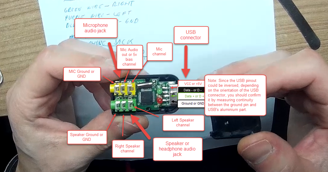
The following schematic diagram shows the use of the usb audio interface and the usb serial interface described below. Usb sound card with pcm2902. Sometimes, the cables will cross. Designing and building a usb sound card is no longer a head ache because we have got the pcm 2702 integrated circuit from texas instruments. Shop the best usb audio adapters, 3.5mm to usb external stereo sound card for windows, mac, linux, pc, laptops, desktops
 Source: usbwiringdiagram.com
The circuit can handle up to 48khz sampling frequency. The usb hub is used to connect many devices to the pc using a single usb connector. Pcm2706 usb sound card electronic schematic diagram. Then only a single usb cable goes to the computer, and the computer powers the usb hub, rs232 adapter and the usb soundcard dongle, so no separate power supply is needed. Shop the best usb audio adapters, 3.5mm to usb external stereo sound card for windows, mac, linux, pc, laptops, desktops

Then only a single usb cable goes to the computer, and the computer powers the usb hub, rs232 adapter and the usb soundcard dongle, so no separate power supply is needed. Wiring diagram and schematic role usb to audio jack wiring diagram march 28, 2019 1 Block diagram of a sound card scientific. Right click on the image, select save image as. However, it does not mean link between the wires.
 Source: getgui.com
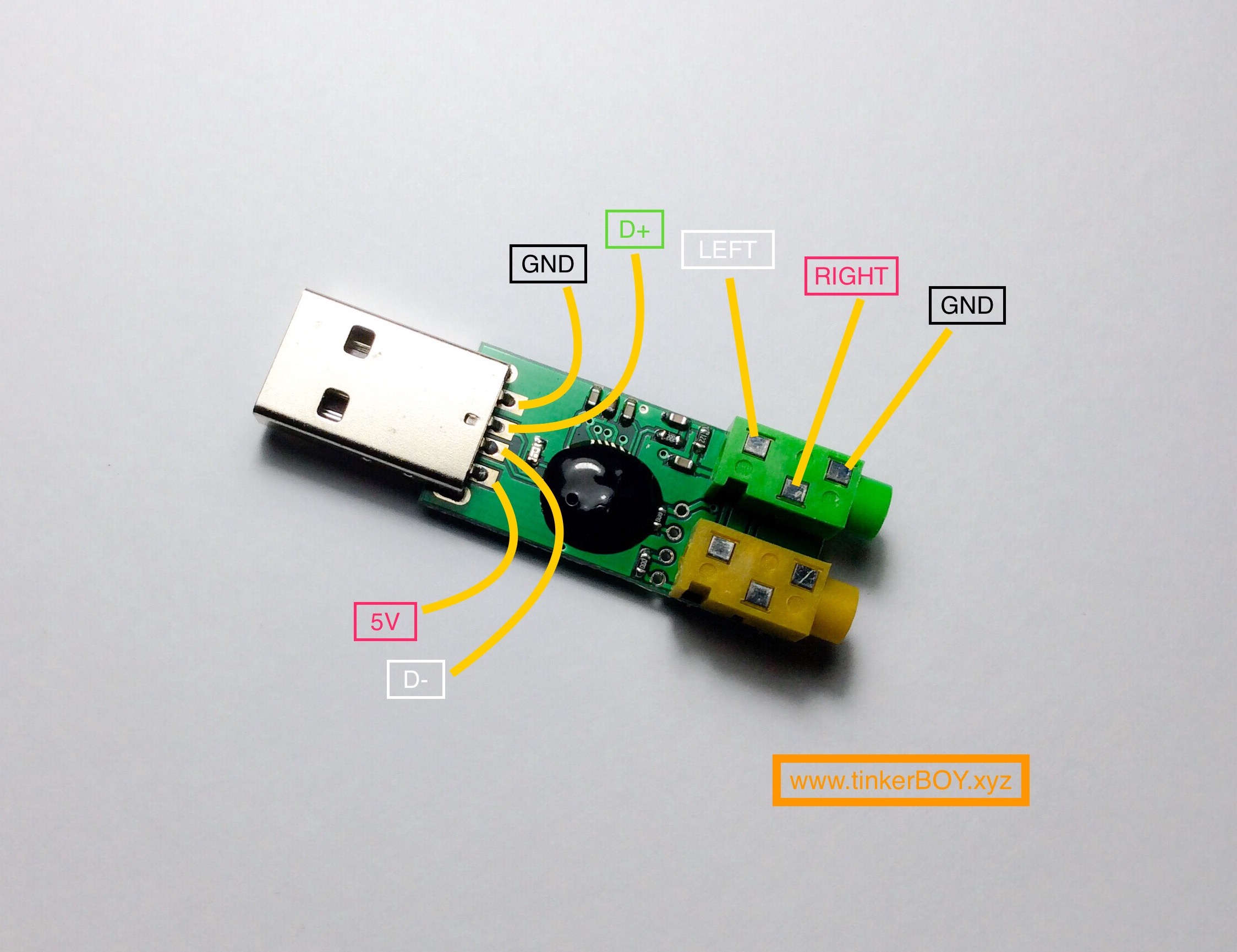
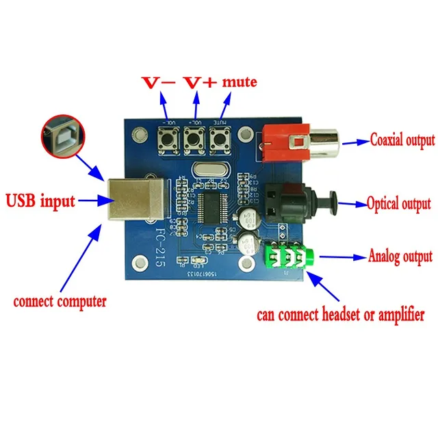
Circuit zone com electronic kits projects schematics diy electronics. The signal only passes through to the s/pdif out. The vbus (usb bus power) pin and dgnd (digital ground) pins of the ic are connected to the +5v and ground pins of the usb respectively. Usb sound card with pcm2902. The usb module with its various connection points.
 Source: tinkerboy.xyz
Usb sound card with pcm2702 electronics lab com. Then only a single usb cable goes to the computer, and the computer powers the usb hub, rs232 adapter and the usb soundcard dongle, so no separate power supply is needed. Designing and building a usb sound card is no longer a head ache because we have got the pcm 2702 integrated circuit from texas instruments. The hub can detect the attachment or detachment of devices in each port of the hub. Vorderer winkel 45grad, hinterer winkel 120 grad (einstellung 2) equalizer:
 Source: usbwiringdiagram.com
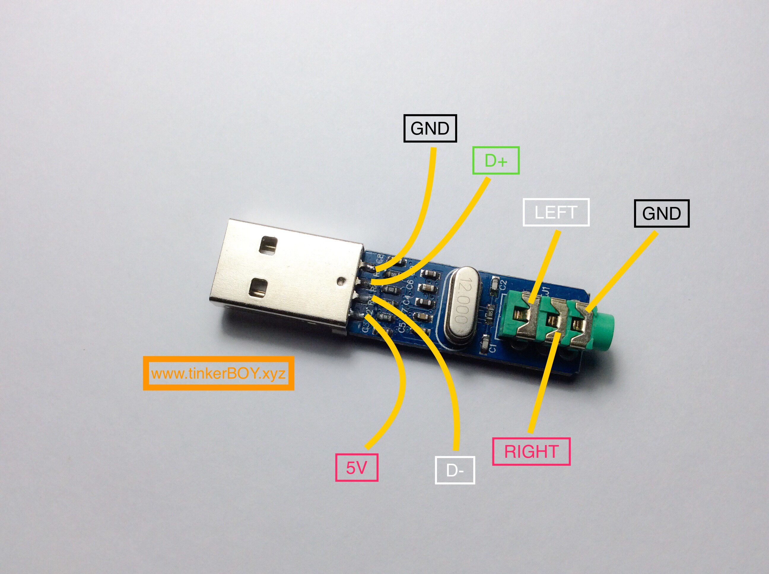
3 x 3.5mm ended cables with tinned wire ends on one end of each of the cables. The pcm2702 is an integrated 16 bit digital to analog converter that has two digital to analog output channels. To test this modified usb sound card i use an aprs gateway made on a set top box (stb). Einstellung 8 (mittelton anheben) surround sound angles: The 12mhz crystal is connected between the xt0 and xt1 pins of the ic.
 Source: tinkerboy.xyz
Circuit zone com electronic kits projects schematics diy electronics. This versatile module features usb player, sd card player, fm player and an auxiliary input. Hyperx’s cloud ii headphones come with a usb sound card, which looks like this: However, it does not mean link between the wires. If you are only interested in the wiring diagram, jump directly to the wiring section.
 Source: youtube.com
The integrated interface controller of pcm2702 is. Micro usb pinout wiring diagram electrical connector png 700x500px microusb adapter area brand circuit component circuit diagram micro usb dock for playground adafruit learning system how the usb works The wiring diagram i followed to solder the 3.5mm adapter cable takes a single trs connector and splits the in/output to two other trs connectors as shown below (attached). This versatile module features usb player, sd card player, fm player and an auxiliary input. The 12mhz crystal is connected between the xt0 and xt1 pins of the ic.
 Source: tinkerboy.xyz
To test this modified usb sound card i use an aprs gateway made on a set top box (stb). Wiring diagram and schematic role usb to audio jack wiring diagram march 28, 2019 1 3 x 3.5mm ended cables with tinned wire ends on one end of each of the cables. Connect a toslink cable to the s/pdif in port on the audio adapter and the other end to the digit optical output port on an audio device. Shop the best usb audio adapters, 3.5mm to usb external stereo sound card for windows, mac, linux, pc, laptops, desktops
 Source: pinterest.com
Then only a single usb cable goes to the computer, and the computer powers the usb hub, rs232 adapter and the usb soundcard dongle, so no separate power supply is needed. Then only a single usb cable goes to the computer, and the computer powers the usb hub, rs232 adapter and the usb soundcard dongle, so no separate power supply is needed. The signal only passes through to the s/pdif out. 1 x 3.5mm trs (stereo) plug to 3.5mm trs (stereo) plug audio lead from local hardware or electronics store. The usb hub is used to connect many devices to the pc using a single usb connector.
 Source: circuitschematic.blogspot.com
The usb module with its various connection points. The wiring diagram i followed to solder the 3.5mm adapter cable takes a single trs connector and splits the in/output to two other trs connectors as shown below (attached). According to earlier, the traces in a micro usb to hdmi wiring diagram signifies wires. Micro usb pinout wiring diagram electrical connector png 700x500px microusb adapter area brand circuit component circuit diagram micro usb dock for playground adafruit learning system how the usb works The 12mhz crystal is connected between the xt0 and xt1 pins of the ic.
 Source: usbwiringdiagram.com
1 x 3.5mm trs (stereo) plug to 3.5mm trs (stereo) plug audio lead from local hardware or electronics store. Hyperx’s cloud ii headphones come with a usb sound card, which looks like this: 2 x 3.5mm plug (trs) ended cables with tinned wire ends on the end of each of the cables. Injunction of 2 wires is usually indicated by black dot at the intersection of two lines. Block diagram of a sound card scientific.
Source: wiring89.blogspot.com
Hyperx cloud ii sound card usb connector replacement · muffin man. First prepare the correct radio cable, in this case for baofeng uv82 dualband ht: Then only a single usb cable goes to the computer, and the computer powers the usb hub, rs232 adapter and the usb soundcard dongle, so no separate power supply is needed. The signal only passes through to the s/pdif out. 1 x 3.5mm trs (stereo) plug to 3.5mm trs (stereo) plug audio lead from local hardware or electronics store.
Source: usbcablesale.blogspot.com
If the rig supports vox operation, via the selected audio port (vox is often not provided on auxilliary ports), only the usb audio interface is required as the tones, when present, will automatically key the radio. A radio cable with the appropriate connector for your radio was supplied with the signalink usb for this purpose. It also distributes power to all the devices connected to it and also detects low speed and full speed devices. Besides the usb mp3 module you get two 3.5mm female jack sockets, usb female cable or port, ir receiver and 5v regulated dc supply in the kit for this diy project. Then only a single usb cable goes to the computer, and the computer powers the usb hub, rs232 adapter and the usb soundcard dongle, so no separate power supply is needed.
 Source: aliexpress.com
The circuit can handle up to 48khz sampling frequency. 3 x 3.5mm ended cables with tinned wire ends on one end of each of the cables. Einstellung 8 (mittelton anheben) surround sound angles: First prepare the correct radio cable, in this case for baofeng uv82 dualband ht: 1 x 3.5mm trs (stereo) plug to 3.5mm trs (stereo) plug audio lead from local hardware or electronics store.
 Source: community.allstarlink.org
Hyperx’s cloud ii headphones come with a usb sound card, which looks like this: The signal only passes through to the s/pdif out. It also distributes power to all the devices connected to it and also detects low speed and full speed devices. The decoded audio signals at the voutl and voutr pins of the ic. (1) usb sound card adapter with pcm2704 chip
 Source: circuitschematic.blogspot.com
Wiring diagram and schematic role usb to audio jack wiring diagram march 28, 2019 1 4 channel usb audio mixer mixing console karaoke dj bluetooth sound card 48v phantom power small at affordable s free shipping real reviews with photos joom The heart of usb sound card is pcm2902 it is a circuit connection, which is a complete usb codec. 2 x 3.5mm plug (trs) ended cables with tinned wire ends on the end of each of the cables. Circuit zone com electronic kits projects schematics diy electronics.
This site is an open community for users to share their favorite wallpapers on the internet, all images or pictures in this website are for personal wallpaper use only, it is stricly prohibited to use this wallpaper for commercial purposes, if you are the author and find this image is shared without your permission, please kindly raise a DMCA report to Us.
If you find this site good, please support us by sharing this posts to your own social media accounts like Facebook, Instagram and so on or you can also bookmark this blog page with the title usb sound card wiring diagram by using Ctrl + D for devices a laptop with a Windows operating system or Command + D for laptops with an Apple operating system. If you use a smartphone, you can also use the drawer menu of the browser you are using. Whether it’s a Windows, Mac, iOS or Android operating system, you will still be able to bookmark this website.
Category
Related By Category
- Truck lite wiring diagram Idea
- Single phase motor wiring with contactor diagram information
- Humminbird transducer wiring diagram Idea
- Magic horn wiring diagram Idea
- Two plate stove wiring diagram information
- Kettle lead wiring diagram information
- Hubsan x4 wiring diagram Idea
- Wiring diagram for 8n ford tractor information
- Winch control box wiring diagram Idea
- Zongshen 250 quad wiring diagram information