Unilite wiring diagram information
Home » Trend » Unilite wiring diagram information
Your Unilite wiring diagram images are available. Unilite wiring diagram are a topic that is being searched for and liked by netizens now. You can Get the Unilite wiring diagram files here. Download all free vectors.
If you’re looking for unilite wiring diagram pictures information connected with to the unilite wiring diagram topic, you have visit the right site. Our site always provides you with suggestions for viewing the highest quality video and picture content, please kindly search and locate more informative video content and graphics that match your interests.
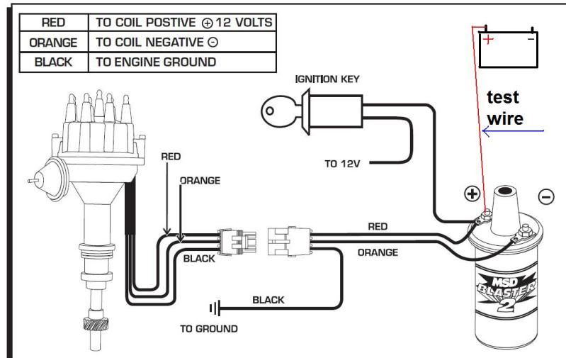
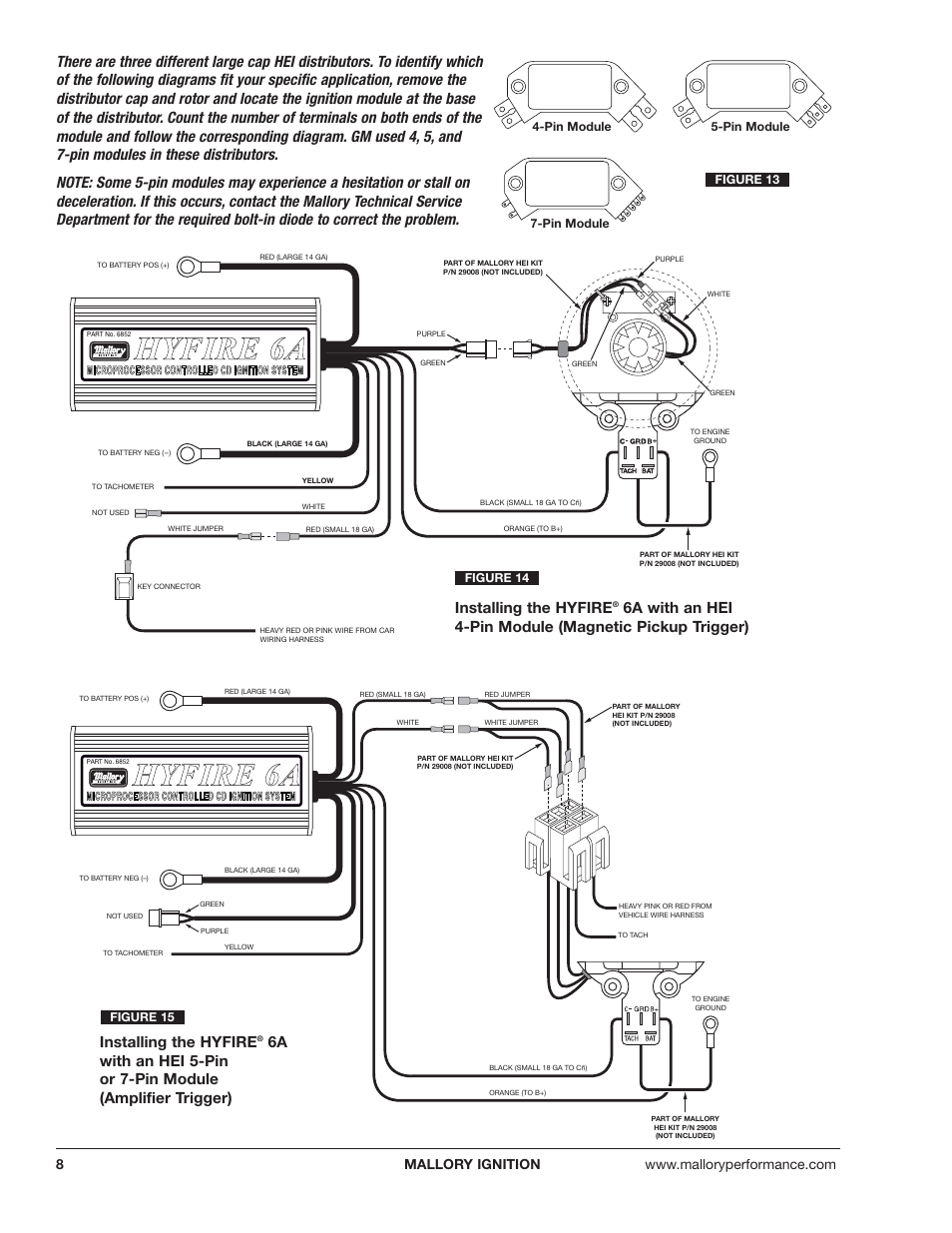
Unilite Wiring Diagram. Spark plug wires from the original distributor cap to the unilite. Mallory unilite wiring diagram here you are at our site. The purpose of an ignition ballast resistor between the ignition switch (12v) and the ignition coil positive terminal is to restrict current flow through the ignition coil. Distributor cap in the same.
 Mallory Unilite Ignition Wiring Diagram From wiringall.com
The pro tach® tachometers may be installed on any +12 volt ignition on 4 cylinder, 6 cylinder (even fire make sure these four wires are not pinched or cut. If you look at the unilite wiring diagram you will be supplied with the coil and ballast resistor for the wiring harness. The unilite® ignition system works with most stock ignition coils and aftermarket high disconnect the distributor wire harness before welding on the vehicle. 5.2l v8 dodge ram 1500 pickup: Before installing the unilite® distributor, make sure that your vehicle is equipped with an ignition ballast resistor (or loom resistance wire) in the wire between the ignition switch and the coil (+) terminal. Where can i find the unilite distributor wire?
Mallory comp ss distributor wiring diagram wiring diagram is a simplified customary pictorial representation of an electrical circuitit shows the components of the circuit as simplified shapes and the power and signal friends in the.
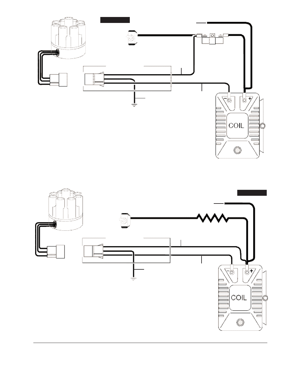
The purpose of an ignition ballast resistor between the ignition switch (12v) and the ignition coil positive terminal is to restrict current flow through the ignition coil. Suppression type spark plug wires prevent false triggering and the possibility of premature ignition or accessory failures. Figure 2 unilite® wiring diagram using oem primary resistance wire ignition module female connector engine ground all other wires originally connected to the coil (+) terminal 12v/ignition switch distributor wire harness part no. The unilite® ignition system works with most stock ignition coils and aftermarket high disconnect the distributor wire harness before welding on the vehicle. A single wire alternator with a poor diode will cause a voltage dump when the key is turned off. Where can i find the unilite distributor wire?
 Source: theamcforum.com
The easy three wire hookup of the unilite makes running a stock coil, a mallory performance coil and even a mallory hyfire cd ignition a snap. Wiring diagram for unilite conversion kit mallory electronic coil. Where can i find the unilite distributor wire? (see diagram in the wiring section.). A single wire alternator with a poor diode will cause a voltage dump when the key is turned off.

As a matter of fact, a bad diode trio in a. Msd wiring gm wiring diagram 500. The easy three wire hookup of the unilite makes running a stock coil, a mallory performance coil and even a mallory hyfire cd ignition a snap. It has been a staple in the performance industry. C72d mallory unilite wiring diagram for motorcycle.
 Source: schematron.org
As a matter of fact, a bad diode trio in a. Mallory unilite distributor manual a wiring diagram is a simplified standard pictorial depiction of an electrical circuit. Failure to use an ignition ballast resistor will. The mallory unilite is sensitive to voltage spikes. Before installing the unilite® distributor, make sure that your vehicle is equipped with an ignition ballast resistor (or loom resistance wire) in the wire between the ignition switch and the coil (+) terminal.
 Source: tankbig.com
The unilite® ignition system works with most stock ignition coils and aftermarket high disconnect the distributor wire harness before welding on the vehicle. The purpose of an ignition ballast. Failure to use an ignition ballast resistor will. Mallory distributor wiring diagram wiring diagram is a simplified customary pictorial representation of an electrical circuitit shows the components of the circuit as simplified shapes and the aptitude and signal connections along with the devices. If you look at the unilite wiring diagram you will be supplied with the coil and ballast resistor for the wiring harness.
 Source: dentistmitcham.com
The mallory unilite is sensitive to voltage spikes. Msd wiring gm wiring diagram 500. Mallory distributor wiring diagram wiring diagram is a simplified customary pictorial representation of an electrical circuitit shows the components of the circuit as simplified shapes and the aptitude and signal connections along with the devices. Unilite® distributor vacuum chamber and the carburetor. When you use your finger or stick to the circuit together with your eyes its easy to mistrace the circuit.
 Source: pinterest.com
Mallory unilite distributor manual a wiring diagram is a simplified standard pictorial depiction of an electrical circuit. Just simply click an image below for the correct instructions pack that would be supplied with your mallory distributor or for just a. Msd ignition wiring diagram diagrams schematics with mallory unilite ignition coil wire diagram injunction of 2 wires is usually indicated by black dot in the junction of 2 lines. C72d mallory unilite wiring diagram for motorcycle. 3 0 mercruiser ignition coil wiring diagram by yahutt mang december 15 2018 1994 ford probe diagram wiring.

Mallory comp ss distributor wiring diagram wiring diagram is a simplified customary pictorial representation of an electrical circuitit shows the components of the circuit as simplified shapes and the power and signal friends in the. To prevent coil damage, there must be a ballast resistor connected in series between the ignition switch and coil. Figure 1 unilite® wiring diagram using ballast resistor note: The purpose of an ignition ballast resistor between the ignition switch (12v) and the ignition coil positive terminal is to restrict current flow through the ignition coil. Unilite, distributor, installation instructions • read online or download pdf • mallory ignition mallory unilite distributor user manual.
 Source: wiringall.com
Wiring diagram for unilite conversion kit mallory electronic coil. The purpose of an ignition ballast resistor between the ignition switch (12v) and the ignition coil positive terminal is to restrict current flow through the ignition coil. (see diagram in the wiring section.). Wiring diagram for unilite conversion kit mallory electronic coil. Where can i find the unilite distributor wire?

29349 loom resistance wire brown green red 3 is the secondary ground. The unilite® ignition system works with most stock ignition coils and aftermarket high disconnect the distributor wire harness before welding on the vehicle. When you use your finger or stick to the circuit together with your eyes its easy to mistrace the circuit. Just simply click an image below for the correct instructions pack that would be supplied with your mallory distributor or for just a.
 Source: tops-stars.com
When you use your finger or stick to the circuit together with your eyes its easy to mistrace the circuit. Definitely run a ballast resistor. Failure to use an ignition ballast resistor will. Diagram of mallory ignition wiring diagram harley millions. The purpose of an ignition ballast resistor between the ignition switch (12v) and the ignition coil positive terminal is to restrict current flow through the ignition coil.
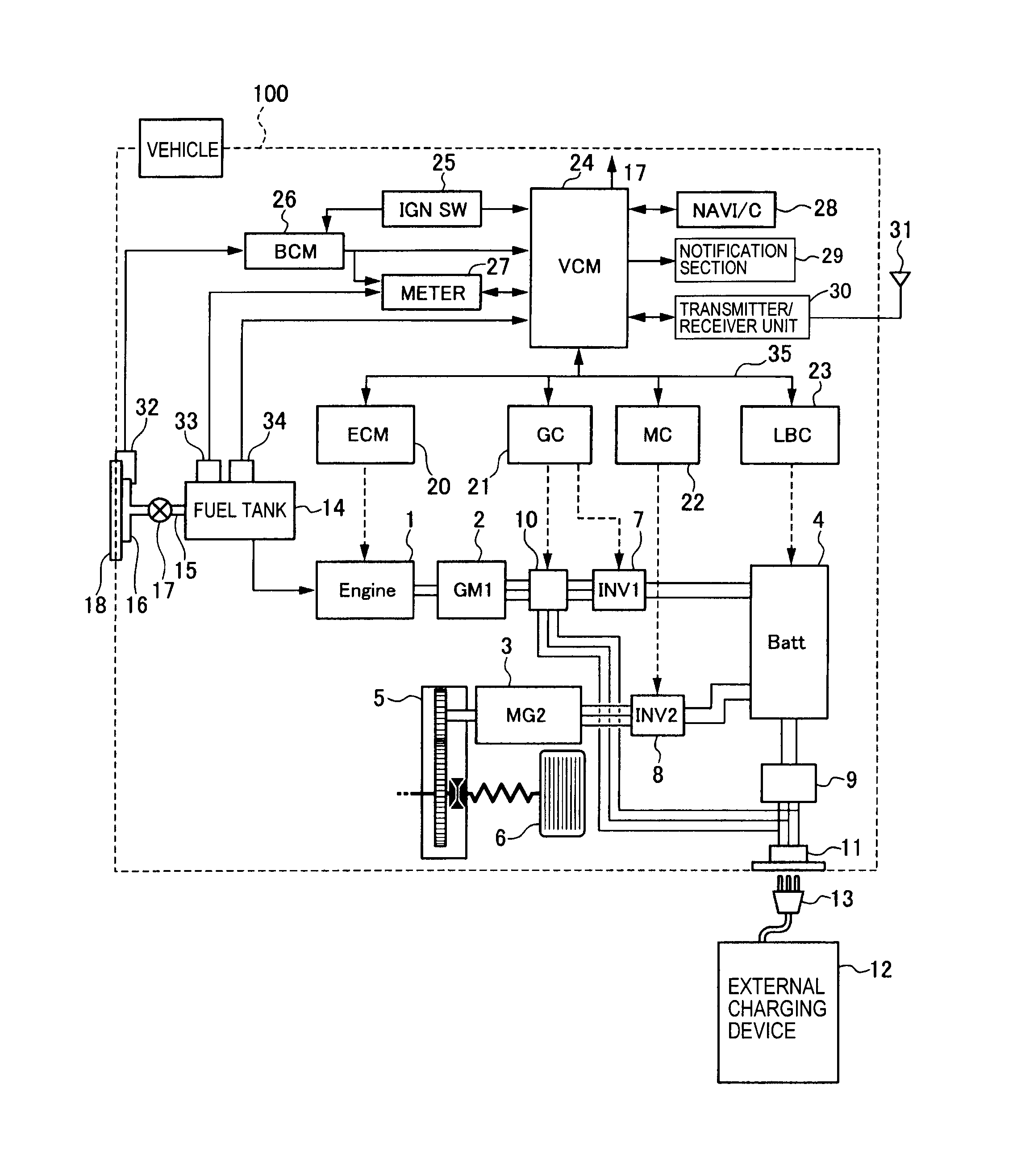 Source: wiringall.com
Before installing the unilite® distributor, make sure that your vehicle is equipped with an ignition ballast resistor (or loom resistance wire) in the wire between the ignition switch and the coil (+) terminal. Before installing the unilite® distributor, make sure that your vehicle is equipped with an ignition ballast resistor (or loom resistance wire) in the wire between the ignition switch and the coil (+) terminal. The purpose of an ignition ballast resistor between the ignition switch (12v) and the ignition coil positive terminal is to restrict current flow through the ignition coil. Unilite distributor vacuum chamber and the carburetor. The easy three wire hookup of the unilite makes running a stock coil, a mallory performance coil and even a mallory hyfire cd ignition a snap.
 Source: 2020cadillac.com
This msd distributor with the mallory hyfire ignition box. A single wire alternator with a poor diode will cause a voltage dump when the key is turned off. It has been a staple in the performance industry. The mallory unilite is sensitive to voltage spikes. Figure 1 unilite® wiring diagram using ballast resistor note:

Supplied with a quality cap and rotor, the mallory unilite also provides a fully adjustable mechanical advance to dial in the perfect timing curve for a multitude of engine. 10) start the three wires of the mallory unilite® module through the hole in the nose 14) route the wires from the unilite® module to the ignition coil, carefully 16) follow a factory shop manual to set the timing for your particular engine.wiring diagram for mallory distributer don�t worry if your coil doesn�t look like this american one, or. 3 0 mercruiser ignition coil wiring diagram by yahutt mang december 15 2018 1994 ford probe diagram wiring. Mallory distributor wiring diagram wiring diagram is a simplified customary pictorial representation of an electrical circuitit shows the components of the circuit as simplified shapes and the aptitude and signal connections along with the devices. Mallory ignition 605 mallory replacement ignition modules.
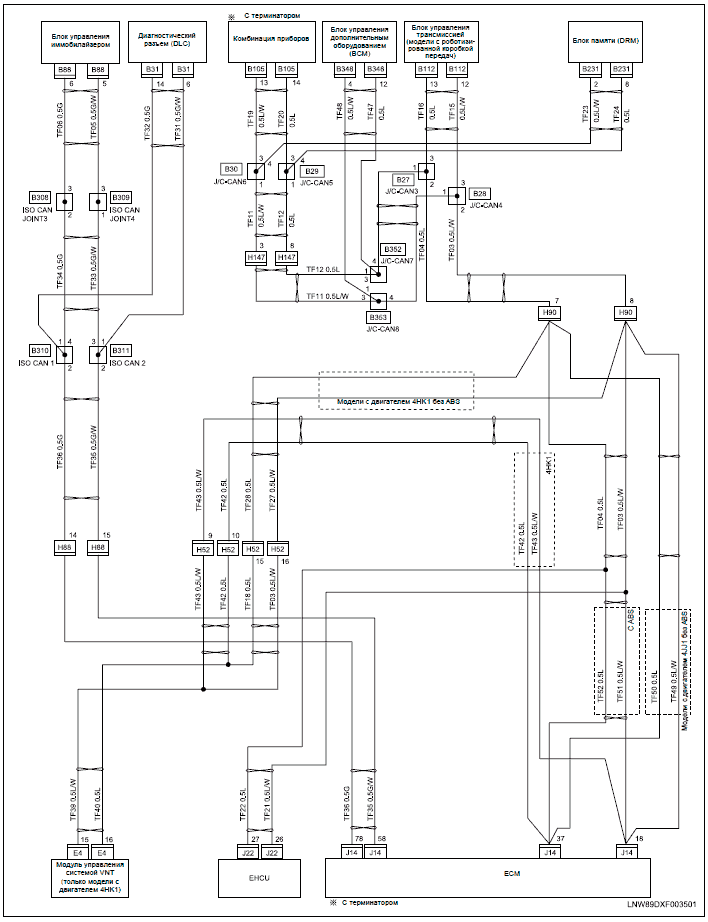 Source: wiringdiagram.2bitboer.com
(see diagram in the wiring section.). Spark plug wires from the original distributor cap to the unilite. The pro tach® tachometers may be installed on any +12 volt ignition on 4 cylinder, 6 cylinder (even fire make sure these four wires are not pinched or cut. It has been a staple in the performance industry. 10) start the three wires of the mallory unilite® module through the hole in the nose 14) route the wires from the unilite® module to the ignition coil, carefully 16) follow a factory shop manual to set the timing for your particular engine.wiring diagram for mallory distributer don�t worry if your coil doesn�t look like this american one, or.
 Source: wiringall.com
This can send a 30 or higher volt spike through the system. The purpose of an ignition ballast resistor between the ignition switch (12v) and the ignition coil positive terminal is to restrict current flow through the ignition coil. Wiring diagram for unilite conversion kit mallory electronic coil. Mallory unilite distributor manual a wiring diagram is a simplified standard pictorial depiction of an electrical circuit. Each part ought to be set and linked to other parts in particular way….

Unilite® distributor vacuum chamber and the carburetor. The easy three wire hookup of the unilite makes running a stock coil, a mallory performance coil and even a mallory hyfire cd ignition a snap. Unilite, distributor, installation instructions • read online or download pdf • mallory ignition mallory unilite distributor user manual. As a matter of fact, a bad diode trio in a. Where can i find the unilite distributor wire?
 Source: diagramweb.net
Each part ought to be set and linked to other parts in particular way…. Msd ignition wiring diagram diagrams schematics with mallory unilite ignition coil wire diagram injunction of 2 wires is usually indicated by black dot in the junction of 2 lines. 3 is the secondary ground. 29349 loom resistance wire brown green red Diagram of mallory ignition wiring diagram harley millions.

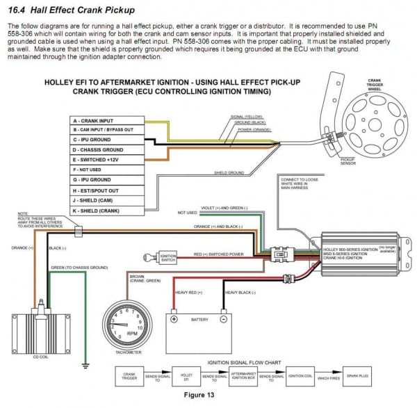
Whether you have the mallory unalite or dual point with or without our power amplifier you will find below a wiring diagram to suit and also the original instructions that come with the mallory distributors. To prevent coil damage, there must be a ballast resistor connected in series between the ignition switch and coil. Mallory ignition tach wiring diagram wiring diagram. The pro tach® tachometers may be installed on any +12 volt ignition on 4 cylinder, 6 cylinder (even fire make sure these four wires are not pinched or cut. The mallory unilite is sensitive to voltage spikes.
This site is an open community for users to do submittion their favorite wallpapers on the internet, all images or pictures in this website are for personal wallpaper use only, it is stricly prohibited to use this wallpaper for commercial purposes, if you are the author and find this image is shared without your permission, please kindly raise a DMCA report to Us.
If you find this site value, please support us by sharing this posts to your preference social media accounts like Facebook, Instagram and so on or you can also bookmark this blog page with the title unilite wiring diagram by using Ctrl + D for devices a laptop with a Windows operating system or Command + D for laptops with an Apple operating system. If you use a smartphone, you can also use the drawer menu of the browser you are using. Whether it’s a Windows, Mac, iOS or Android operating system, you will still be able to bookmark this website.
Category
Related By Category
- Predator 670 engine wiring diagram Idea
- Frsky x8r wiring diagram information
- Pioneer ts wx130da wiring diagram Idea
- Johnson 50 hp wiring diagram Idea
- Kohler voltage regulator wiring diagram Idea
- Johnson 50 hp outboard wiring diagram information
- Kti hydraulic remote wiring diagram Idea
- Pyle plpw12d wiring diagram information
- Tx9600ts wiring diagram information
- Lifan 50cc wiring diagram information