Two wire pressure transmitter wiring diagram information
Home » Trending » Two wire pressure transmitter wiring diagram information
Your Two wire pressure transmitter wiring diagram images are available. Two wire pressure transmitter wiring diagram are a topic that is being searched for and liked by netizens now. You can Download the Two wire pressure transmitter wiring diagram files here. Find and Download all royalty-free images.
If you’re searching for two wire pressure transmitter wiring diagram pictures information connected with to the two wire pressure transmitter wiring diagram topic, you have come to the right site. Our website always gives you hints for seeing the highest quality video and image content, please kindly search and locate more informative video content and graphics that match your interests.
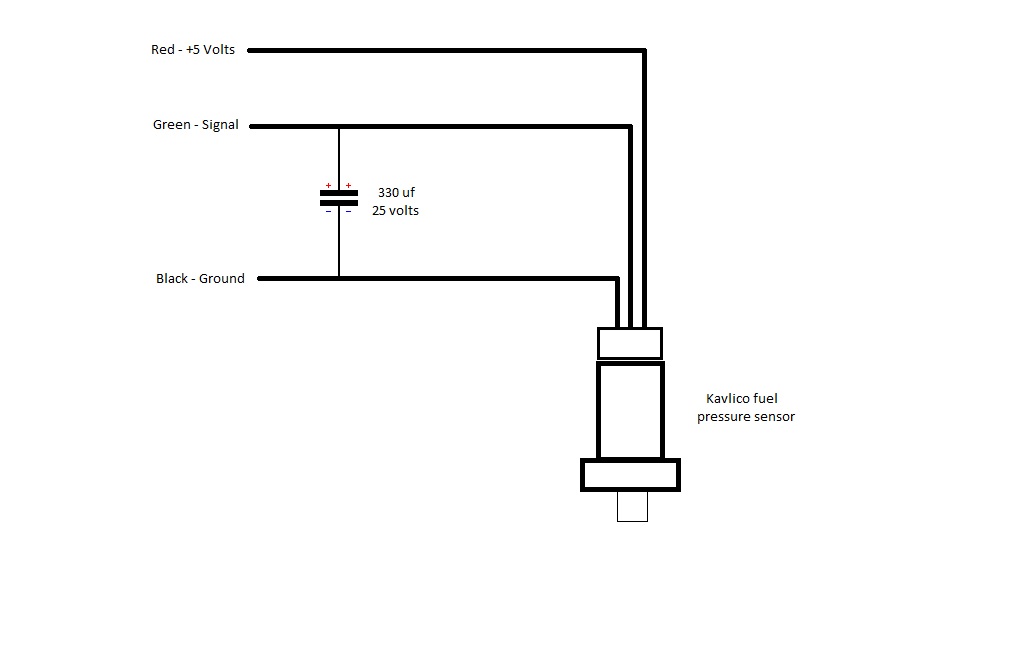
Two Wire Pressure Transmitter Wiring Diagram. The power supply and the instruments are usually mounted in the control room. Yes a 3 wire tx will work, you need to determine a common connection between the 5vdc supply and the digital meter. Next is a resonance stage and the final stage built with a minimum 1w transistor which must have a heatsink. Place taps to the side of the line.
 Pressure Transducer Wiring Diagram PURPLEITUUNGGU From purple-itu-unggu.blogspot.com
A wiring diagram is a simplified standard photographic representation of an. 2 wire pressure transmitter wiring diagram. 3 wire pressure transmitter wiring diagram. 2 wire transmitter wiring diagram. Two wire pressure transmitter wiring diagram posted by margaret byrd posted on september 3 2021. Place taps in the top or side of the line.
It features a very good accuracy, a robust design and an exceptional number of variants, meaning it can be suited to the widest.
1,910 74 variety of wire crafts. Mount beside or below the taps. Several transmitter wiring options exist. Process connection g ¼ a din e, ¼ npt and others. These connection methods are of great concern to the instrument engineer technician. All connectors with.the model s pressure transmitter for general industrial applications is the ideal solution for customers with demanding measuring requirements.
 Source: wholefoodsonabudget.com
A transducer produces millivolts, amplified voltage, or current output. It reveals the parts of the circuit as. A transducer produces millivolts, amplified voltage, or current output. Several transmitter wiring options exist. These connection methods are of great concern to the instrument engineer technician.
 Source: wiring121.blogspot.com
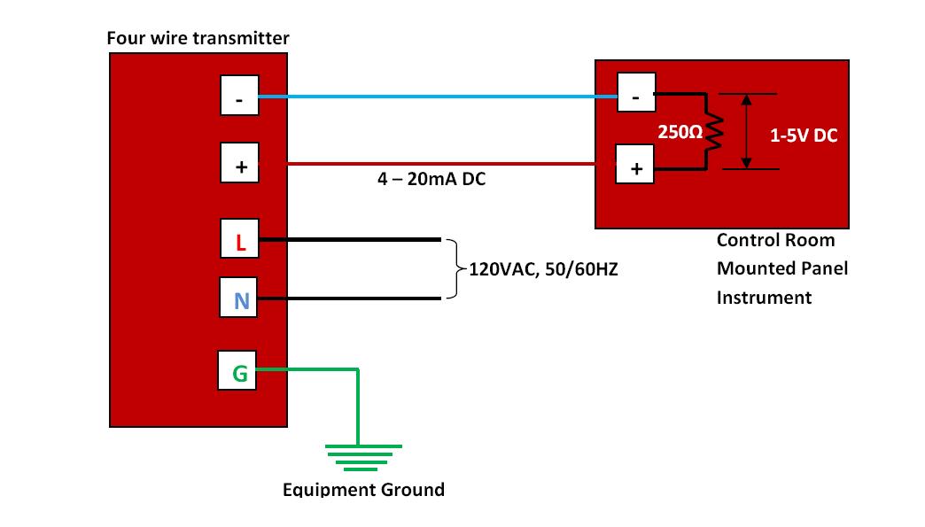
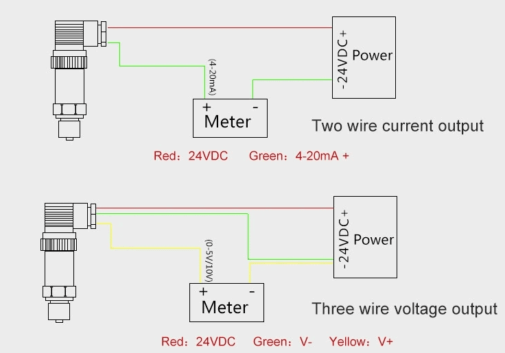
All connectors with.the model s pressure transmitter for general industrial applications is the ideal solution for customers with demanding measuring requirements. A 4 wire transmitter has 2 wires connected to a power supply and 2 signal wires connected to the plc. This is one of the simplest wiring types as it only has two wires. All connectors with.the model s pressure transmitter for general industrial applications is the ideal solution for customers with demanding measuring requirements. Pressure transmitter calibration transmitter analog circuits how to apply today s electronic process transmitters pressure temperature flow and level are connected in different wire types or configurations.
 Source: wholefoodsonabudget.com
Assortment of 2 wire pressure transducer wiring diagram. Two wire pressure transmitter wiring diagram posted by margaret byrd posted on september 3 2021. 2 wire pressure transmitter wiring diagram. Yes a 3 wire tx will work, you need to determine a common connection between the 5vdc supply and the digital meter. Mount beside or below the taps.
 Source: ricardolevinsmorales.com
Pressure transmitter calibration transmitter analog circuits how to apply today s electronic process transmitters pressure temperature flow and level are connected in different wire types or configurations. Two wire pressure transmitter wiring diagram. It features a very good accuracy, a robust design and an exceptional number of variants, meaning it can be suited to the widest. You may like these posts. Mount beside or below the taps.
 Source: instrumentationtoolbox.com
Either the transmitter or the receiver would provide the power supply to the loop. The left side is labeled “t” and refers to “transmitter”. Process connection g ¼ a din e, ¼ npt and others. You may like these posts. A thermistor is a resistor that is more sensitive to temperature changes than a standard resistor.
 Source: instrumentationtoolbox.com
A thermistor is a resistor that is more sensitive to temperature changes than a standard resistor. 2 wire pressure transmitter wiring diagram. The left side is labeled “t” and refers to “transmitter”. Typical wiring configurations are shown in figure 2. Mount beside or above the taps.
 Source: ricardolevinsmorales.com
A wiring diagram is a simplified standard photographic. You may like these posts. 1,910 74 variety of wire crafts. A wiring diagram is a simplified standard photographic representation of an. 2 wire pressure transmitter wiring diagram rf capacitance level transmitter marktechnical nl vp8 series beginner s guide to differential pressure transmitters troubleshooting current loops understanding analog 4 to 20 ma current loop output signal facebook;
 Source: electronics.stackexchange.com
However, a separate power supply is also available as an option. Two wire pressure transmitter wiring diagram posted by margaret byrd posted on september 3 2021. Industrial transmitters are available for monitoring many parameters these including pressure, temperature and flow etc. 3 wire pressure transmitter wiring diagram. It reveals the parts of the circuit as.
 Source: purple-itu-unggu.blogspot.com
The wire pair colors are blue orange green and brown. A 2 wire transmitter has only 2 wires and is connected in series with the power supply and the plc. 2 wire transmitter wiring diagram. A transducer produces millivolts, amplified voltage, or current output. May 2 2018 by headcontrolsystem.
Source: drivenheisenberg.blogspot.com
These connection methods are of great concern to the instrument engineer technician. Either the transmitter or the receiver would provide the power supply to the loop. The base of the triangle is labeled “r” and refers to “receiver”. It features a very good accuracy, a robust design and an exceptional number of variants, meaning it can be suited to the widest. The wire pair colors are blue orange green and brown.
Source: strawberry-sweet.blogspot.com
It reveals the parts of the circuit as. The left side is labeled “t” and refers to “transmitter”. Place taps to the side of the line. Pressure transmitter calibration transmitter analog circuits how to apply today s electronic process transmitters pressure temperature flow and level are connected in different wire types or configurations. Place taps in the top or side of the line.
 Source: hestiahelper.blogspot.com
A wiring diagram is a simplified standard photographic. All connectors with.the model s pressure transmitter for general industrial applications is the ideal solution for customers with demanding measuring requirements. Either the transmitter or the receiver would provide the power supply to the loop. These connection methods are of great concern to the instrument engineer technician. It reveals the parts of the circuit as streamlined shapes and the power as well as signal connections in between the gadgets.
 Source: wiringdiagram81.blogspot.com
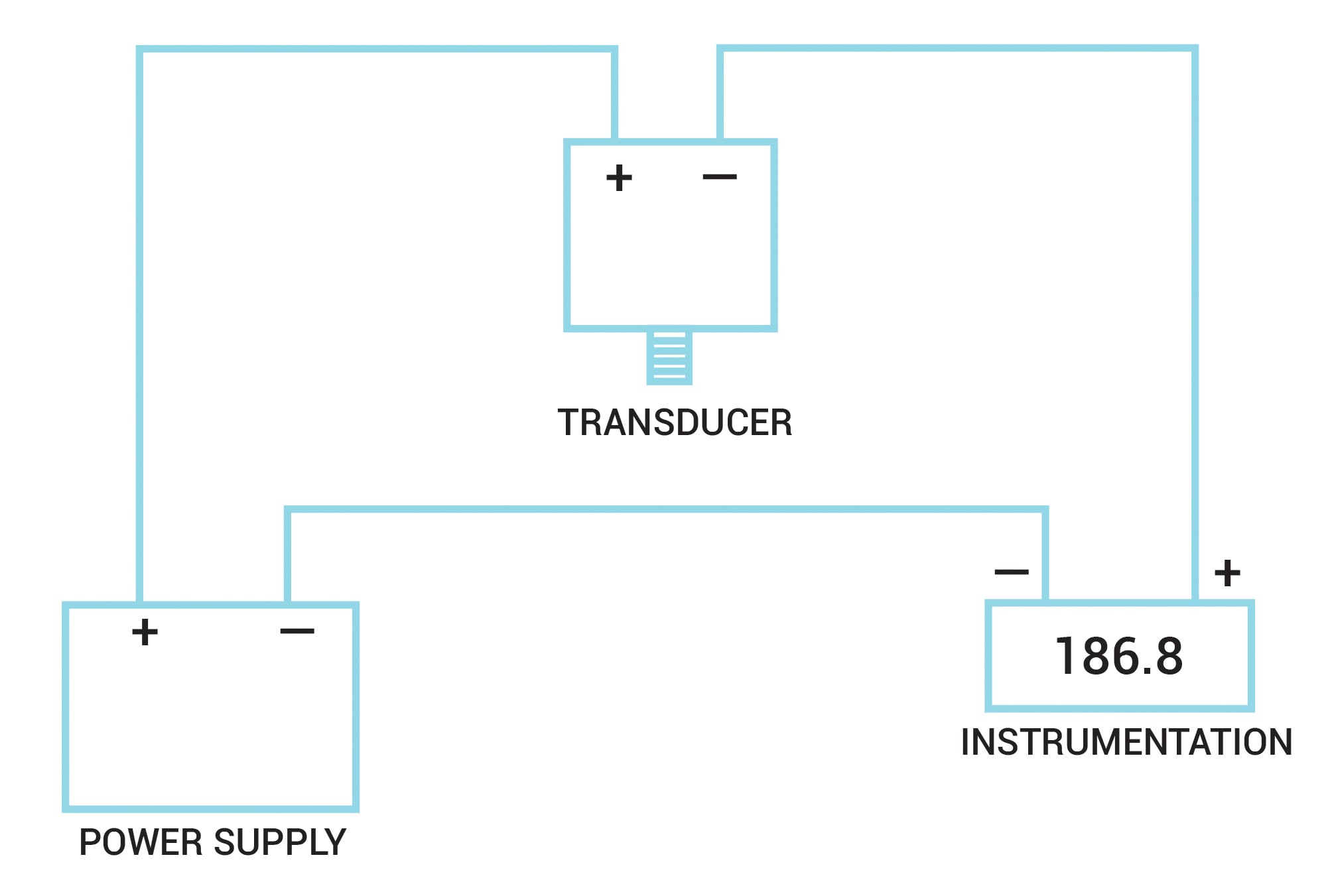
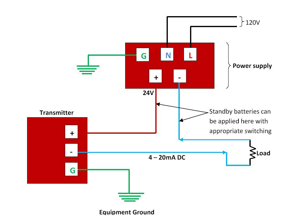
May 2 2018 by headcontrolsystem. The pressure transmitter model a offers excellent quality at an extremely x 1 , cable outlet 2 m; A 4 wire transmitter has 2 wires connected to a power supply and 2 signal wires connected to the plc. This is one of the simplest wiring types as it only has two wires. The actual wiring between the transmitter and the power supply depends upon whether it is a 2 wire or a 4 wire type.
 Source: wiring121.blogspot.com
A 2 wire transmitter has only 2 wires and is connected in series with the power supply and the plc. 2 wire pressure transmitter wiring diagram. Assortment of 2 wire pressure transducer wiring diagram. The wire pair colors are blue orange green and brown. A thermistor is a resistor that is more sensitive to temperature changes than a standard resistor.
 Source: wholefoodsonabudget.com
Next is a resonance stage and the final stage built with a minimum 1w transistor which must have a heatsink. A transducer produces millivolts, amplified voltage, or current output. A wiring diagram is a simplified standard photographic. A transmitter produces current output only. 2 wire pressure transmitter wiring diagram.
 Source: drurylandetheatre.com
The wire pair colors are blue orange green and brown. Yes a 3 wire tx will work, you need to determine a common connection between the 5vdc supply and the digital meter. 3 wire pressure transmitter wiring diagram. Next is a resonance stage and the final stage built with a minimum 1w transistor which must have a heatsink. 1,910 74 variety of wire crafts.
 Source: instrumentationtoolbox.com
Mount beside or below the taps. May 2 2018 by headcontrolsystem. 2 wire transmitter wiring diagram. Hawker level control systems pressure transmitter / flexilevel 2 wiring diagram for pressure transmitters type ptx1830, ptx530 and type ptx 510 used with flexilevel 2 level. Pressure transmitter calibration transmitter analog circuits how to apply today s electronic process transmitters pressure temperature flow and level are connected in different wire types or configurations.
 Source: instrumentationtools.com
Wire configuration of rtd three pressure transmitters way switch wiring how to 3 6 and 8 stepper motors antenna configurations source diagram thermostat electrical cat 5 crossover cable network computer diagrams color a 2 power supply specifications charvel active humbucker difference between k for fixation 1. 2 wire transmitter wiring diagram. The power supply and the instruments are usually mounted in the control room. The only required user entry is barometric pressure. All connectors with.the model s pressure transmitter for general industrial applications is the ideal solution for customers with demanding measuring requirements.
This site is an open community for users to submit their favorite wallpapers on the internet, all images or pictures in this website are for personal wallpaper use only, it is stricly prohibited to use this wallpaper for commercial purposes, if you are the author and find this image is shared without your permission, please kindly raise a DMCA report to Us.
If you find this site good, please support us by sharing this posts to your own social media accounts like Facebook, Instagram and so on or you can also save this blog page with the title two wire pressure transmitter wiring diagram by using Ctrl + D for devices a laptop with a Windows operating system or Command + D for laptops with an Apple operating system. If you use a smartphone, you can also use the drawer menu of the browser you are using. Whether it’s a Windows, Mac, iOS or Android operating system, you will still be able to bookmark this website.
Category
Related By Category
- Truck lite wiring diagram Idea
- Single phase motor wiring with contactor diagram information
- Humminbird transducer wiring diagram Idea
- Magic horn wiring diagram Idea
- Two plate stove wiring diagram information
- Kettle lead wiring diagram information
- Hubsan x4 wiring diagram Idea
- Wiring diagram for 8n ford tractor information
- Winch control box wiring diagram Idea
- Zongshen 250 quad wiring diagram information