Turn signal wiring diagram information
Home » Trend » Turn signal wiring diagram information
Your Turn signal wiring diagram images are available. Turn signal wiring diagram are a topic that is being searched for and liked by netizens now. You can Get the Turn signal wiring diagram files here. Get all royalty-free images.
If you’re searching for turn signal wiring diagram images information related to the turn signal wiring diagram topic, you have visit the ideal blog. Our website always provides you with hints for downloading the highest quality video and picture content, please kindly surf and locate more enlightening video articles and images that match your interests.
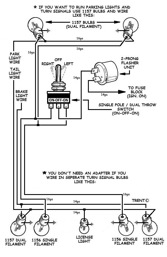
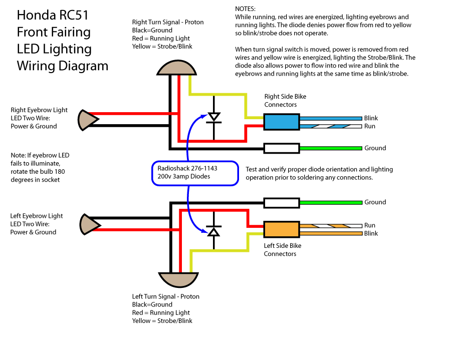
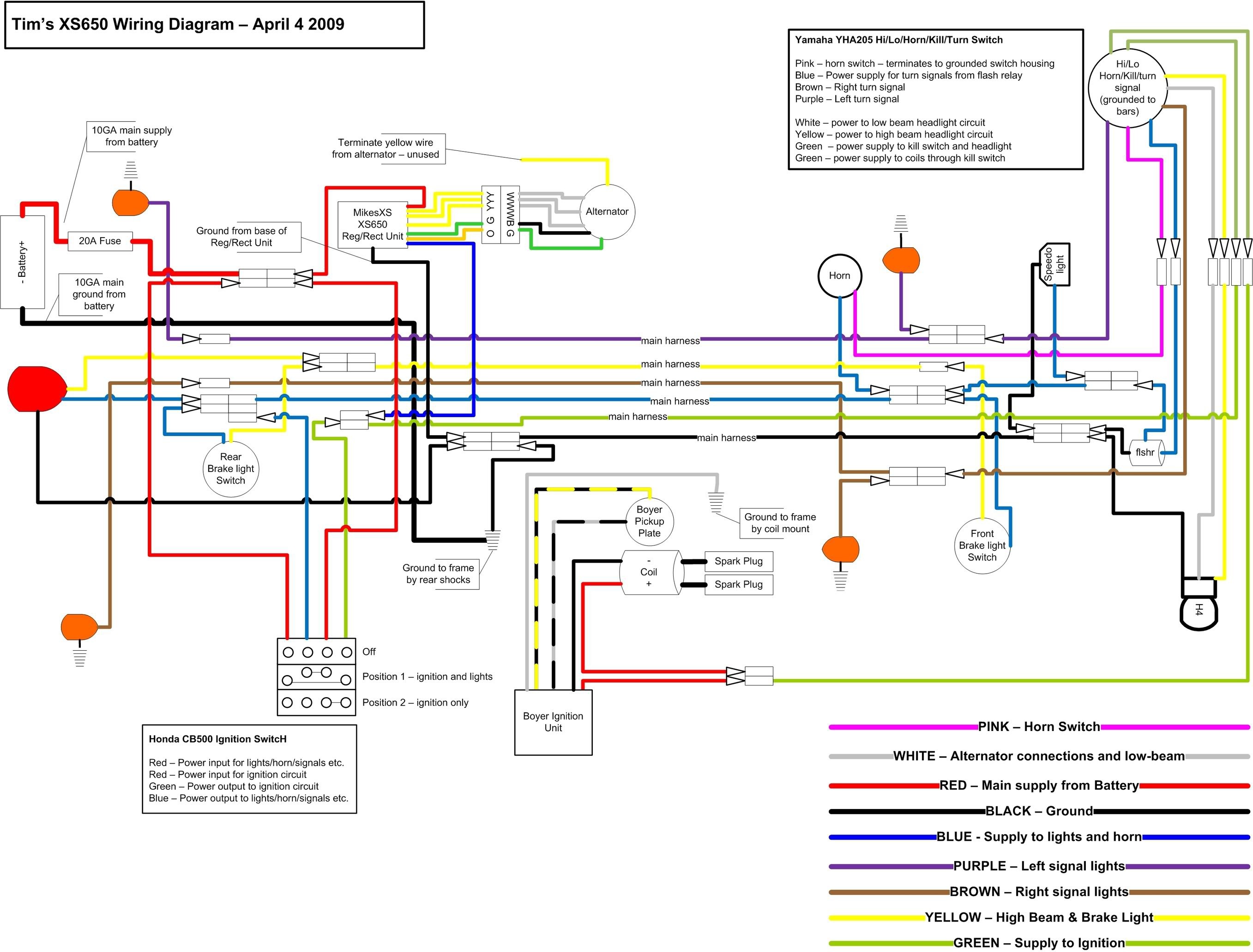
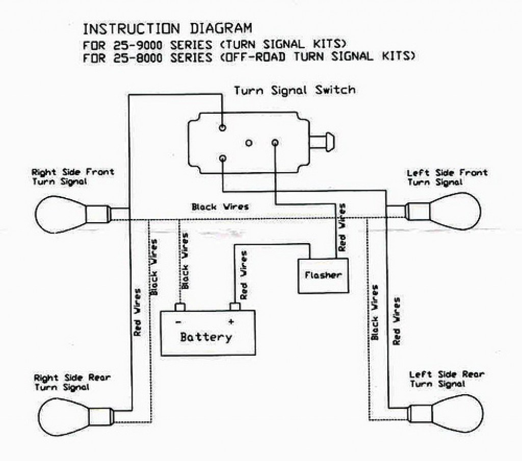
Turn Signal Wiring Diagram. Relay for turn signal/brake priority. A wiring diagram is a simple visual representation in the physical connections and physical layout associated with an electrical system or circuit. The other thing you will come across a circuit diagram could be traces. A circuit is usually composed by several components.
Projects Aftermarket signal switch KD728 help The H.A.M.B. From jalopyjournal.com
It really is intended to help all of the common person in developing a proper program. The other thing you will come across a circuit diagram could be traces. The power goes through a fuse panel into the thermal flasher. It is intended to aid each of the average person in developing a correct program. Club car ds wiring diagrams 1981 to 2002 golf cart tips. Wiring diagram arrives with numerous easy to stick to wiring diagram instructions.
Ground output wire through the rheostat.
Turn signal systems the wiring how signals work to add and wire them up. The following diagrams show some common relay wiring schemes that use 4 pin iso mini. As stated previous, the traces at a brake and turn signal wiring diagram signifies wires. Diagram 3456 7 8 9 functions headl dimmer 2 stop rn turn turn turn ight rear left rear left rear left front right rear i front hazard on Rhox byo club car precedent brake light kit with time delay jason s golf carts. For me the easy way would be to just run a third light for my brake light.
 Source: thecareandfeedingofponies.blogspot.com
$ save up to 10% when you buy more. Relay for turn signal/brake priority. Cj7 turn signal wiring diagram wiring diagram is a simplified all right pictorial representation of an electrical circuit it shows the components of the circuit as simplified shapes and the capability and signal links amongst the devices. Turn signal systems the wiring how signals work to add and wire them up. Wiring diagram arrives with numerous easy to stick to wiring diagram guidelines.
 Source: faceitsalon.com
From there it goes to the stalk on the steering column. These instructions will likely be easy to comprehend and use. Left turn signal wiring diagram light blue (left front ts) yellow (left rear ts) green (right rear ts) 4 brown (hazards) not connected +12v, white (brake lts) always connected (controlled by brake pedal) +12v, purple (turn signal power) turn signal power (purple) connected to left side turn signals (light blue, yellow). Heres the 82 pontiac rwd car shop manual wiring diagram for the turn signal switch. Variety of universal turn signal wiring diagram.
 Source: how-to-build-hotrods.com
Ground output wire through the rheostat. Variety of universal turn signal wiring diagram. Gm turn signal switch wiring diagram from www.justanswer.com effectively read a cabling diagram, one has to find out how typically the components inside the method operate. 8 wire turn signal diagram detailed login instructions loginnote utv lighting kit installation tusk horn and signal utilizing the stock led s as turn signal brake hazard lights prc polaris ranger club Some have the tail light wire running through them (4 wire into 3 wire), and some don�t (3 wire into 2 wire).
Source: prsteyer.blogspot.com
8 wire turn signal diagram detailed login instructions loginnote utv lighting kit installation tusk horn and signal utilizing the stock led s as turn signal brake hazard lights prc polaris ranger club Turn signal switch with horn on 7 wire. What you need to do is find. $ save up to 10% when you buy more. Ground output wire through the rheostat.
![[DIAGRAM] Utv Turn Signal Wiring Diagram FULL Version HD [DIAGRAM] Utv Turn Signal Wiring Diagram FULL Version HD](https://ricardolevinsmorales.com/wp-content/uploads/2018/09/universal-turn-signal-wiring-diagram-universal-turn-signal-switch-wiring-diagram-12h.jpg) Source: reviewdiagram99.puliziasconfinata.it
Source: reviewdiagram99.puliziasconfinata.it
8 wire turn signal diagram detailed login instructions loginnote utv lighting kit installation tusk horn and signal utilizing the stock led s as turn signal brake hazard lights prc polaris ranger club 8 wire turn signal diagram detailed login instructions loginnote utv lighting kit installation tusk horn and signal utilizing the stock led s as turn signal brake hazard lights prc polaris ranger club It contains directions and diagrams for various types of wiring techniques and other items like lights, windows, and so forth. The following diagrams show some common relay wiring schemes that use 4 pin iso mini. We also have some more figures linked to honda cx500 wiring diagram further lincoln.
 Source: schematicandwiringdiagram.blogspot.com
$ save up to 10% when you buy more. Now, do the rear brake light wires go to the bulb via tapping into the i am attaching a diagram i found on google. Yamaha golf cart turn signal 01 2022. Wiring diagram arrives with numerous easy to stick to wiring diagram instructions. A circuit is usually composed by several components.
Source: kovodym.blogspot.com
All of gm turn switches from about 69 up into the late 80s are pretty much the same wiring. For instance , in case a module is powered up and it sends out the signal of half the voltage in addition to the technician will not know this, he�d think he offers a. Tsg unv 2463k universal turn signal wiring kit updated indd. But, it does not mean link between the wires. Club car ds wiring diagrams 1981 to 2002 golf cart tips.
 Source: speedzilla.com
$ save up to 10% when you buy more. All of gm turn switches from about 69 up into the late 80s are pretty much the same wiring. Gm turn signal switch wiring diagram. Lgt 112 and 112a wiring diagram rev031416. Basic turn signal wiring diagram basic turn signal wiring diagram.
 Source: klveducation.org
Left turn signal wiring diagram light blue (left front ts) yellow (left rear ts) green (right rear ts) 4 brown (hazards) not connected +12v, white (brake lts) always connected (controlled by brake pedal) +12v, purple (turn signal power) turn signal power (purple) connected to left side turn signals (light blue, yellow). 10l0l golf cart turn signal kit with horn brake hazard light switch 9 pin plug upgrade wiring harness 12v for club car ezgo yamaha com. We also have some more figures linked to honda cx500 wiring diagram further lincoln. Motorcycle 3 pin turn signal wire adapters plugs for honda cbr rr see more like this. $ save up to 10% when you buy more.
 Source: tops-stars.com
The following simplified circuit diagram is often used to easily understand how a relay operates: Wiring diagram arrives with numerous easy to stick to wiring diagram guidelines. Make your own switch system. Golf cart turn signal switch w flasher relay pete s carts. It is intended to aid each of the average person in developing a correct program.

Diagram 3456 7 8 9 functions headl dimmer 2 stop rn turn turn turn ight rear left rear left rear left front right rear i front hazard on Left turn signal wiring diagram light blue (left front ts) yellow (left rear ts) green (right rear ts) 4 brown (hazards) not connected +12v, white (brake lts) always connected (controlled by brake pedal) +12v, purple (turn signal power) turn signal power (purple) connected to left side turn signals (light blue, yellow). Cj7 turn signal wiring diagram wiring diagram is a simplified all right pictorial representation of an electrical circuit it shows the components of the circuit as simplified shapes and the capability and signal links amongst the devices. Club car ds wiring diagrams 1981 to 2002 golf cart tips. Some have the tail light wire running through them (4 wire into 3 wire), and some don�t (3 wire into 2 wire).
 Source: tops-stars.com
But, it does not mean link between the wires. The following diagrams show some common relay wiring schemes that use 4 pin iso mini. 8 wire turn signal diagram detailed login instructions loginnote utv lighting kit installation tusk horn and signal utilizing the stock led s as turn signal brake hazard lights prc polaris ranger club The one automotive job we all dread is the wiring. For instance , in case a module is powered up and it sends out the signal of half the voltage in addition to the technician will not know this, he�d think he offers a.
 Source: tlzone.net
Relay for turn signal/brake priority. The first element is symbol that indicate electrical component in the circuit. 7 wire turn signal switch wiring diagram.it�s kind of dink dink or cheap but it�ll do the trick. It contains directions and diagrams for various types of wiring techniques and other items like lights, windows, and so forth. This really is beneficial for each the folks and for specialists who are searching for more information regarding how to set up a working atmosphere.
 Source: tops-stars.com
Gm turn signal switch wiring diagram. Comment & subcribe :)�do it at your own risk�follow me onfacebook: Want to add turn signals to your hotrod? This really is beneficial for each the folks and for specialists who are searching for more information regarding how to set up a working atmosphere. Now, do the rear brake light wires go to the bulb via tapping into the i am attaching a diagram i found on google.
 Source: schematicdiagram67.blogspot.com
The one automotive job we all dread is the wiring. We also have some more figures linked to honda cx500 wiring diagram further lincoln. Some have the tail light wire running through them (4 wire into 3 wire), and some don�t (3 wire into 2 wire). The one automotive job we all dread is the wiring. Gm turn signal switch wiring diagram from www.justanswer.com effectively read a cabling diagram, one has to find out how typically the components inside the method operate.
 Source: 2020cadillac.com
Gm turn signal switch wiring diagram. Comment & subcribe :)�do it at your own risk�follow me onfacebook: Motorcycle 3 pin turn signal wire adapters plugs for honda cbr rr see more like this. Tsg unv 2463k universal turn signal wiring kit updated indd. But, it does not mean link between the wires.
Source: jalopyjournal.com
This really is beneficial for each the folks and for specialists who are searching for more information regarding how to set up a working atmosphere. A circuit is usually composed by several components. For me the easy way would be to just run a third light for my brake light. These guidelines will be easy to comprehend and implement. All of gm turn switches from about 69 up into the late 80s are pretty much the same wiring.
Source: ford-trucks.com
Injunction of 2 wires is usually indicated by black dot at the intersection of 2 lines. How to add turn signals and wire them up. Some have the tail light wire running through them (4 wire into 3 wire), and some don�t (3 wire into 2 wire). The power goes through a fuse panel into the thermal flasher. (it�s easy!) factory switchmost of you will have a hotrod that uses a steering column that has a turn signal switch built in.
This site is an open community for users to submit their favorite wallpapers on the internet, all images or pictures in this website are for personal wallpaper use only, it is stricly prohibited to use this wallpaper for commercial purposes, if you are the author and find this image is shared without your permission, please kindly raise a DMCA report to Us.
If you find this site serviceableness, please support us by sharing this posts to your own social media accounts like Facebook, Instagram and so on or you can also save this blog page with the title turn signal wiring diagram by using Ctrl + D for devices a laptop with a Windows operating system or Command + D for laptops with an Apple operating system. If you use a smartphone, you can also use the drawer menu of the browser you are using. Whether it’s a Windows, Mac, iOS or Android operating system, you will still be able to bookmark this website.
Category
Related By Category
- Predator 670 engine wiring diagram Idea
- Frsky x8r wiring diagram information
- Pioneer ts wx130da wiring diagram Idea
- Johnson 50 hp wiring diagram Idea
- Kohler voltage regulator wiring diagram Idea
- Johnson 50 hp outboard wiring diagram information
- Kti hydraulic remote wiring diagram Idea
- Pyle plpw12d wiring diagram information
- Tx9600ts wiring diagram information
- Lifan 50cc wiring diagram information