Tube light wiring circuit diagram information
Home » Trend » Tube light wiring circuit diagram information
Your Tube light wiring circuit diagram images are ready. Tube light wiring circuit diagram are a topic that is being searched for and liked by netizens now. You can Download the Tube light wiring circuit diagram files here. Download all royalty-free vectors.
If you’re looking for tube light wiring circuit diagram images information connected with to the tube light wiring circuit diagram interest, you have come to the right site. Our website frequently provides you with hints for refferencing the highest quality video and image content, please kindly hunt and locate more informative video articles and graphics that fit your interests.
Tube Light Wiring Circuit Diagram. If you want do it yourself (diy), you can buy all the parts individually. Wiring diagram fluorescent led lighting. Wiring diagram of a one way lighting circuit using junction boxes (fig 1). Switch it on and enjoy the soft light.
 Wiring Diagram Of Fluorescent Sign Wiring Diagram Schemas From wiringschemas.blogspot.com
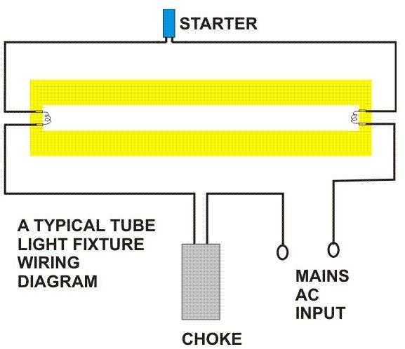
A wire already connects port 2 and pin 1 of the. It shows the components of the circuit as simplified shapes and the talent and signal connections amongst the devices. You can also see that another live and neutral wire go to the next. Two tube with one ballast (choke) wiring diagram here in this tube light wiring diagram you will find two fluorescent tubes are connected with one choke or ballast, two. This can be useful for each the folks and for experts that are searching to learn more regarding how to set up a working surroundings. From the ceiling box an electrical receptacle outlet is fed power.
Please refer to the circuit diagram on the right as you read the following points:
It shows the components of the circuit as simplified shapes and the talent and signal connections amongst the devices. From the junction box the neutral wire is not taken out to the switch board, rather it is taken out from the junction box and carried out to the port 2 of the tube light, as per figure above. The diagram above shows a two conductor cable from the circuit breaker panel going to a wall switch. The driver circuit divides a string of 25 leds into two sets of five one set of four and one set of six. The gap between the led�s should be 1 inch so as to cover the 4 feet of pvc batten. Your tube light is ready.
 Source: brighthubengineering.com
Osram led tube wiring diagram. Tube light connection diagram tube lights are most used light source and here tube light connection circuit and wiring diagram given with. The tube light or fluorescent light is a low pressure mercury vapor gas discharge lamp and it uses fluorescent to produce white light. Follow the circuit diagram in detail. Two tube with one ballast (choke) wiring diagram here in this tube light wiring diagram you will find two fluorescent tubes are connected with one choke or ballast, two.
 Source: etsytivity.blogspot.com
The driver circuit divides a string of 25 leds into two sets of five one set of four and one set of six. The tube light or fluorescent light is a low pressure mercury vapor gas discharge lamp and it uses fluorescent to produce white light. The permanent live wire is wired into the switch and the switched live into the switched live terminal. Fig 2 explanation of above picture. So the neutral wire is continued from port 2 to pin 1 of terminal 2.
 Source: schematron.org
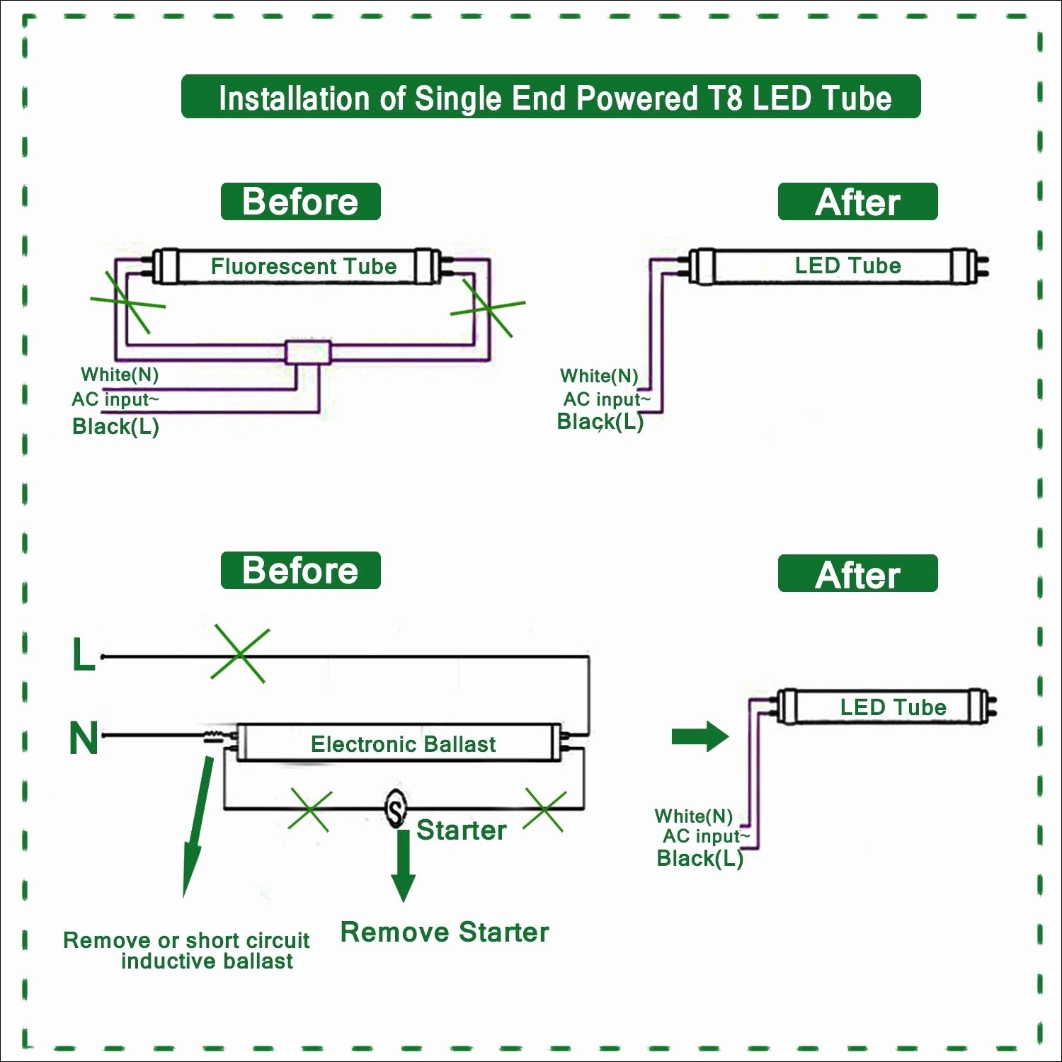
The tube light or fluorescent light is a low pressure mercury vapor gas discharge lamp and it uses fluorescent to produce white light. Electronic ballast tube light wiring diagram connection and working we need tube light, ballast, starter and fluorescent light holders to make wiring connection. The 3 segments should be connected in parallel to the house ac outlet. Philips led tube wiring diagram led tube light wiring diagram single light wiring diagram t8 led lam led fluorescent tube fluorescent tube led fluorescent. Working principle of tube light.
 Source: annawiringdiagram.com
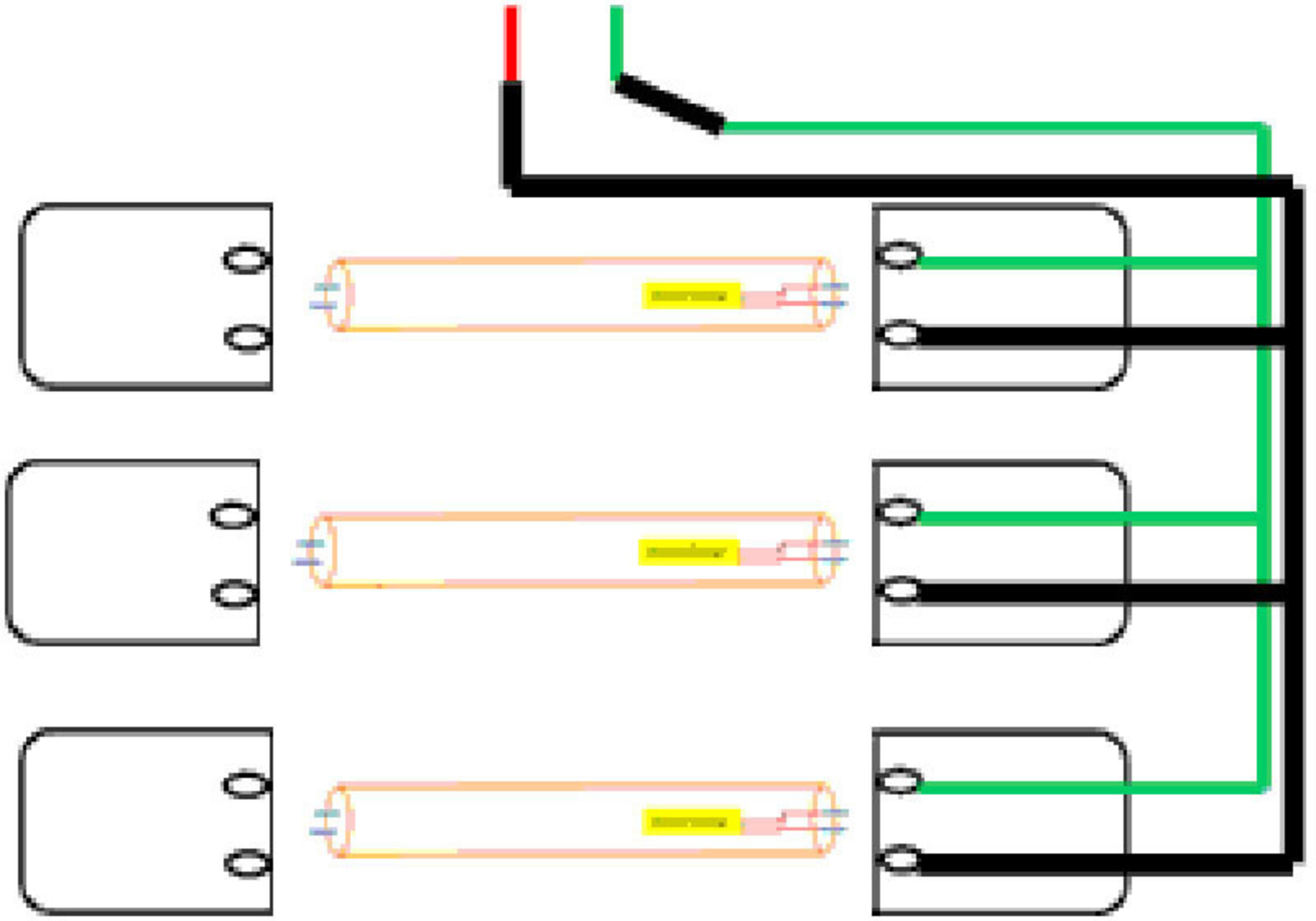
The neutrals are connected together using a terminal connector. Wiring diagram fluorescent led lighting. Wiring diagram here two tube lights are used, in our case each one is 20 watts, each tube light will have two filament with four terminals, connect starter element to any on side of tube light , after that link phase line to the ballast (choke) through switch. The wiring process of fluorescent tube lamp/light with ballast, starter is. The gap between the led�s should be 1 inch so as to cover the 4 feet of pvc batten.
 Source: theorycircuit.com
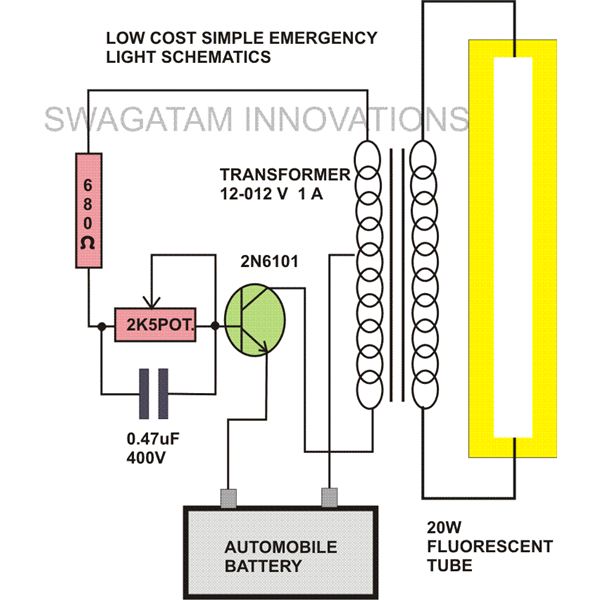
Different electrical symbols are used to make the wiring diagram below: You can also see that another live and neutral wire go to the next. From the junction box the neutral wire is not taken out to the switch board, rather it is taken out from the junction box and carried out to the port 2 of the tube light, as per figure above. A wiring diagram is a streamlined standard pictorial depiction of an electrical circuit. The circuit diagram shown above is quite simplified from basic tube light wiring diagram by adding a bridge rectifier.
 Source: pertronix-wiring-diagram94.blogspot.com
Wiring diagram for led tube lights. Get instant quality results now. Wiring diagram for led tube lights sample 30 beautiful outdoor lamp post wiring diagram light and lighting 2018. Different electrical symbols are used to make the wiring diagram below: Led fluorescent tube replacement wiring diagram youll need an extensive expert and easy to know wiring diagram.
 Source: homemade-circuits.com
Working principle of tube light. In most cases when we buy a fluorescent light it comes in a complete set with all wire connected. In most cases when we buy a fluorescent light it comes in a. Philips led tube wiring diagram led tube light wiring diagram single light wiring diagram t8 led lam led fluorescent tube fluorescent tube led fluorescent. This can be useful for each the folks and for experts that are searching to learn more regarding how to set up a working surroundings.
 Source: annawiringdiagram.com
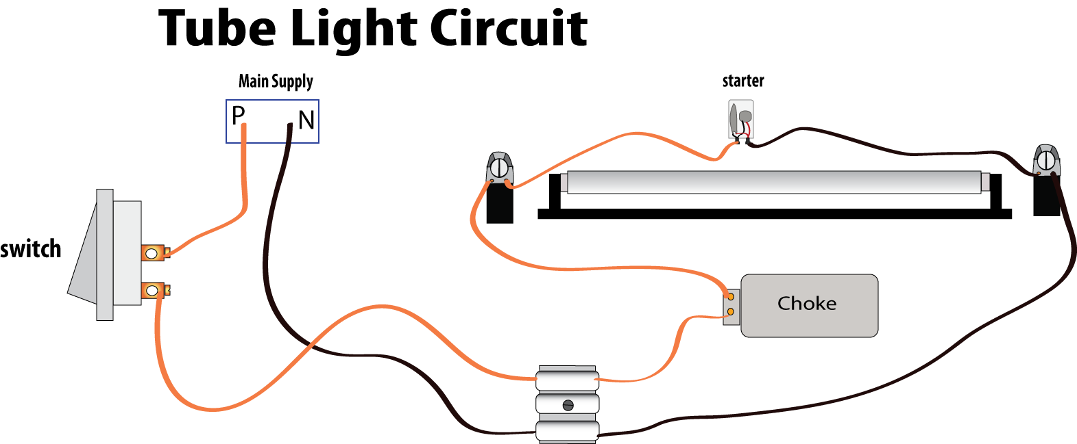
The 3 segments should be connected in parallel to the house ac outlet. Fig 1 the junction box should be wired as shown below. A wire already connects port 2 and pin 1 of the. Here is one example of a tube light fixture consisting of a large heavy square “choke” or “ballast” and a small cylindrical “starter.” let’s try to understand how the whole system works. From the ceiling box an electrical receptacle outlet is fed power.
Source: wiringschemas.blogspot.com
Tube light connection diagram tube lights are most used light source and here tube light connection circuit and wiring diagram given with. Led fluorescent tube replacement wiring diagram youll need an extensive expert and easy to know wiring diagram. The starter is made up of a discharbe bulb with two electrodes next to it. Wiring diagram for led tube lights sample 30 beautiful outdoor lamp post wiring diagram light and lighting 2018. Wiring of fluorescent lamp circuit in electrical installation work.
 Source: wholefoodsonabudget.com
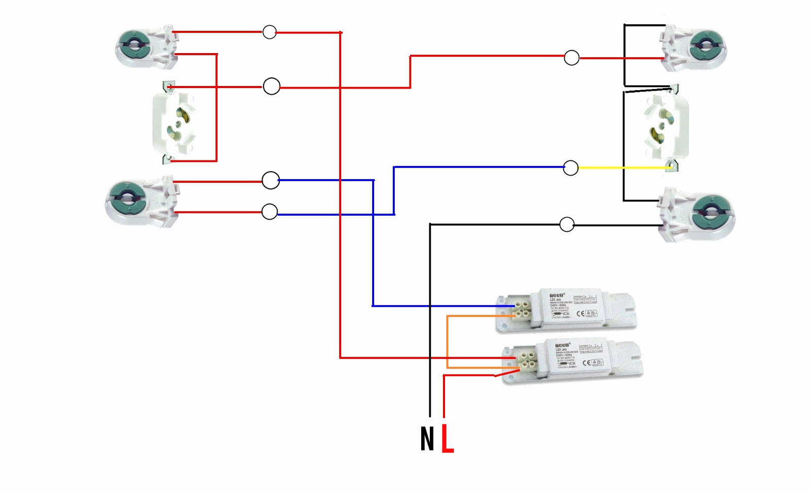
Follow the circuit diagram in detail. Two tube with one ballast (choke) wiring diagram here in this tube light wiring diagram you will find two fluorescent tubes are connected with one choke or ballast, two separate starters are used for each tube and finally connected to 230v power supply through a switch. Wiring diagram of a one way lighting circuit using junction boxes (fig 1). In most cases when we buy a fluorescent light it comes in a. From the examples below identify the wiring configuration of your fixture which is a function of the ballast type.
 Source: wiringschemas.blogspot.com
Wiring diagram for led tube lights sample 30 beautiful outdoor lamp post wiring diagram light and lighting 2018. Led fluorescent tube replacement wiring diagram youll need an extensive expert and easy to know wiring diagram. Wiring diagram fluorescent led lighting. There will be three sorts of wires. Fig 2 explanation of above picture.
 Source: wiringschemas.blogspot.com
In most cases when we buy a fluorescent light it comes in a. Bridge rectifier provides high voltage dc to the both end of tube. During normal light in the day ie. There will be three sorts of wires. Follow the circuit diagram in detail.
 Source: schematron.org
Please refer to the circuit diagram on the right as you read the following points: Wiring diagram here two tube lights are used, in our case each one is 20 watts, each tube light will have two filament with four terminals, connect starter element to any on side of tube light , after that link phase line to the ballast (choke) through switch. Assortment of fluorescent ballast wiring diagram. It shows the components of the circuit as simplified shapes and the talent and signal connections amongst the devices. Removing the ballast cover allows you to access the tombstones and the wiring.
 Source: pinterest.es
In most cases when we buy a fluorescent light it comes in a complete set with all wire connected. Led fluorescent tube replacement wiring diagram youll need an extensive expert and easy to know wiring diagram. Assortment of fluorescent ballast wiring diagram. This diagram illustrates wiring for one switch to control 2 or more lights. October 31 2018 by larry a.
 Source: pinterest.com
Light switch wiring diagram depicted here shows the power from the circuit breaker panel going to a wall switch and then continues to a ceiling light with a three conductor cable. Different electrical symbols are used to make the wiring diagram below: You can see the one terminal of each filament is connected through a starter. A wiring diagram is a streamlined standard pictorial depiction of an electrical circuit. Two tube with one ballast (choke) wiring diagram here in this tube light wiring diagram you will find two fluorescent tubes are connected with one choke or ballast, two.
 Source: pinterest.com
The gap between the led�s should be 1 inch so as to cover the 4 feet of pvc batten. A wiring diagram is a streamlined standard pictorial depiction of an electrical circuit. As we all know led tube light and led bulbs are very famous now a days. Light switch wiring diagram depicted here shows the power from the circuit breaker panel going to a wall switch and then continues to a ceiling light with a three conductor cable. Two tube with one ballast (choke) wiring diagram here in this tube light wiring diagram you will find two fluorescent tubes are connected with one choke or ballast, two separate starters are used for each tube and finally connected to 230v power supply through a switch.
 Source: worldvisionsummerfest.com
You can also see that another live and neutral wire go to the next. The hot and neutral terminals on each fixture are spliced with a pigtail to the circuit wires which then continue on to the next light. A wire already connects port 2 and pin 1 of the. Your tube light is ready. There will be three sorts of wires.
 Source: keelapavoorengineersclub.blogspot.com
A wiring diagram is a streamlined standard pictorial depiction of an electrical circuit. Follow the circuit diagram in detail. Wiring diagram of a one way lighting circuit using junction boxes (fig 1). Direct wiring circuit diagram of a retrofitted. The gap between the led�s should be 1 inch so as to cover the 4 feet of pvc batten.
This site is an open community for users to do sharing their favorite wallpapers on the internet, all images or pictures in this website are for personal wallpaper use only, it is stricly prohibited to use this wallpaper for commercial purposes, if you are the author and find this image is shared without your permission, please kindly raise a DMCA report to Us.
If you find this site value, please support us by sharing this posts to your own social media accounts like Facebook, Instagram and so on or you can also bookmark this blog page with the title tube light wiring circuit diagram by using Ctrl + D for devices a laptop with a Windows operating system or Command + D for laptops with an Apple operating system. If you use a smartphone, you can also use the drawer menu of the browser you are using. Whether it’s a Windows, Mac, iOS or Android operating system, you will still be able to bookmark this website.
Category
Related By Category
- Predator 670 engine wiring diagram Idea
- Frsky x8r wiring diagram information
- Pioneer ts wx130da wiring diagram Idea
- Johnson 50 hp wiring diagram Idea
- Kohler voltage regulator wiring diagram Idea
- Johnson 50 hp outboard wiring diagram information
- Kti hydraulic remote wiring diagram Idea
- Pyle plpw12d wiring diagram information
- Tx9600ts wiring diagram information
- Lifan 50cc wiring diagram information