Traffic light diagram wiring information
Home » Trending » Traffic light diagram wiring information
Your Traffic light diagram wiring images are ready in this website. Traffic light diagram wiring are a topic that is being searched for and liked by netizens today. You can Find and Download the Traffic light diagram wiring files here. Find and Download all free photos and vectors.
If you’re searching for traffic light diagram wiring images information related to the traffic light diagram wiring interest, you have visit the ideal site. Our website frequently gives you hints for seeking the highest quality video and picture content, please kindly search and locate more informative video content and graphics that match your interests.
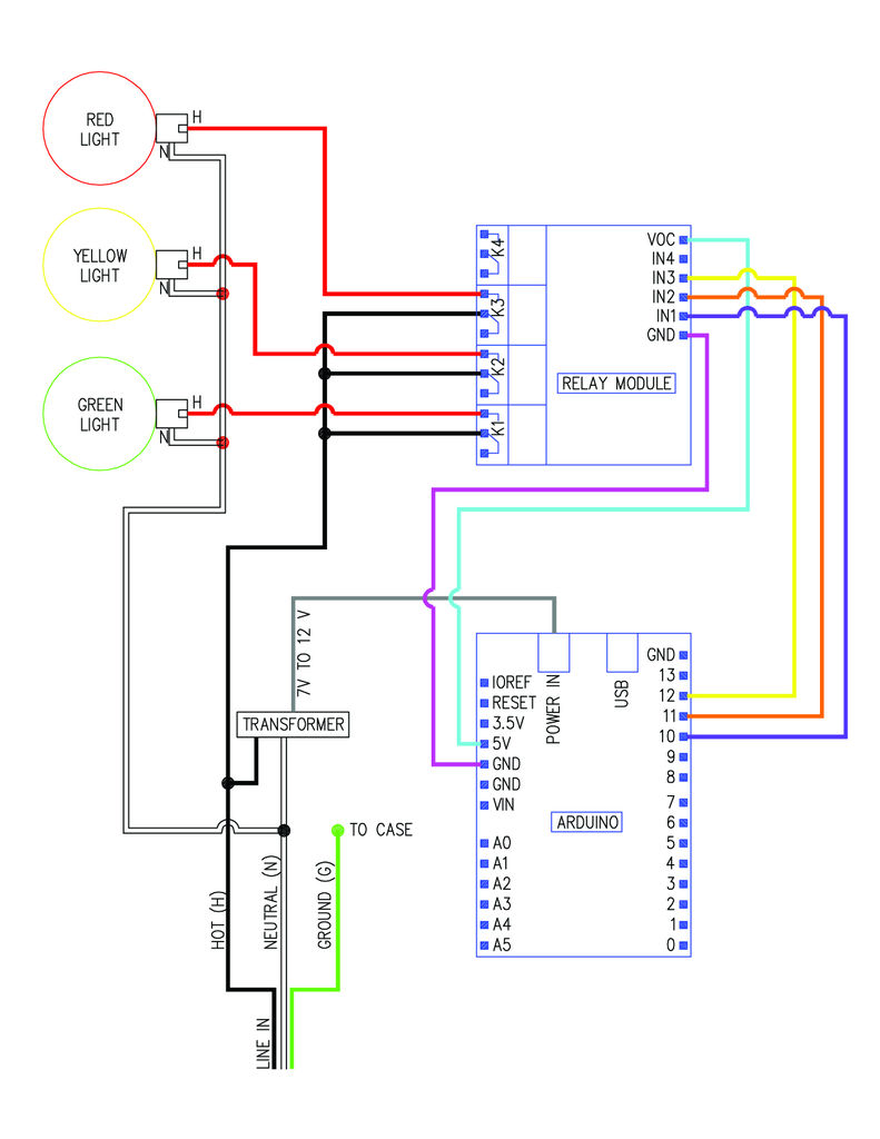
Traffic Light Diagram Wiring. Using time delay relays to cycle a traffic signal simple four way light circuit ic 555 1 main diagram of controller scientific lights for model cars or railways and rpi plc connections timer sigmatone nick viera manual on controls diy home improvement forum. Wiring diagram for traffic lights. 4 way traffic lights diagram electronic schematics led projects traffic light. By irish bella | august 10, 2021.
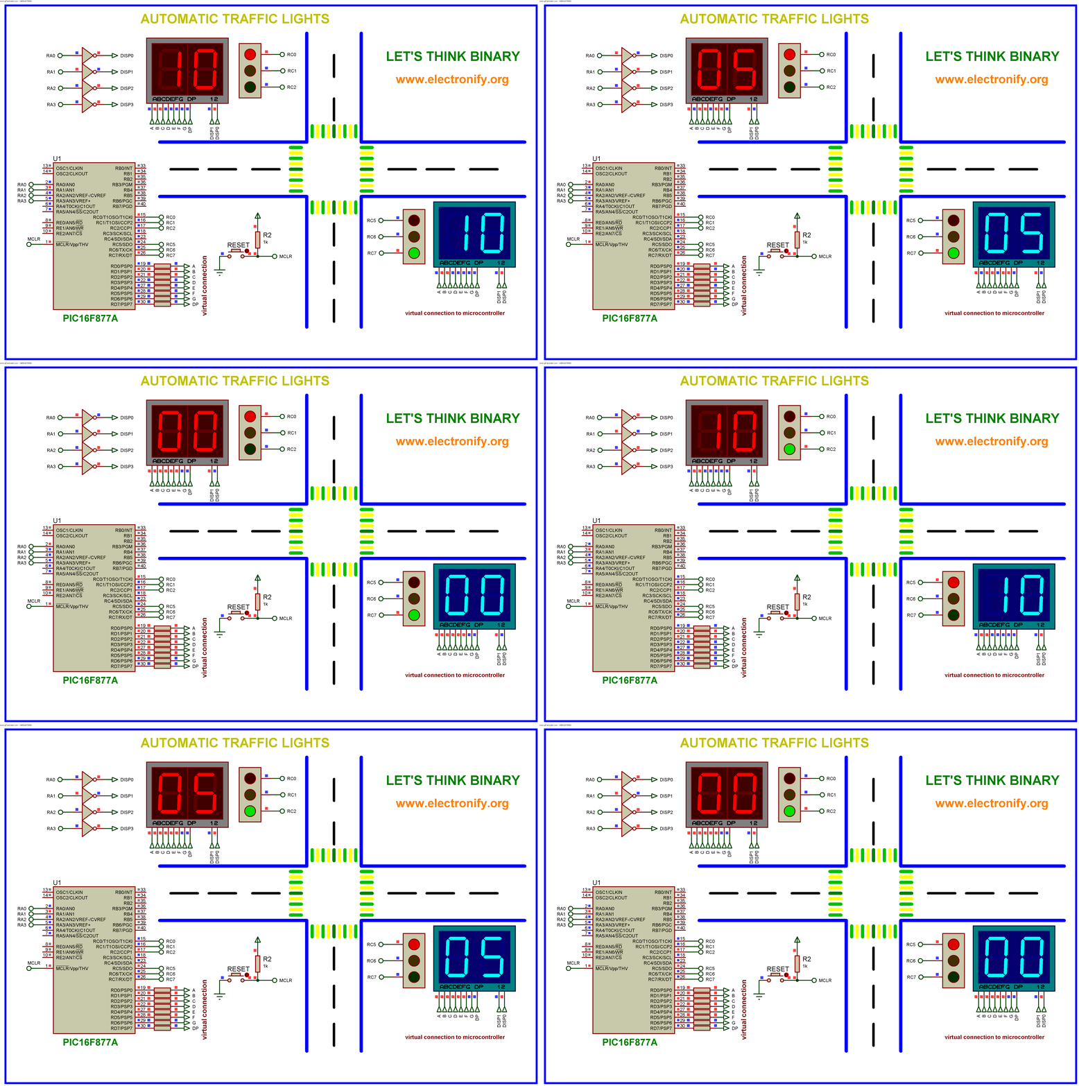 Automatic traffic light using PIC16F877A Microcontroller From pic-microcontroller.com
One of the principal jobs of a system administrator. Simple four way traffic light circuit using ic 555 diagram timer lights density based signal system microcontroller atmega32 avr two and cd4017 electronics area controller. Circuit diagram of traffic light and rpi plc connections. Green to amber steady w/relay 4 flashing to red w/relay 4 steady, and back to green. I am a student with a homework assignment, basic wiring with a timer, etc. 4 way traffic lights diagram electronic schematics traffic.
Ed grabianowski advertisement please copy/pa.
Working with a sharp knife, make holes opposite the outlets carefully. Well everyone first and foremost i want to state i am not an electrician but have some understanding on how things work and this is what i did to make this s. We know each traffic signal light setup will have three colors and representing red for stop, yellow for wait, and green for go, those signals are works based on time intervals. Automatic traffic light controller 4 way traffic signal control system proteus project in 2021 lighting control system traffic signal traffic light. The timer here generates pulses of time period 100ms approximately. I also wanted to try out an arduino controller and thought this would be.
Source: wiringschemas.blogspot.com
Envirementalb com electronic circuit projects traffic light electronics circuit. 4 way traffic lights diagram electronic schematics led projects traffic light. Wiring harness 12v hid lights led light bars 2x wires bar a wiring diagram is a simplified standard photographic representation of an electric circuit. Wiring diagram a, switch setting 31. Use this sequence for controlling a traffic light with a walk, don�t walk signal and flashing don�t walk.
 Source: wiringschemas.blogspot.com
System in accordance with the field wiring diagram shown in the plans. Arduino gps speedometer with a ks0108 128×64 glcd display arduino gps arduino arduino projects. Two timer ics biased with 12 volt power supply, the left side timer provides output through red led, the right side timer led provides output through yellow led. If you feel strongly about the need for a traffic light in your neighborhood, you have a right to petition for one. 4 way traffic lights diagram electronic schematics traffic.
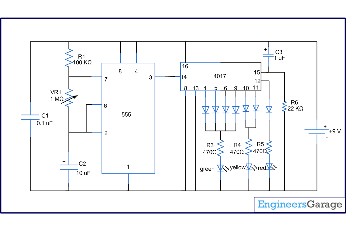 Source: engineersgarage.com
Traffic light is designed with two timer ics 555 and three led indicators, this circuit drives three leds with different time delay to provide stop, wait, and go signals on road. They can include three, four, or five different lenses in varying patterns. Connect the connector wires accordingly. June 2, 2019 1 0. Simple four way traffic light circuit 4 lights diagram using 555 timer ic help all controller jose pino s projects two schematics com the language sigmatone.
 Source: kovodym.blogspot.com
Traffic lights for model cars or model railways circuit schematic. 4 way traffic light schematic diagram. By irish bella | august 10, 2021. June 2, 2019 1 0. Place the wiring diagram in the signed cabinet at.
 Source: wiringview.co
Support the other ends of the tubes in the holes made on the front panel of cardboard box. Simple four way traffic light circuit 4 lights diagram using 555 timer ic help all controller jose pino s projects two schematics com the language sigmatone. I always wanted an old traffic signal and finally got one recently. There are three control lights or signals, which will provide the instruction to the driver. Garage genie parking remote control.
 Source: wiring89.blogspot.com
Www.circuitous.ca read electrical wiring diagrams from unfavorable to positive and redraw the signal being a straight collection. Wiring diagram and schematic role. 4 way traffic light schematic diagram. Using time delay relays to cycle a traffic signal simple four way light circuit ic 555 1 main diagram of controller scientific lights for model cars or railways and rpi plc connections timer sigmatone nick viera manual on controls diy home improvement forum. One of the principal jobs of a system administrator.
 Source: wiring89.blogspot.com
Using time delay relays to cycle a traffic signal simple four way light circuit ic 555 1 main diagram of controller scientific lights for model cars or railways and rpi plc connections timer sigmatone nick viera manual on controls diy home improvement forum. Wiring diagram for traffic lights. Please like,subscribe, share & click the notification bell for new uploading videos on my channel. Use this sequence for controlling a traffic light with a walk, don�t walk signal and flashing don�t walk. I always wanted an old traffic signal and finally got one recently.
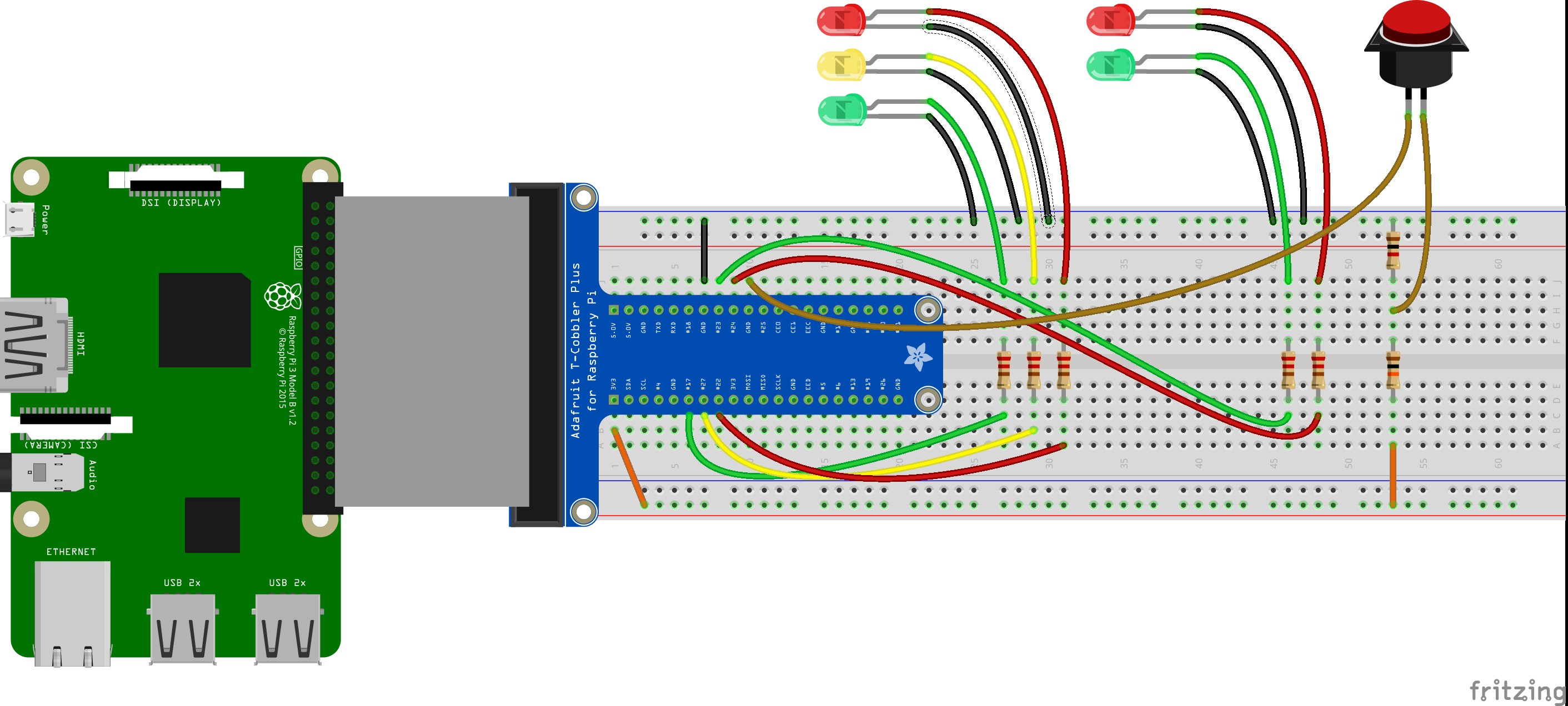 Source: galvinconanstuart.blogspot.com
Additionally, auto table/cadig shall be used to. To control the red, yellow, and green leds of the traffic lights, the leds need to be supplied with a common positive (+) current, connected to the anode of each led. I always wanted an old traffic signal and finally got one recently. Well everyone first and foremost i want to state i am not an electrician but have some understanding on how things work and this is what i did to make this s. Wiring diagram for traffic lights.
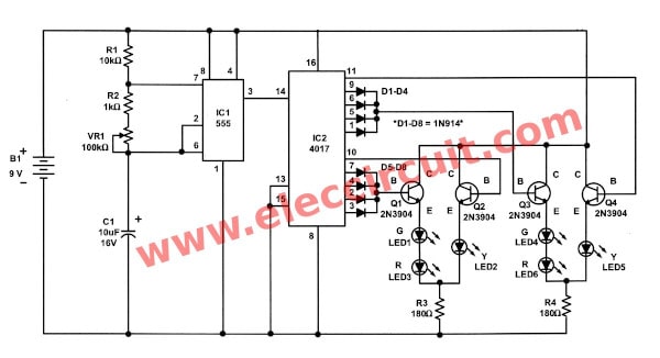 Source: eleccircuit.com
Wiring diagram and schematic role. Four circuit controller function 1. Use this sequence for controlling a traffic light with a walk, don�t walk signal and flashing don�t walk. There are three control lights or signals, which will provide the instruction to the driver. Www.circuitous.ca read electrical wiring diagrams from unfavorable to positive and redraw the signal being a straight collection.
 Source: wiringschemas.blogspot.com
Traffic light wiring diagram from www.engineersgarage.com. This clock pulse is feed to ic 4017 which is a counter ic. Garage genie parking remote control. Ed grabianowski advertisement please copy/pa. Wiring harness 12v hid lights led light bars 2x wires bar a wiring diagram is a simplified standard photographic representation of an electric circuit.
 Source: duino4projects.com
Use this sequence for controlling a traffic light with a walk, don�t walk signal and flashing don�t walk. The timer here generates pulses of time period 100ms approximately. Traffic light circuit diagram using 555 timer ic. Green to amber steady w/relay 4 flashing to red w/relay 4 steady, and back to green. They can include three, four, or five different lenses in varying patterns.
 Source: pic-microcontroller.com
Traffic light wiring diagram from www.engineersgarage.com. Support the other ends of the tubes in the holes made on the front panel of cardboard box. Simple four way traffic light circuit 4 lights diagram using 555 timer ic help all controller jose pino s projects two schematics com the language sigmatone. It includes information such as the title block, project. Traffic lights controller light using tranistors simple sigmatone circuit diagram 555 timer ic four way control system working its applications 8051 microcontroller gadgetronicx cd4027 ne555 and cd4017 electroduino complete of the designed microconroller based scientific schematics com project with rtc engineers gallery for density eceprojects signal pic16f84a.
Source: next.gr
Place the negative terminal of the leds in common and connect the 220ohm resistor in series. Traffic signal lights are very important to regulate vehicles and traffic on roads, simple four way traffic light circuit is designed with timer ic 555 and counter ic cd4017. Traffic lights for model cars or model railways circuit schematic. Simple four way traffic light circuit. Arduino gps speedometer with a ks0108 128×64 glcd display arduino gps arduino arduino projects.
Source: wiringschemas.blogspot.com
Place the wiring diagram in the signed cabinet at. Four circuit controller function 1. This project uses ic555 as astable multivibrator for rapid squire wave pulse generation. This time duration can be changed by changing the capacitor value. We know each traffic signal light setup will have three colors and representing red for stop, yellow for wait, and green for go, those signals are works based on time intervals.
 Source: wiringdiagramall.blogspot.com
Traffic signal lights are very important to regulate vehicles and traffic on roads, simple four way traffic light circuit is designed with timer ic 555 and counter ic cd4017. Wiring harness 12v hid lights led light bars 2x wires bar a wiring diagram is a simplified standard photographic representation of an electric circuit. Working with a sharp knife, make holes opposite the outlets carefully. Switch setting 8, 9 for eur, wiring diagram d. Simple four way traffic light circuit 4 lights diagram using 555 timer ic help all controller jose pino s projects two schematics com the language sigmatone.
 Source: wiringschemas.blogspot.com
Please like,subscribe, share & click the notification bell for new uploading videos on my channel. Arduino gps speedometer with a ks0108 128×64 glcd display arduino gps arduino arduino projects. Garage genie parking remote control. June 2, 2019 1 0. Arduino wireless temperature lcd display nrf24l01 dht11 elec cafe com arduino arduino wireless arduino projects.
Source: wiringschemas.blogspot.com
Two timer ics biased with 12 volt power supply, the left side timer provides output through red led, the right side timer led provides output through yellow led. Switch setting 8, 9 for eur, wiring diagram d. Wire the outlets at the back and take the cables out through the pvc tube. Circuit diagram of traffic light and rpi plc connections. Place the wiring diagram in the signed cabinet at.
 Source: wiringschemas.blogspot.com
Please like,subscribe, share & click the notification bell for new uploading videos on my channel. Garage genie parking remote control. 4 way traffic lights diagram electronic schematics led projects traffic light. Well everyone first and foremost i want to state i am not an electrician but have some understanding on how things work and this is what i did to make this s. Additionally, auto table/cadig shall be used to.
This site is an open community for users to do sharing their favorite wallpapers on the internet, all images or pictures in this website are for personal wallpaper use only, it is stricly prohibited to use this wallpaper for commercial purposes, if you are the author and find this image is shared without your permission, please kindly raise a DMCA report to Us.
If you find this site beneficial, please support us by sharing this posts to your own social media accounts like Facebook, Instagram and so on or you can also save this blog page with the title traffic light diagram wiring by using Ctrl + D for devices a laptop with a Windows operating system or Command + D for laptops with an Apple operating system. If you use a smartphone, you can also use the drawer menu of the browser you are using. Whether it’s a Windows, Mac, iOS or Android operating system, you will still be able to bookmark this website.
Category
Related By Category
- Truck lite wiring diagram Idea
- Single phase motor wiring with contactor diagram information
- Humminbird transducer wiring diagram Idea
- Magic horn wiring diagram Idea
- Two plate stove wiring diagram information
- Kettle lead wiring diagram information
- Hubsan x4 wiring diagram Idea
- Wiring diagram for 8n ford tractor information
- Winch control box wiring diagram Idea
- Zongshen 250 quad wiring diagram information