Toshiba vf s11 wiring diagram information
Home » Trending » Toshiba vf s11 wiring diagram information
Your Toshiba vf s11 wiring diagram images are available in this site. Toshiba vf s11 wiring diagram are a topic that is being searched for and liked by netizens today. You can Download the Toshiba vf s11 wiring diagram files here. Get all free vectors.
If you’re looking for toshiba vf s11 wiring diagram pictures information related to the toshiba vf s11 wiring diagram interest, you have visit the right site. Our website frequently gives you suggestions for viewing the maximum quality video and image content, please kindly search and locate more informative video content and graphics that match your interests.
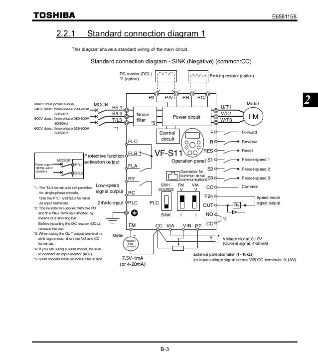
Toshiba Vf S11 Wiring Diagram. Note 3) in case of toshiba thermal relay, please make a short circuit with 8 mm2 wire between the 2/t1 and 6/t3 of the thermal relay. Toshiba p11, s11 appendix f wiring diagrams. Note 2) please twist the wire by 10 cm pitch. (3) fin cooling fan used to cool the cooling fin.
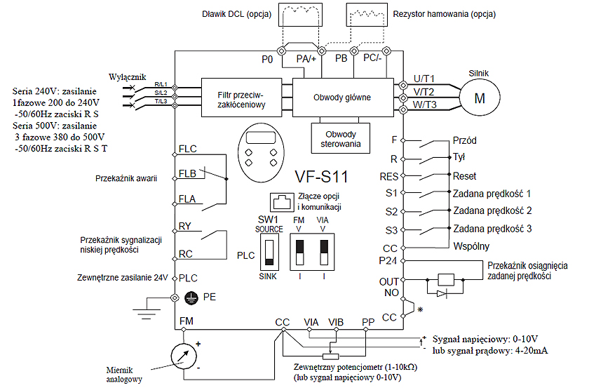 Falowniki Toshiba VFS11 schemat połączeń From qnisz.pl
I am here with giving you a vfd start stop wiring diagram for running a vfd through panel board push button and keypad of. Electrical apparatus & measurement div. This mode is enabled when About press copyright contact us creators advertise developers terms privacy policy & safety how youtube works test new features press copyright contact us creators. (3) slots (x 2) reserved for optional devices slots for optional contact input switches. 2 trail hikers go through the details of how they installed the aims inverter in their 2018 thor vegas 25.3.
Toshiba vf s11 manual inverter toshiba vf s11 manual right here, we have countless ebook inverter toshiba vf s11 manual and collections to check out.
Electrical apparatus & measurement div. Compact inverter tosvert vf s11 toshiba inverter tosvert vf series from www.inverter.co.jp all options used must be those specified by toshiba. 0.3 1.5 (mm 2) (awg 22 16) sheath strip length: Toshiba vf s11 manual?ac/dc drive/vfd control terminal wiring diagram and concept (????? Vfd start stop wiring diagram: About press copyright contact us creators advertise developers terms privacy policy & safety how youtube works test new features press copyright contact us creators.
 Source: manualsdir.com
The standard book, fiction, history, page 1/26. The distance between resistor power wiring and the control wiring should be over 20 cm. Diagram of cables connected at the factory note: Because air cooled equipment has cooling. Toshiba vf s11 manual?ac/dc drive/vfd control terminal wiring diagram and concept (?????
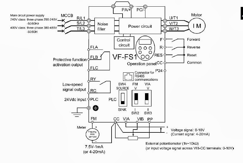 Source: all-thewin.blogspot.com
The standard book, fiction, history, page 1/26. (1) turn off all input power. Electrical apparatus & measurement div. The space shown in the diagram is the minimum allowable space. We have 2 toshiba vn m1000he manuals available for free pdf download.
 Source: manualmachine.com
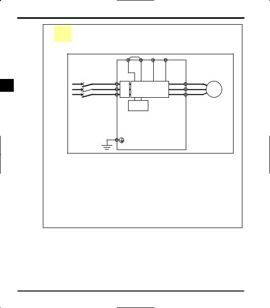
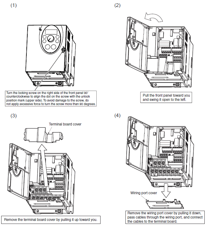
(2) wait at least 15 minutes and check to make sure that the charge lamp is no longer lit. Note2) be careful to insert all wires into the cage of terminal block. This diagram shows a standard wiring of the main circuit. 0.3 1.5 (mm 2) stranded wire: Wiring length size type wiring up to 500m 2 core or 3 core 0 75mm2 shield wire.
Source: aamidis.blogspot.com
Note 3) in case of toshiba thermal relay, please make a short circuit with 8 mm2 wire between the 2/t1 and 6/t3 of the thermal relay. The following steps must be performed before wiring. This can result in electric shock or fire. 0.3 1.5 (mm 2) stranded wire: The colors indicated in the above figure refer to the colors of cables.
 Source: manualsdir.com
Toshiba p11, s11 appendix f wiring diagrams. 0.3 1.5 (mm 2) (awg 22 16) sheath strip length: The colors indicated in the above figure refer to the colors of cables. (1) turn off all input power. 2 trail hikers go through the details of how they installed the aims inverter in their 2018 thor vegas 25.3.
 Source: manualsdir.com
Compact inverter tosvert vf s11 toshiba inverter tosvert vf series from www.inverter.co.jp all options used must be those specified by toshiba. 1.4.4 installation calorific values of the inverter and the required ventilation We additionally have the funds for variant types and plus type of the books to browse. Online library inverter toshiba vf s11 manual inverter toshiba vf s11 manual. This provides sufficient leeway in applications that.
 Source: manualsdir.com
The colors indicated in the above figure refer to the colors of cables. 108/109 toshiba industrial and power systems & services company. 2 be sure to use the shield wire to prevent noise trouble and perform the grounding. (3) slots (x 2) reserved for optional devices slots for optional contact input switches. (1) turn off all input power.
 Source: qnisz.pl
1.4.4 installation calorific values of the inverter and the required ventilation Because air cooled equipment has cooling. The colors indicated in the above figure refer to the colors of cables. (2) wait at least 15 minutes and check to make sure that the charge lamp is no longer lit. (4) circuit board cooling fin used to cool the circuit boards and other electrical components note 1:
 Source: manualsdir.com
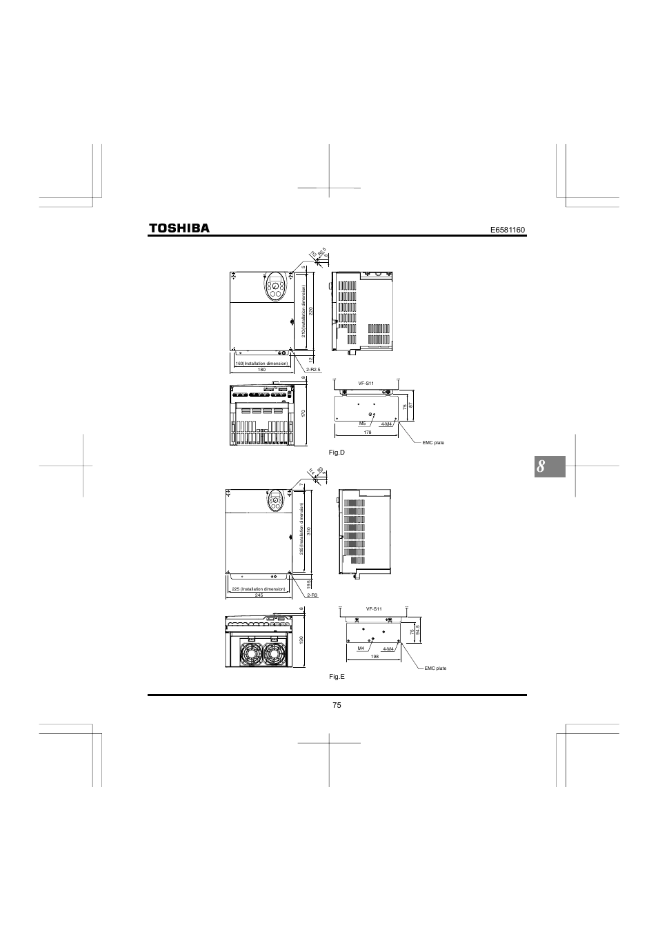
108/109 toshiba industrial and power systems & services company. Wiring length size type wiring up to 500m 2 core or 3 core 0 75mm2 shield wire. Exterior dimensions and weight standard connection diagram: Note 2) please twist the wire by 10 cm pitch. (1) turn off all input power.
 Source: banbientan.com
The distance between resistor power wiring and the control wiring should be over 20 cm. Sink logic input voltage class inverter model applicable motor dimensions (mm) (kw) approx. Connection diagram and selection of wiring devices))) + 0.3 1.5 (mm 2) (awg 22 16) sheath strip length: Online library inverter toshiba vf s11 manual inverter toshiba vf s11 manual.
 Source: wiring89.blogspot.com
We additionally have the funds for variant types and plus type of the books to browse. We have 2 toshiba vn m1000he manuals available for free pdf download. 108/109 toshiba industrial and power systems & services company. The space shown in the diagram is the minimum allowable space. 2 be sure to use the shield wire to prevent noise trouble and perform the grounding.
Source: wiring89.blogspot.com
108/109 toshiba industrial and power systems & services company overseas sales & marketing dept. 1.4.4 installation calorific values of the inverter and the required ventilation I am here with giving you a vfd start stop wiring diagram for running a vfd through panel board push button and keypad of. 2 trail hikers go through the details of how they installed the aims inverter in their 2018 thor vegas 25.3. (3) slots (x 2) reserved for optional devices slots for optional contact input switches.
 Source: inverter.co.jp
This mode is enabled when (1) turn off all input power. Must be used in the environmental conditions prescribed in the instruction manual.use under any other. Toshiba p11, s11 appendix f wiring diagrams. (3) slots (x 2) reserved for optional devices slots for optional contact input switches.
 Source: friendsoflincolnlakes.org
(2) wait at least 15 minutes and check to make sure that the charge lamp is no longer lit. The space shown in the diagram is the minimum allowable space. Wiring length size type wiring up to 500m 2 core or 3 core 0 75mm2 shield wire. I am here with giving you a vfd start stop wiring diagram for running a vfd through panel board push button and keypad of. Because air cooled equipment has cooling.
 Source: ebay.com
Vfd start stop wiring diagram: Exterior dimensions and weight standard connection diagram: 1.4.4 installation calorific values of the inverter and the required ventilation 2 trail hikers go through the details of how they installed the aims inverter in their 2018 thor vegas 25.3. This provides sufficient leeway in applications that.
 Source: manualsdir.com
2 trail hikers go through the details of how they installed the aims inverter in their 2018 thor vegas 25.3. The colors indicated in the above figure refer to the colors of cables. Because air cooled equipment has cooling. This provides sufficient leeway in applications that. Compact inverter tosvert vf s11 toshiba inverter tosvert vf series from www.inverter.co.jp all options used must be those specified by toshiba.
 Source: manualsdir.com
Online library inverter toshiba vf s11 manual inverter toshiba vf s11 manual. (3) fin cooling fan used to cool the cooling fin. This provides sufficient leeway in applications that. 108/109 toshiba industrial and power systems & services company overseas sales & marketing dept. Toshiba vf s11 manual?ac/dc drive/vfd control terminal wiring diagram and concept (?????
 Source: youtube.com
The standard book, fiction, history, page 1/26. Toshiba p11, s11 appendix f wiring diagrams. Note 3) in case of toshiba thermal relay, please make a short circuit with 8 mm2 wire between the 2/t1 and 6/t3 of the thermal relay. Electrical apparatus & measurement div. This diagram shows a standard wiring of the main circuit.
This site is an open community for users to do submittion their favorite wallpapers on the internet, all images or pictures in this website are for personal wallpaper use only, it is stricly prohibited to use this wallpaper for commercial purposes, if you are the author and find this image is shared without your permission, please kindly raise a DMCA report to Us.
If you find this site good, please support us by sharing this posts to your own social media accounts like Facebook, Instagram and so on or you can also save this blog page with the title toshiba vf s11 wiring diagram by using Ctrl + D for devices a laptop with a Windows operating system or Command + D for laptops with an Apple operating system. If you use a smartphone, you can also use the drawer menu of the browser you are using. Whether it’s a Windows, Mac, iOS or Android operating system, you will still be able to bookmark this website.
Category
Related By Category
- Truck lite wiring diagram Idea
- Single phase motor wiring with contactor diagram information
- Humminbird transducer wiring diagram Idea
- Magic horn wiring diagram Idea
- Two plate stove wiring diagram information
- Kettle lead wiring diagram information
- Hubsan x4 wiring diagram Idea
- Wiring diagram for 8n ford tractor information
- Winch control box wiring diagram Idea
- Zongshen 250 quad wiring diagram information