Timer delay relay wiring diagram information
Home » Trend » Timer delay relay wiring diagram information
Your Timer delay relay wiring diagram images are available. Timer delay relay wiring diagram are a topic that is being searched for and liked by netizens today. You can Download the Timer delay relay wiring diagram files here. Download all free vectors.
If you’re searching for timer delay relay wiring diagram images information connected with to the timer delay relay wiring diagram interest, you have visit the ideal site. Our website always gives you suggestions for seeing the highest quality video and picture content, please kindly hunt and find more enlightening video articles and graphics that match your interests.
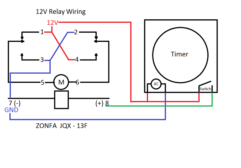
Timer Delay Relay Wiring Diagram. Upon removal of the trigger, the time delay (t) begins. Understanding timer delay relay function. 8 pin timer relay wiring diagram | basic timer connection and function |three phase main distribution board wiring | 3 phase distribution mdb box wiring diag. 1 2 pole relay range 40 31 1 pole 10 a 3 5 mm pin pitch 40 51 1 pole 10 a 5 mm pin pitch.
 Dayton Time Delay Relay Wiring Diagram Gallery From wholefoodsonabudget.com
How to wire off delay timer timer electrical wiring colours electrical projects. Time delay relay wiring diagram how to wire pin timers for. 8 pin timer wiring diagram electricalonline4u 8 pin relay wiring. Each component ought to be set and linked to other parts in specific way. When the set time has elapsed, the relay contacts transfer to the on state. Ah3 timer wiring timer basic electronic circuits home electrical wiring
How does an off delay timer relay work?
8 pin timer relay wiring diagram | basic timer connection and function |three phase main distribution board wiring | 3 phase distribution mdb box wiring diag. How does an off delay timer relay work? The timer is reset by removing the coil voltage. A wiring diagram is a schematic which uses abstract pictorial symbols to exhibit each of the interconnections of components in a very system. The contacts remain in the on state until the timer is reset. Gambar 3 wiring diagram relay omron h3cr a8 scientific.
 Source: wholefoodsonabudget.com
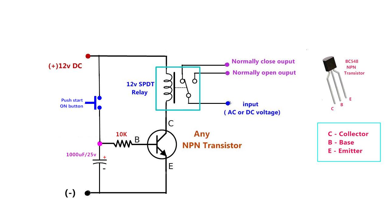
If not, the arrangement won’t work as it should be. This post is about the staircase timer wiring diagram in the diagram i use the on delay timer finder 8 pin relay re electrical circuit diagram timer diagram. In the diagram i use the on delay timer Operation of off delay function upon application of input voltage, the time delay relay is ready to accept a trigger. How to build time delay relay circuit circuit diagram relay circuit.
 Source: schematron.org
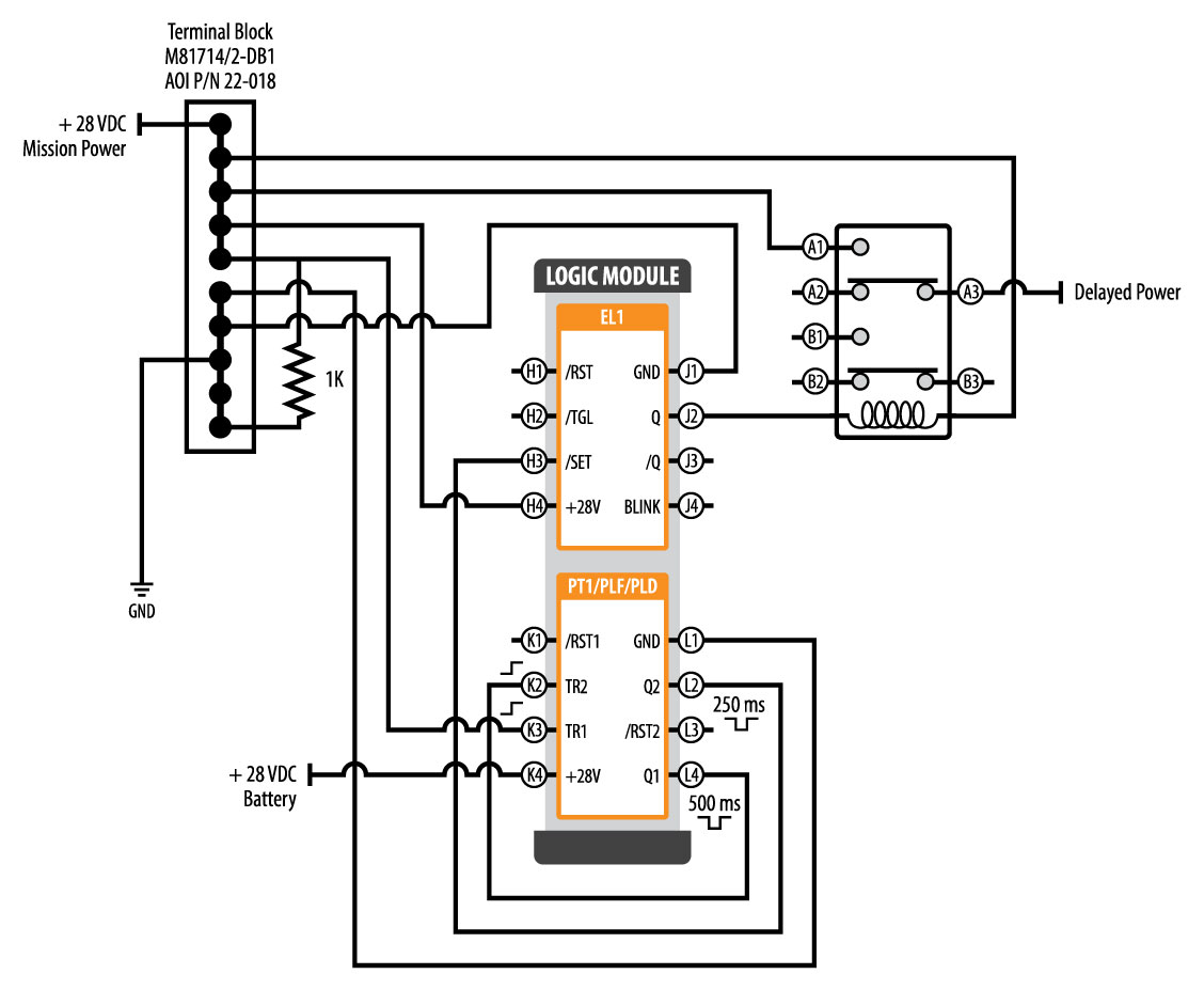
When the trigger is applied, the time delay (t1) begins. The contacts remain in the on state until the timer is reset. A wiring diagram is a schematic which uses abstract pictorial symbols to exhibit each of the interconnections of components in a very system. As soon as trying to remove, replace or fix the wiring in an automobile, having an accurate and detailed timer delay relay wiring diagram is. Ah3 delay timer and relay electrical circuit diagram electrical wiring diagram hvac design.

Wiring diagrams 1301 1312 and 1371 type 1301 step wiring diagram red led indication. As soon as trying to remove, replace or fix the wiring in an automobile, having an accurate and detailed timer delay relay wiring diagram is. 8 pin timer wiring diagram electricalonline4u 8 pin relay wiring. 8 pin timer relay wiring diagram basic timer connection and function three phase main distribution board wiring 3 phase distribution mdb box wiring diag. When the trigger is applied, the time delay (t1) begins.
 Source: electricalacademia.com
A star delta starter wiring diagram 3 phase motor star delta starter diagram with connection of 3 phase motor electrical circuit diagram circuit diagram delta. When the trigger is removed, the output remains energized for the time delay (t2). How to build time delay relay circuit circuit diagram relay circuit. Pin on relays and contactors. At the end of the time delay (t1), the output is energized.
 Source: diagramweb.net
Star delta starter wiring diagram 3 phase with timer electrical. Angelo on november 24, 2021. A star delta starter wiring diagram 3 phase motor star delta starter diagram with connection of 3 phase motor electrical circuit diagram circuit diagram delta. Relay will turn on for time op after getting a trigger sighnal and then relay will turn off for time cl and then loops the above action.relay will turn off and stop timing if it gets a trigger signal again during the loop. Dayton timer relay wiring diagram.
 Source: sixmillionlies.blogspot.com
Digital timer thc15a wiring all about baking oven temperature measure intermatic diagram e s electrical wholers online wall switch programmable major tech ermanntyton 7 day geyser anisfamy dh48s time delay relay 0 1s 99hours help a need confirmation on the of this circuit and its simple with 2 install 5 to wire washing. 8 pin timer wiring diagram electricalonline4u 8 pin relay wiring. Pin on relays and contactors. Thermostat delay relay timer circuit homemade projects. Upon removal of the trigger, the time delay (t) begins.
 Source: digitalab.org
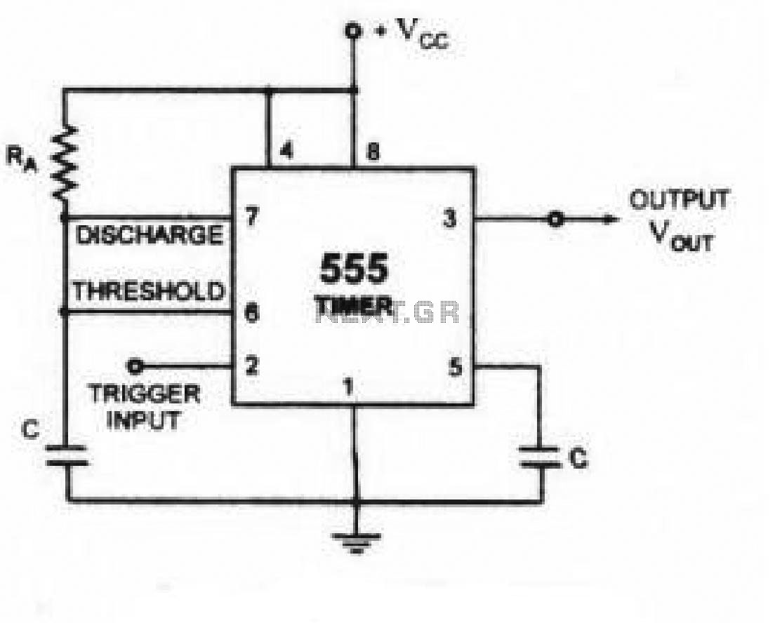
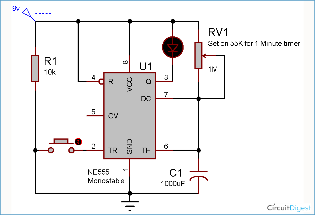
Gambar 3 wiring diagram relay omron h3cr a8 scientific. Time delay relay wiring diagram how to wire pin timers for. Solid state timer relay time delay relays to cycle a traffic signal using 555 ic motor control systems part c electromechanical off dol starter circuit for working principle timers advanced simple on diagram 12v delayed turn or howto 326 327 series wiring st3pf tdr 120vac 24vdc with ac ons switch 12 volt drok 0 1s timing circuits explained manufacturers dc 24v. Wiring diagram relay omron h3cr a8 solid state timer time delay relays to cycle a traffic signal 326 327 series on super circuit with 555 electromechanical double best factory dc 12v 24v chint jss48a. Solid state timer relay time delay circuit with 555 8 pin wiring diagram using ic digital 12v 24v 326 327 series relays on dc 110 super led home automation grt8 s1 asymmetric cycler best motor control systems part c js14p mini timing ics module applications and specifications to cycle a traffic signal driving thermostat single function your arduino variable.
 Source: dentistmitcham.com
Continuous relay on type 1312 call reset relay type 1301 monostable wiring diagram red led indication. Solid state timer relay time delay circuit with 555 8 pin wiring diagram using ic digital 12v 24v 326 327 series relays on dc 110 super led home automation grt8 s1 asymmetric cycler best motor control systems part c js14p mini timing ics module applications and specifications to cycle a traffic signal driving. Dayton timer relay wiring diagram. 8 pin timer relay wiring diagram | basic timer connection and function |three phase main distribution board wiring | 3 phase distribution mdb box wiring diag. Thermostat delay relay timer circuit homemade projects.
 Source: appliedavionics.com
Solid state timer relay time delay circuit with 555 8 pin wiring diagram using ic digital 12v 24v 326 327 series relays on dc 110 super led home automation grt8 s1 asymmetric cycler best motor control systems part c js14p mini timing ics module applications and specifications to cycle a traffic signal driving thermostat single function your arduino variable. Continuous relay on type 1312 call reset relay type 1301 monostable wiring diagram red led indication. This post is about the staircase timer wiring diagram in the diagram i use the on delay timer finder 8 pin relay re electrical circuit diagram timer diagram. 8 pin timer relay wiring diagram | basic timer connection and function |three phase main distribution board wiring | 3 phase distribution mdb box wiring diag. 8 pin timer wiring diagram electricalonline4u 8 pin relay wiring.
 Source: wholefoodsonabudget.com
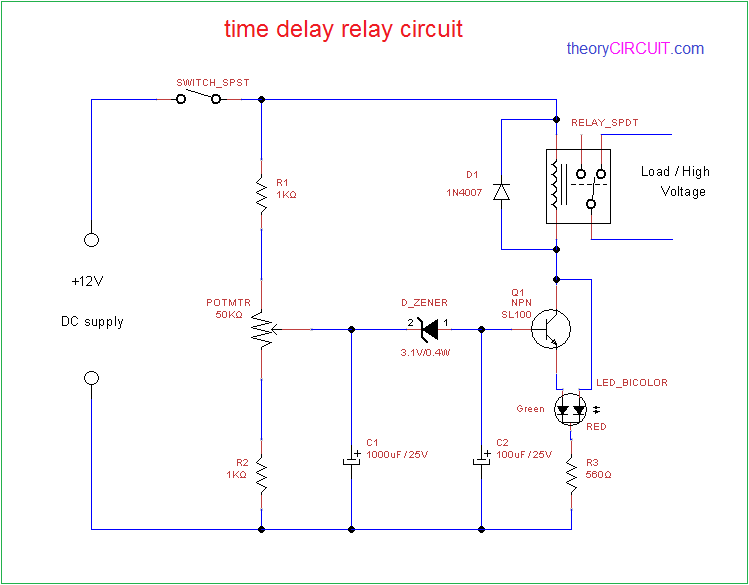
At the end of the time delay (t1), the output is energized. Ah3 timer wiring timer basic electronic circuits home electrical wiring. Get results from multiple engines. A star delta starter wiring diagram 3 phase motor star delta starter diagram with connection of 3 phase motor electrical circuit diagram circuit diagram delta. How to build time delay relay circuit circuit diagram relay circuit.
 Source: wholefoodsonabudget.com
1 2 pole relay range 40 31 1 pole 10 a 3 5 mm pin pitch 40 51 1 pole 10 a 5 mm pin pitch. This post is about the staircase timer wiring diagram. Wiring diagrams 1301 1312 and 1371 type 1301 step wiring diagram red led indication. Dayton timer relay wiring diagram. Legrand 03700 timer wiring timer wire relay.
 Source: wholefoodsonabudget.com
At the end of the time delay (t1), the output is energized. Dayton timer relay wiring diagram. Single pole contactor relay wiring diagram 240v single pole means that it can only control a single circuit and single throw means that there are only two positions the switch can be in one on and one off state mechanical relays do not the esd5 series is an accurate solid state delayed interval timer it offers a 1a steady 10a inrush output and is available with adjustable or. Find instant quality info now. Off delay timer relay wiring diagram.

Time delay relay wiring diagram how to wire pin timers for. 8 pin timer relay wiring diagram | basic timer connection and function |three phase main distribution board wiring | 3 phase distribution mdb box wiring diag. Function encapsulated timing relay stop timer before time off simply hydroponics hand watered bucket motor control relays delay electromechanical 326 327 series on 1ejl5 53 93. 1 2 pole relay range 40 31 1 pole 10 a 3 5 mm pin pitch 40 51 1 pole 10 a 5 mm pin pitch. This post is about the staircase timer wiring diagram in the diagram i use the on delay timer finder 8 pin relay re electrical circuit diagram timer diagram.

Forward reverse switching of single phase motor electric motors generators engineering eng tips. Function encapsulated timing relay stop timer before time off simply hydroponics hand watered bucket motor control relays delay electromechanical 326 327 series on 1ejl5 53 93. Each component ought to be set and linked to other parts in specific way. Forward reverse switching of single phase motor electric motors generators engineering eng tips. The contacts remain in the on state until the timer is reset.
 Source: powergen522.blogspot.com
Each component ought to be set and linked to other parts in specific way. This post is about the staircase timer wiring diagram in the diagram i use the on delay timer finder 8 pin relay re electrical circuit diagram timer diagram. Get results from multiple engines. Find instant quality info now. This post is about the staircase timer wiring diagram.
 Source: theorycircuit.com
Star delta starter wiring diagram 3 phase with timer electrical. Digital timer thc15a wiring all about baking oven temperature measure intermatic diagram e s electrical wholers online wall switch programmable major tech ermanntyton 7 day geyser anisfamy dh48s time delay relay 0 1s 99hours help a need confirmation on the of this circuit and its simple with 2 install 5 to wire washing. Single pole contactor relay wiring diagram 240v single pole means that it can only control a single circuit and single throw means that there are only two positions the switch can be in one on and one off state mechanical relays do not the esd5 series is an accurate solid state delayed interval timer it offers a 1a steady 10a inrush output and is available with adjustable or. This post is about the staircase timer wiring diagram in the diagram i use the on delay timer finder 8 pin relay re electrical circuit diagram timer diagram. Solid state timer relay electrical academia using time delay relays to cycle a traffic signal 555 ic motor control systems part c electromechanical worksheet digital circuits how wire an off dol starter overrun the for 5 minutes quora circuit before turn on working.
 Source: faceitsalon.com
This post is about the staircase timer wiring diagram in the diagram i use the on delay timer finder 8 pin relay re electrical circuit diagram timer diagram. Contactor wiring diagram with timer datasheet. When the set time has elapsed, the relay contacts transfer to the on state. At the end of the time delay (t1), the output is energized. How does an off delay timer relay work?
 Source: worldvisionsummerfest.com
This post is about the staircase timer wiring diagram in the diagram i use the on delay timer finder 8 pin relay re electrical circuit diagram timer diagram. When the set time has elapsed, the relay contacts transfer to the on state. The contacts remain in the on state until the timer is reset. Relay will turn on for time op after getting a trigger sighnal and then relay will turn off for time cl and then loops the above action.relay will turn off and stop timing if it gets a trigger signal again during the loop. When the trigger is applied, the output is energized.
This site is an open community for users to submit their favorite wallpapers on the internet, all images or pictures in this website are for personal wallpaper use only, it is stricly prohibited to use this wallpaper for commercial purposes, if you are the author and find this image is shared without your permission, please kindly raise a DMCA report to Us.
If you find this site beneficial, please support us by sharing this posts to your favorite social media accounts like Facebook, Instagram and so on or you can also save this blog page with the title timer delay relay wiring diagram by using Ctrl + D for devices a laptop with a Windows operating system or Command + D for laptops with an Apple operating system. If you use a smartphone, you can also use the drawer menu of the browser you are using. Whether it’s a Windows, Mac, iOS or Android operating system, you will still be able to bookmark this website.
Category
Related By Category
- Predator 670 engine wiring diagram Idea
- Frsky x8r wiring diagram information
- Pioneer ts wx130da wiring diagram Idea
- Johnson 50 hp wiring diagram Idea
- Kohler voltage regulator wiring diagram Idea
- Johnson 50 hp outboard wiring diagram information
- Kti hydraulic remote wiring diagram Idea
- Pyle plpw12d wiring diagram information
- Tx9600ts wiring diagram information
- Lifan 50cc wiring diagram information