Time delay relay wiring diagram Idea
Home » Trending » Time delay relay wiring diagram Idea
Your Time delay relay wiring diagram images are available. Time delay relay wiring diagram are a topic that is being searched for and liked by netizens today. You can Get the Time delay relay wiring diagram files here. Get all royalty-free vectors.
If you’re looking for time delay relay wiring diagram pictures information related to the time delay relay wiring diagram interest, you have pay a visit to the ideal site. Our website always gives you hints for viewing the highest quality video and picture content, please kindly search and find more informative video content and graphics that match your interests.
Time Delay Relay Wiring Diagram. It reveals the elements of the circuit as streamlined shapes as well as the power and signal links in between the tools. Contact (applying voltage to the pins could damage the. The kh1 series adjustable on delay module connection diagram. Air handler fan relay wiring diagram.
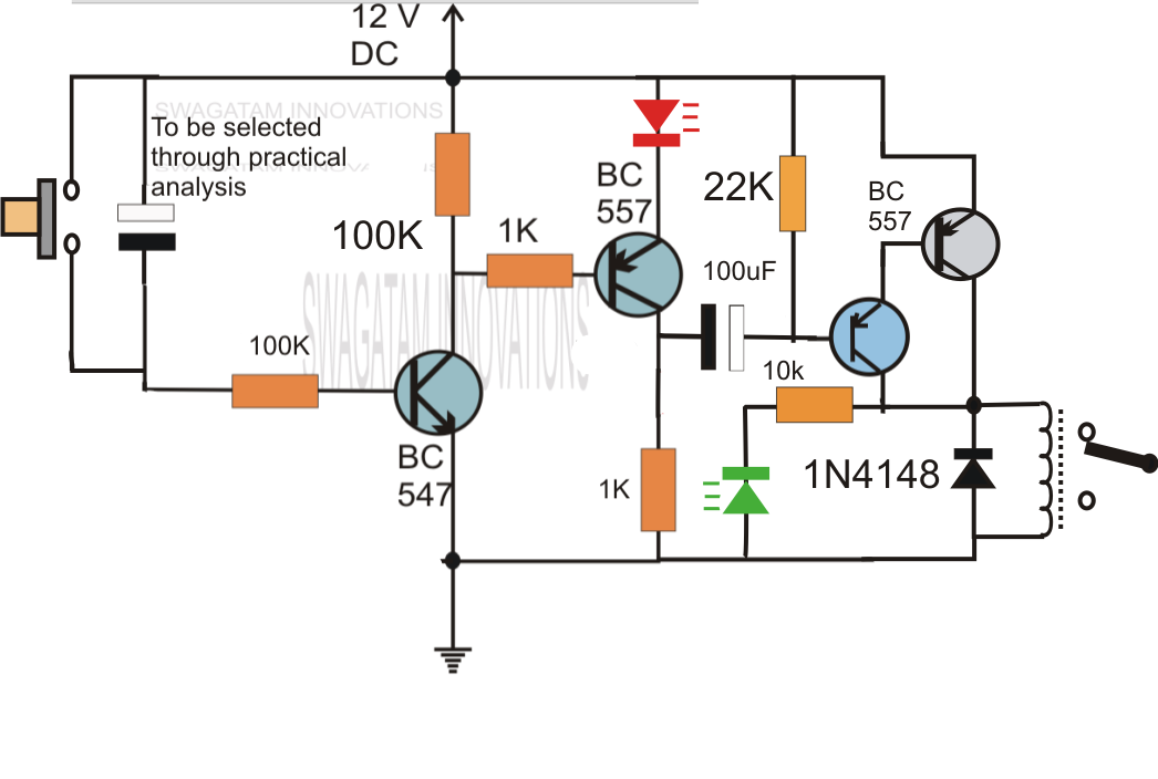 Simple Delay Timer Circuits Explained From homemade-circuits.com
A relay is typically used to control a component that draws high amperage. Time delay is variable and dependent on the resistance value of rt. For triggered dc input voltages, make sure the polarity matches the connection diagram. Find instant quality info now. Air handler fan relay wiring diagram. The relay has normally open and normally close contact.
For triggered dc input voltages, make sure the polarity matches the connection diagram.
There’ll be main lines which are represented by l1, l2, l3, and so on. Replacing time delay relay and checking operation. This post is about the staircase timer wiring diagram in the diagram i use the on delay timer finder 8 pin relay re electrical circuit diagram timer diagram. For triggered dc input voltages, make sure the polarity matches the connection diagram. However, it does not imply link between the wires. At times, the wires will cross.
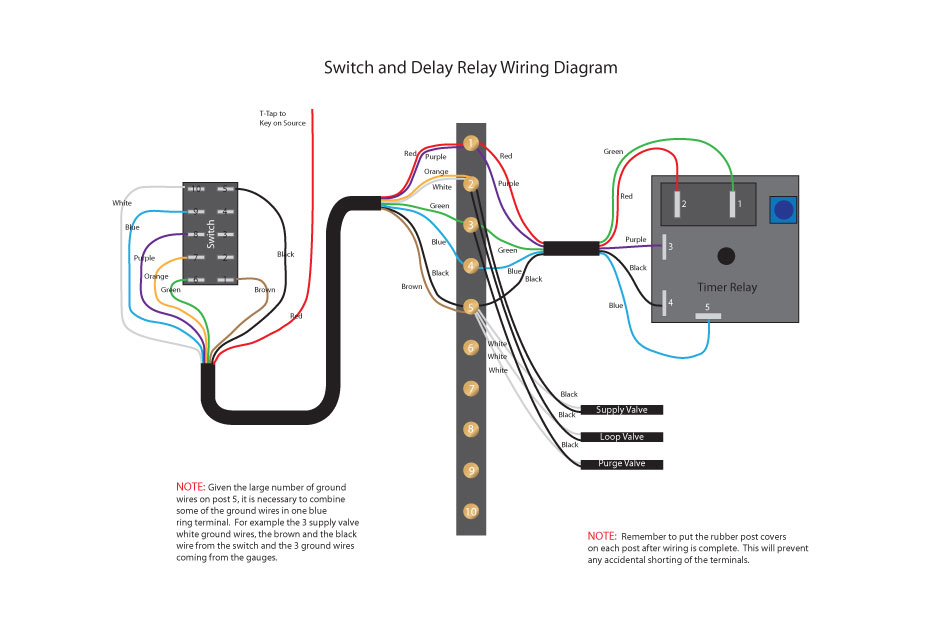 Source: sandhillstudios.com
A beginner’s guide to circuit diagrams A relay is typically used to control a component that draws high amperage. For triggered dc input voltages, make sure the polarity matches the connection diagram. Wiring diagram air handler fan relay wiring diagram. For products that use a control.
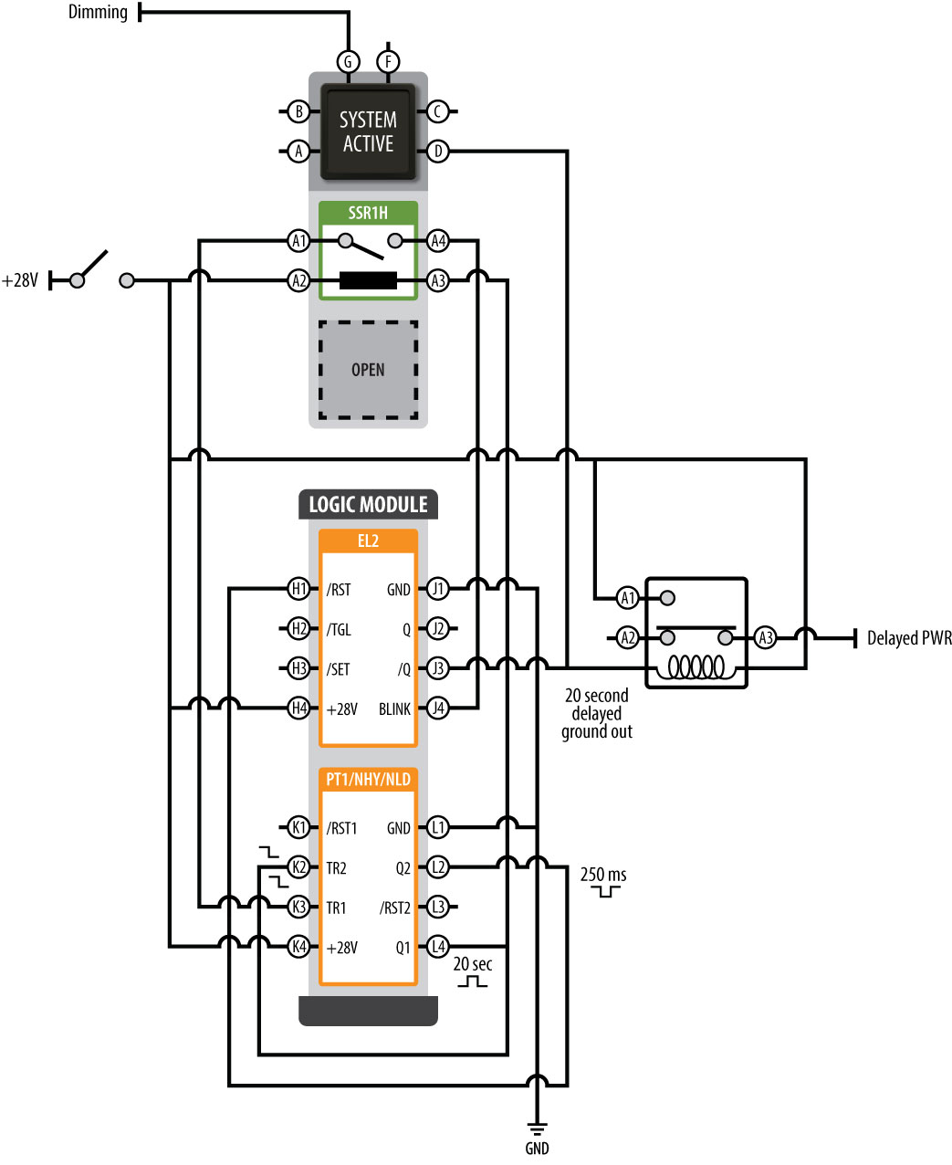 Source: radiowiring.blogspot.com
Wiring diagram air handler fan relay wiring diagram. This post is about the staircase timer wiring diagram in the diagram i use the on delay timer finder 8 pin relay re electrical circuit diagram timer diagram. Module load at pin 2 is a relay coil. At times, the wires will cross. Replacing time delay relay and checking operation.
Source: relays.struthers-dunn.com
Gambar 3 wiring diagram relay omron h3cr a8 scientific. Adjusting the delay time is often as simple as turning a knob. To be wired inaccordance with n.e.c.and local codes. Use copper wire (75ºc min) only between disconnect switch and unit. Voltage, the time delay relay is ready to accept a trigger.
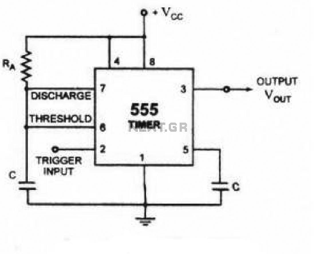 Source: schematron.org
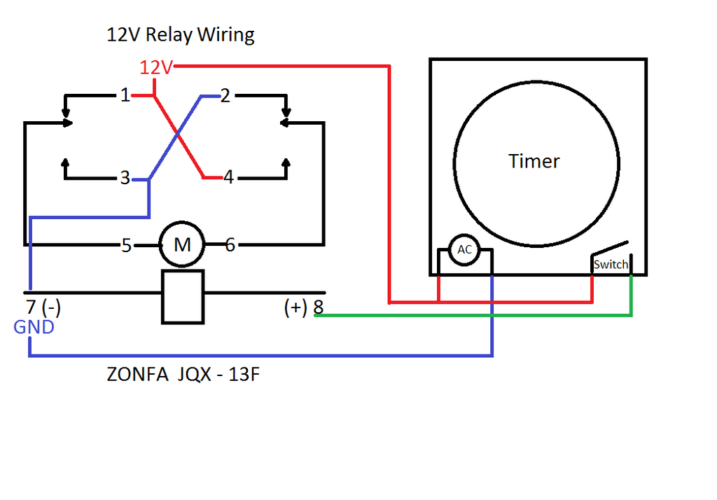
View is from the flat side with the catalog numbers. There’ll be main lines which are represented by l1, l2, l3, and so on. The relay has normally open and normally close contact. Their purpose is to control an event based on time. Wiring diagram relay omron h3cr a8 solid state timer time delay relays to cycle a traffic signal 326 327 series on super circuit with 555 electromechanical double best factory dc 12v 24v chint jss48a.
 Source: ricardolevinsmorales.com
Wiring diagram for time delay relay wiring diagram line wiring diagram wiring diagram line we are make source the schematics, wiring diagrams and technical photos Below you can find the pin diagram of 555 timer ic along with the details of each pin. A relay is typically used to control a component that draws high amperage. This pin should be connected to ground. Find instant quality info now.
 Source: dentistmitcham.com
Wire the socket per the wiring diagram on the side of the. Off delay timer relay wiring diagram. To be wired inaccordance with n.e.c.and local codes. A beginner’s guide to circuit diagrams Use 60amp class k fuses only,.
 Source: 2020cadillac.com
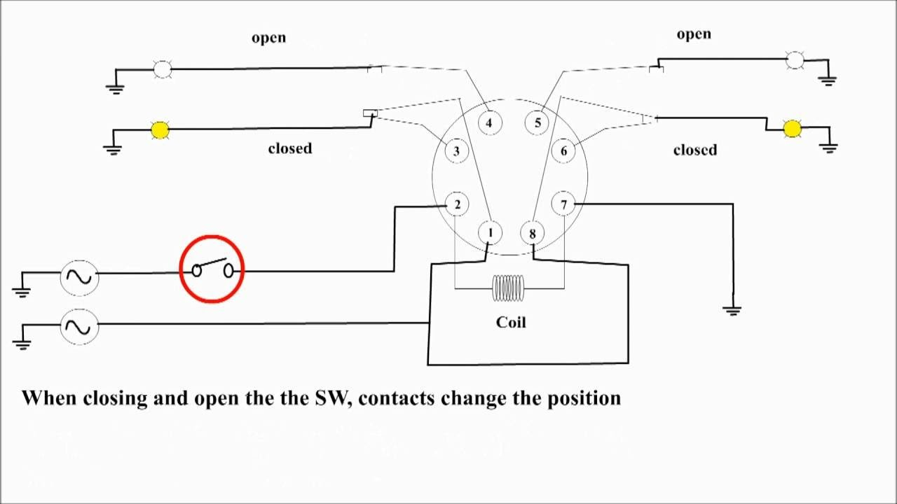
Contact (applying voltage to the pins could damage the. The kh1 series adjustable on delay module connection diagram. The comparator two output is connected to set pin of. The time delay relay circuit described here is intended for this purpose. Capacitor c1 charges through r1 and vr.
 Source: faceitsalon.com
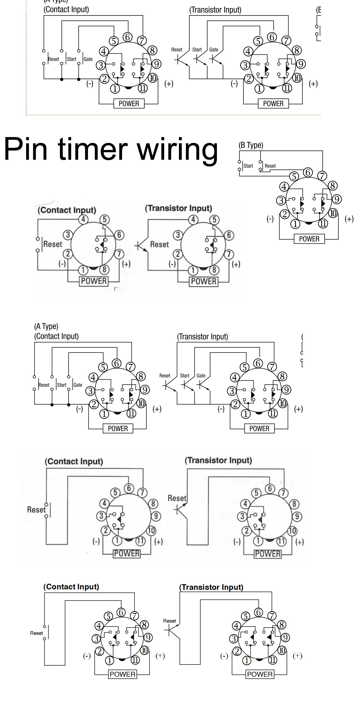
Before going into detail of time delay circuit, first we need to learn about 555 timer ic first. Injunction of 2 wires is generally indicated by black dot in the junction of two lines. The difference between relays and time delay relays is when the output contacts open & close: To be wired inaccordance with n.e.c.and local codes. Rt @ 0 ohm = minimum delay, rt @ 1m ohm = maximum delay.
 Source: 3.ncceconnect.org
Time delay is variable and dependent on the resistance value of rt. The comparator two output is connected to set pin of. It gives power to the device only after one to two minutes of delay after the power is switched on. Find instant quality info now. The relay allows full power to the component without needing a switch that can carry the amps.
 Source: galvinconanstuart.blogspot.com
Get results from multiple engines. This pin should be connected to ground. There’ll be main lines which are represented by l1, l2, l3, and so on. Find instant quality info now. It shows the components of the circuit as simplified shapes, and the gift and signal contacts along with the devices.
Source: bosco-mylove.blogspot.com
Adjusting the delay time is often as simple as turning a knob. Before you wire a 230v air compressor you should always check the manual for the proper wire gauge. Their purpose is to control an event based on time. Use 60amp class k fuses only,. Wiring diagram air handler fan relay wiring diagram.
Source: radiowiring.blogspot.com
On time delay relays, the contacts can open or. Wiring diagram air handler fan relay wiring diagram. For products that use a control. At times, the wires will cross. Adjusting the delay time is often as simple as turning a knob.
 Source: wholefoodsonabudget.com
Application requirements for time delay relays (tdrs) david bredhold. Rly02807 relay as they were on the rly02257 relay. Below you can find the pin diagram of 555 timer ic along with the details of each pin. It shows the components of the circuit as simplified shapes, and the gift and signal contacts along with the devices. At times, the wires will cross.
 Source: sixmillionlies.blogspot.com
Time delay relays are simply control relays with a time delay built in. Air handler fan relay wiring diagram. Replacing time delay relay and checking operation. Make sure to remove s5 jumper. It gives power to the device only after one to two minutes of delay after the power is switched on.
 Source: diagramweb.net
Application requirements for time delay relays (tdrs) david bredhold. The comparator two output is connected to set pin of. Make sure to remove s5 jumper. Before going into detail of time delay circuit, first we need to learn about 555 timer ic first. I suggest you try with low voltage first, for example, using the same battery (9v) to control a dc lamp or a led with 560 ohm resistor in.
 Source: diagramweb.net
At times, the wires will cross. Gambar 3 wiring diagram relay omron h3cr a8 scientific. The comparator two output is connected to set pin of. When the trigger is applied, the time delay (t1) begins. Wiring diagram air handler fan relay wiring diagram.
 Source: homemade-circuits.com
For products that use a control. Crimp one of the red female spade.relay wiring diagram. Wire the socket per the wiring diagram on the side of the. Gambar 3 wiring diagram relay omron h3cr a8 scientific. Find instant quality info now.
 Source: wholefoodsonabudget.com
Use copper wire (75ºc min) only between disconnect switch and unit. Note that the user must provide the voltage to power the load being switched by the output contacts of the time delay relay. Trigger pin is dragged from the negative input of comparator two. At times, the wires will cross. Time delay relays are simply control relays with a time delay built in.
This site is an open community for users to submit their favorite wallpapers on the internet, all images or pictures in this website are for personal wallpaper use only, it is stricly prohibited to use this wallpaper for commercial purposes, if you are the author and find this image is shared without your permission, please kindly raise a DMCA report to Us.
If you find this site serviceableness, please support us by sharing this posts to your favorite social media accounts like Facebook, Instagram and so on or you can also save this blog page with the title time delay relay wiring diagram by using Ctrl + D for devices a laptop with a Windows operating system or Command + D for laptops with an Apple operating system. If you use a smartphone, you can also use the drawer menu of the browser you are using. Whether it’s a Windows, Mac, iOS or Android operating system, you will still be able to bookmark this website.
Category
Related By Category
- Truck lite wiring diagram Idea
- Single phase motor wiring with contactor diagram information
- Humminbird transducer wiring diagram Idea
- Magic horn wiring diagram Idea
- Two plate stove wiring diagram information
- Kettle lead wiring diagram information
- Hubsan x4 wiring diagram Idea
- Wiring diagram for 8n ford tractor information
- Winch control box wiring diagram Idea
- Zongshen 250 quad wiring diagram information