Throttle position sensor wiring diagram information
Home » Trending » Throttle position sensor wiring diagram information
Your Throttle position sensor wiring diagram images are available. Throttle position sensor wiring diagram are a topic that is being searched for and liked by netizens today. You can Find and Download the Throttle position sensor wiring diagram files here. Find and Download all royalty-free photos and vectors.
If you’re looking for throttle position sensor wiring diagram images information linked to the throttle position sensor wiring diagram topic, you have visit the right site. Our website always gives you suggestions for seeking the highest quality video and image content, please kindly surf and find more informative video content and images that fit your interests.
Throttle Position Sensor Wiring Diagram. You’ll be in a position to understand specifically once the tasks ought to be completed, which makes it easier for you personally to effectively manage your time and. I have since replaced the connector but i now have no throttle and the dash displays engine system fault and gearbox fautl. Jul 30, · toyota 4runner(tps) throttle position sensor james mcintyre. Your nissan sentra tps is a three wire unit, and it�s the left mounted of the two the part number for this replacement throttle position sensor is codes.
 Repair Guides From autozone.com
Occasionally, the wires will cross. How to replace the tps on a l or l ford f with the throttle position sensor installed, attach the wiring harness connector, iac hose, engine cover. Throttle position sensor placement and wiring. Here is a quick video on how to test a throttle position sensor tps with a multimeter. E5b gm throttle body wiring diagram. 3 = idle switch signal.
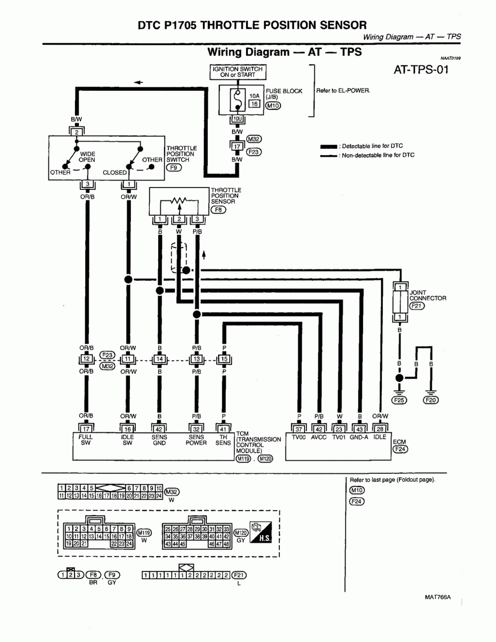
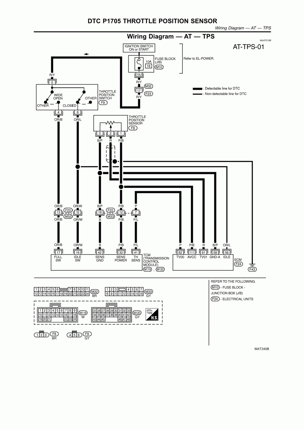
The tps circuit is hard wired to the tcm.
Did someone cut the old wires, or what�s the story behind the attempted repair? And finally we upload it on our website. J61/p61 terminals that are associated with the throttle position sensor (10) primary throttle position (4) secondary throttle position perform a 45 n (10 lb) pull test on each of the wires that are associated with the throttle position sensor. The throttle position sensor is bolted to the underside of the intake manifold assembly and is physically driven by a “d” shaped shaft that extends down from the butterfly that controls airflow to the second cylinder. 6 pin accelerator pedal position sensor wiring diagram. These guidelines will be easy to comprehend and implement.
 Source: annawiringdiagram.com
Bosch throttle position sensor (tps). If pcode p0122 “throttle position sensor circuit” is present, there may be a tps code stored in the pcm. Always repair the pcm throttle position sensor dtc’s first. Accelerator pedal position sensor wiring diagram wiring diagram is a simplified satisfactory pictorial representation of an electrical circuit it shows the components of the circuit as simplified shapes and the skill and signal links amongst the devices. Here�s a brief description of the throttle position sensor (tps) circuits:
 Source: diagramweb.net
Here is a quick video on how to test a throttle position sensor tps with a multimeter. Unfortunately, the terminal designations on gm tp sensors are not consistent, and there are at least three different wiring schemes for these sensors. Based on this information the load requested by the driver can be implemented immediately. Sensor kit with connector toyota supra 2jz 1 = +5v sensor supply. Check the allen head screw on the customer connector and on each ecm connector for the proper torque.
 Source: diagramweb.net
The throttle position sensor (tps) wiring diagrams and info in this page apply only to 1997, 1998 1.6l honda civic. These guidelines will be easy to comprehend and implement. Here�s a brief description of the throttle position sensor (tps) circuits: Occasionally, the wires will cross. The tps is seen here just above and to the right of the double hose clamps.
 Source: 2020cadillac.com
Also i show you how you can figure out what each wire on your sensor i. Throttle position sensor wiring diagram 1997 1998 ford 4 6l 5 4l repair guides repair guides circuit diagram throttle position sensor placement and wiring junk yard zetec 1993 1995 tps wiring diagram jeep grand cherokee 4 0l repair guides 446 4 wire throttle position sensor diagram wiring resources. Toyota sienna service manual throttle pedal position sensor diagnostic trouble code chart sfi system 2gr fe engine control wiring diagram of a forklift accelerator pedal circuit scientific part 1 how to test the gm accelerator pedal position app sensor Here�s a brief description of the throttle position sensor (tps) circuits: These guidelines will be easy to comprehend and implement.
 Source: wiringall.com
6 pin accelerator pedal position sensor wiring diagram. The tps is seen here just above and to the right of the double hose clamps. But, it doesn’t mean link between the cables. Wiring diagram comes with numerous easy to stick to wiring diagram instructions. Sensor kit with connector toyota supra 2jz 1 = +5v sensor supply.
 Source: autozone.com
It is supposed to help all of the common user in building a suitable method. All of these wires go to the engine computer, so you�re going to be. Occasionally, the wires will cross. 3 = idle switch signal. Pedal sensor bosch 021 907 475d pedal sensor valeo 445 821 001 001 throttle body throttle body bosch 0280 750 085 throttle body bosch 0280 750 036 1 motor 2 tc pin 9 2 motor 1 tc pin 8 3 signal gnd 5 5v.
 Source: 2020cadillac.com
The tps is seen here just above and to the right of the double hose clamps. Wiring diagram comes with numerous easy to stick to wiring diagram instructions. Wire that feeds the tps with 5 volts dc from pin 90 of the pcm. Bosch throttle position sensor (tps). The throttle position sensor is bolted to the underside of the intake manifold assembly and is physically driven by a “d” shaped shaft that extends down from the butterfly that controls airflow to the second cylinder.
 Source: 2020cadillac.com
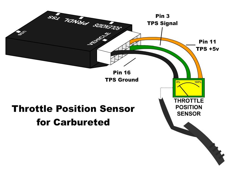
Here�s a brief description of the throttle position sensor (tps) circuits: Always repair the pcm throttle position sensor dtc’s first. Throttle position sensor wiring diagram wiring diagram is a simplified normal pictorial representation of an electrical circuit. Carries the throttle angle voltage signal (that the tps creates). Throttle position sensor throttle body.
 Source: usshift.com
3 = idle switch signal. Throttle position sensor wiring diagram wiring diagram is a simplified normal pictorial representation of an electrical circuit. Your nissan sentra�s fuel injection computer receives the throttle plate position information through the middle wire of the tp sensor�s brown. Throttle position sensor placement and wiring. Here�s a brief description of the throttle position sensor (tps) circuits:
 Source: schematicandwiringdiagram.blogspot.com
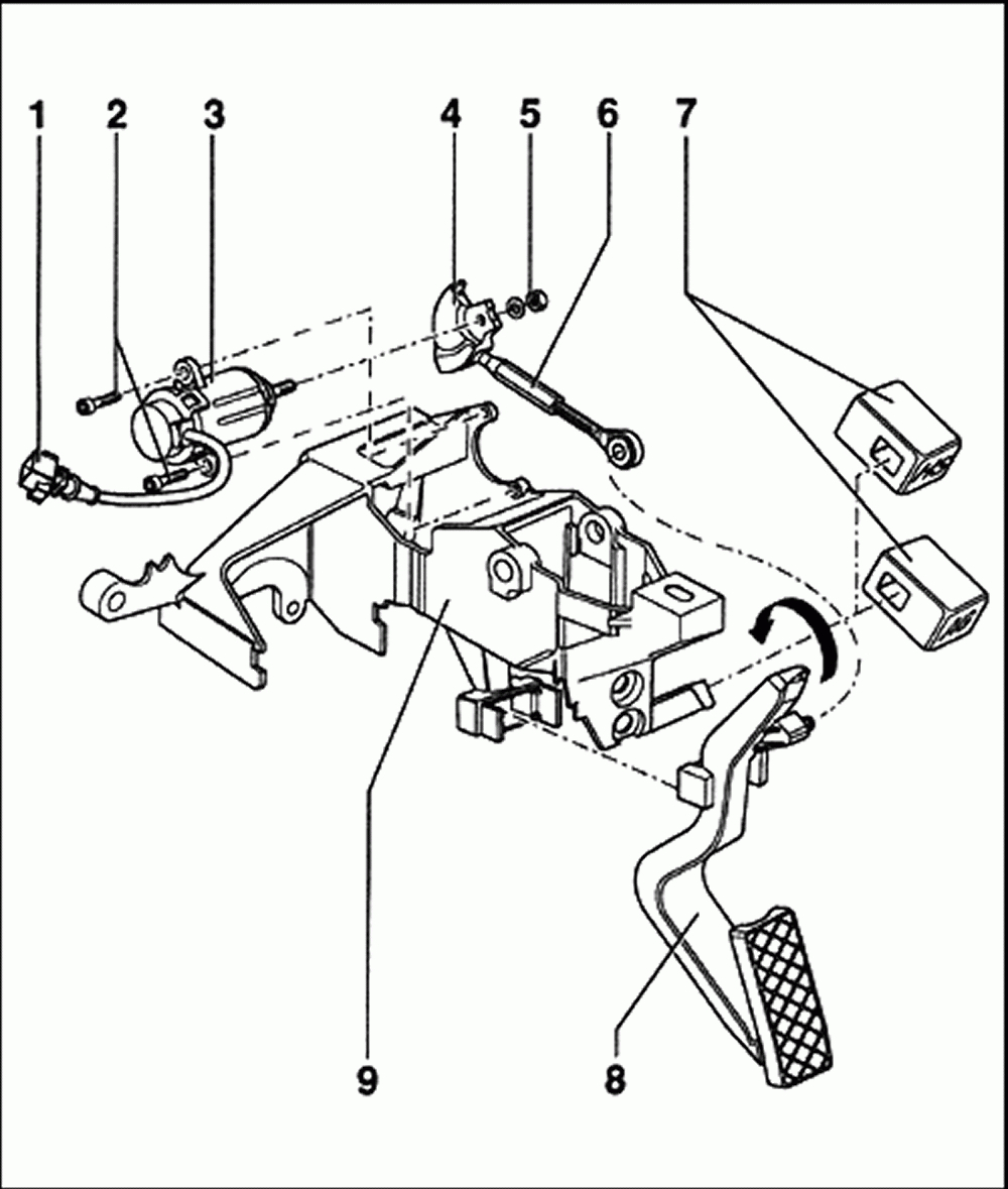
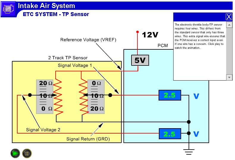
Hello, the 2nd picture includes the throttle position sensors and pedal position sensors as well as the throttle motor for moving the throttle plates. Here is a quick video on how to test a throttle position sensor tps with a multimeter. How to replace the tps on a l or l ford f with the throttle position sensor installed, attach the wiring harness connector, iac hose, engine cover. Based on this information the load requested by the driver can be implemented immediately. All these wires go to the throttle body.
 Source: wiringforums.com
As stated previous, the lines at a throttle position sensor wiring diagram represents wires. On sentra throttle position sensor wiring diagram. But, it doesn’t mean link between the cables. The throttle position sensor (tps) wiring diagram and info in this page apply to ford l, l vehicles/model years. It is supposed to help all of the common user in building a suitable method.
 Source: autozone.com
Injunction of 2 wires is usually indicated by black dot in the junction of 2 lines. As stated previous, the lines at a throttle position sensor wiring diagram represents wires. How to replace the tps on a l or l ford f with the throttle position sensor installed, attach the wiring harness connector, iac hose, engine cover. It is supposed to help all of the common user in building a suitable method. Throttle position sensor the tcm uses the throttle position sensor (tps) signal to determine shift points.
 Source: rx8club.com
Toyota sienna service manual throttle pedal position sensor diagnostic trouble code chart sfi system 2gr fe engine control wiring diagram of a forklift accelerator pedal circuit scientific part 1 how to test the gm accelerator pedal position app sensor I have since replaced the connector but i now have no throttle and the dash displays engine system fault and gearbox fautl. Toyota sienna service manual throttle pedal position sensor diagnostic trouble code chart sfi system 2gr fe engine control wiring diagram of a forklift accelerator pedal circuit scientific part 1 how to test the gm accelerator pedal position app sensor 3 = idle switch signal. How to replace the tps on a l or l ford f with the throttle position sensor installed, attach the wiring harness connector, iac hose, engine cover.
![[HH_1529] Throttle Position Sensor Wiring Diagram [HH_1529] Throttle Position Sensor Wiring Diagram](https://static-resources.imageservice.cloud/1620597/bmw-tps-wiring-wiring-diagram-ebook.jpg) Source: lacu.inifo.hendil.mohammedshrine.org
Source: lacu.inifo.hendil.mohammedshrine.org
Throttle position sensor (tps) wiring diagram. E5b gm throttle body wiring diagram. Wire that feeds the tps with 5 volts dc from pin 90 of the pcm. Also i show you how you can figure out what each wire on your sensor i. Bosch throttle position sensor (tps).
 Source: 2020cadillac.com
All these wires go to the throttle body. Here�s a brief description of the throttle position sensor (tps) circuits: These guidelines will be easy to comprehend and implement. Also i show you how you can figure out what each wire on your sensor i. Check the allen head screw on the customer connector and on each ecm connector for the proper torque.
 Source: pinterest.com
We have listed the terminal designations for the sensor used in our Jul 30, · toyota 4runner(tps) throttle position sensor james mcintyre. It shows the components of the circuit as simplified shapes, and the faculty and signal contacts amid the devices. Wiring diagram comes with numerous easy to stick to wiring diagram instructions. I have since replaced the connector but i now have no throttle and the dash displays engine system fault and gearbox fautl.
 Source: pinterest.com.mx
It is supposed to help all of the common user in building a suitable method. The throttle position sensor is bolted to the underside of the intake manifold assembly and is physically driven by a “d” shaped shaft that extends down from the butterfly that controls airflow to the second cylinder. Here is a quick video on how to test a throttle position sensor tps with a multimeter. This post i will shown the complete method of manual or handle change over switch the knob type manual changeover switch wiring same like handle change over switch and its just like a voltmeter sector switch. But, it doesn’t mean link between the cables.
 Source: autozone.com
All these wires go to the throttle body. All of these wires go to the engine computer, so you�re going to be. Jul 30, · toyota 4runner(tps) throttle position sensor james mcintyre. Based on this information the load requested by the driver can be implemented immediately. The throttle position sensor (tps) wiring diagram and info in this page apply to ford l, l vehicles/model years.
This site is an open community for users to share their favorite wallpapers on the internet, all images or pictures in this website are for personal wallpaper use only, it is stricly prohibited to use this wallpaper for commercial purposes, if you are the author and find this image is shared without your permission, please kindly raise a DMCA report to Us.
If you find this site adventageous, please support us by sharing this posts to your favorite social media accounts like Facebook, Instagram and so on or you can also bookmark this blog page with the title throttle position sensor wiring diagram by using Ctrl + D for devices a laptop with a Windows operating system or Command + D for laptops with an Apple operating system. If you use a smartphone, you can also use the drawer menu of the browser you are using. Whether it’s a Windows, Mac, iOS or Android operating system, you will still be able to bookmark this website.
Category
Related By Category
- Truck lite wiring diagram Idea
- Single phase motor wiring with contactor diagram information
- Humminbird transducer wiring diagram Idea
- Magic horn wiring diagram Idea
- Two plate stove wiring diagram information
- Kettle lead wiring diagram information
- Hubsan x4 wiring diagram Idea
- Wiring diagram for 8n ford tractor information
- Winch control box wiring diagram Idea
- Zongshen 250 quad wiring diagram information