Three phase submersible pump wiring diagram information
Home » Trend » Three phase submersible pump wiring diagram information
Your Three phase submersible pump wiring diagram images are available. Three phase submersible pump wiring diagram are a topic that is being searched for and liked by netizens now. You can Get the Three phase submersible pump wiring diagram files here. Find and Download all royalty-free photos and vectors.
If you’re searching for three phase submersible pump wiring diagram images information related to the three phase submersible pump wiring diagram keyword, you have visit the ideal blog. Our website always gives you suggestions for downloading the highest quality video and image content, please kindly hunt and find more informative video content and images that match your interests.
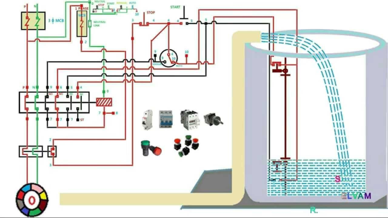
Three Phase Submersible Pump Wiring Diagram. Submersible pump control box wiring diagram for 3 wire single phase. There are just two things that will be found in any 3 wire submersible pump wiring diagram. 3 wire float switch wiring diagram.wiring diagram includes many detailed illustrations that display the relationship of various items. 3 hp single phase submersible pump starter 220 440 v id.
 Submersible Well Pump Wiring Diagram Wiring Diagram From annawiringdiagram.com
A wiring diagram is a streamlined standard pictorial depiction of an electric circuit. Direct on line dol wiring diagram for 3 phase with 110 230vac control circuit electrical circuit diagram circuit diagram electrical wiring diagram. 3 wire submersible well wiring diagram get free circuit diagram electrical circuit diagram capacitors. Ad get 3 submersible pump. Wiring diagram of control panel box of submersible water pump wiring diagram line wiring diagram. Wiring diagrams 22 23 typical wiring a diagrams 3 1 2 5 36 97 3 4 31 42 1 l1 t1 t2 t3 2 l2 3 start hand/off/auto to pump motor ground level control ground pressure switch lower upper electrode to fused disconnect or circuit breaker 3ø furnas pumping panel line load line load 3 phase starter input power (as required by.
Direct on line dol wiring diagram for 3 phase with 110 230vac control circuit electrical circuit diagram circuit diagram electrical wiring diagram.
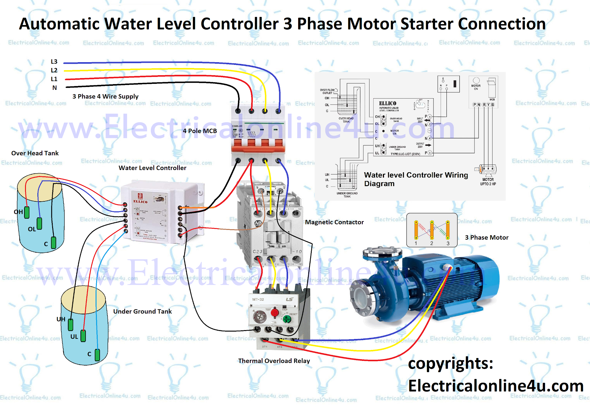
A circuit is usually composed by several components. It consists of directions and diagrams for different types of wiring techniques as well as other items like lights, windows, and so forth. Submersible pump control box wiring diagram for 3 wire single phase. Wiring diagram line we are make source the schematics, wiring diagrams and technical photos. In the diagram, i showed the 3 pole mccb breaker, magnetic contactor, thermal overload protection relay, and normally open, normally close push button switches. There are just two things that will be found in any 3 wire submersible pump wiring diagram.
 Source: dentistmitcham.com
The relay allows minor imbalance in voltage conditions in the three phases within the limits motors are designed to withstand. It makes the procedure for assembling circuit easier. Protection against unbalanced voltage : It really is supposed to assist each of the average user in creating a proper method. Submersible pump control box wiring diagram for 3 wire single phase.
 Source: afzanituall.blogspot.com
Phase submersible pump wiring diagram water troubleshooting grundfos sl series diagrams pdf single motors and controls solar inverter circuit well installation control panel for molock three duplex demand wd3p 4 motor star delta starter seg float switch box cb1269 cb1274 using vlt aqua drive in 3phase 1hp help project winding l t types list 2021 operation manual. Submersible pump control box wiring diagram for 3 wire single phase. Three phase wiring diagram for house wiring diagram line wiring diagram. However, the diagram is a simplified version of this structure. Submersible pump microcontroller wiring diagram three phase electric power png 1000x648px circuit breaker submersible pump panel 3 phase control manufacturer from ahmedabad sim a three phase simplex pump control panel see water inc
 Source: pinterest.com
3 phase submersible pump wiring diagram with dol stater submersible pump submersible pumps R , y, b = red, yellow, blue ( 3 phase lines)c.b = general circuit breakermain = mai supplyy = starδ = deltac1, c2, c3 = contatcors (power diagram)o/l = over load relayno = normally opennc = normally closed k1 = contactor (contactor coil) k1/no = contactor holding coil (normally open)k1 , k2, k3 = contators (for control diagram ) Phase controller wiring phase failure relay diagram electrical wiring electrical circuit diagram home electrical wiring. There are just two things that will be found in any 3 wire submersible pump wiring diagram. 3 hp single phase submersible pump starter 220 440 v id.
 Source: annawiringdiagram.com
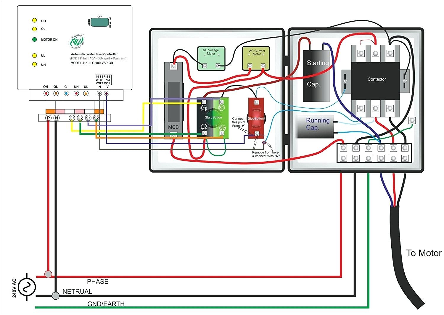
3 wire single phase submersible pump wiring diagram. 3 wire submersible well wiring diagram get free circuit diagram electrical circuit diagram capacitors. 3 hp single phase submersible pump starter 220 440 v id. 14 3 phase submersible pump wiring diagram. This will be the complete guide of controlling a three phase submersible pump motor using magnetic contactor.
 Source: tonetastic.info
4 submersible pumps two and three wire single and. 240 volt well pump wiring diagram wiring diagram is a simplified all right pictorial representation of an electrical circuit it shows the components of the circuit. Another thing which you will discover a. Three phase submersible pump wiring diagram. 3 phase to single phase wiring diagram in 2021 electrical wiring diagram diagram circuit diagram submersible pump control box wiring diagram for 3 wire single phase submersible pump submersible well pump submersible

3 wire submersible pump wiring diagram welcome to my web site this message will go over about 3 wire submersible pump wiring diagram. It consists of directions and diagrams for different types of wiring techniques as well as other items like lights windows and so forth. 3 wire submersible well wiring diagram get free circuit diagram electrical circuit diagram capacitors. Three phase submersible pump wiring diagram. A wiring diagram is a streamlined standard pictorial depiction of an electric circuit.
 Source: annawiringdiagram.com
Wiring diagram arrives with several easy to stick to wiring diagram guidelines. The first element is symbol that indicate electrical element from the circuit. Beyond these limits, the relay trips and protects the motor the auto unit in bch submersible panel primarily detects the presence or absence of all three phase. The diagram provides visual representation of a electrical structure. Gate, wiring diagrams for electrical receptacle outlets do it, wiring diagram three phase 230v bjm pumps, 3 phase submersible pump wiring diagram with dol stater, 115 volts or 220 volts to well pump terry love plumbing, wiring a water well pump controller and switch, correct wiring for 3 wire single phase motor electrical,.
 Source: electricalonline4u.com
Wiring diagram for 220 volt submersible pump water pumps submersible submersible pump. 3 phase to single phase wiring diagram in 2021 electrical wiring diagram diagram circuit diagram submersible pump control box wiring diagram for 3 wire single phase submersible pump submersible well pump submersible Aim manual page 54 single phase motors and controls motor maintenance north america water franklin electric submersible pump wiring diagram control panel pumping station png 1000x648px circuit component microcontroller three power environment electronics electrical wires cable relay pngwing china 18 warranty time soft starter 37kw for. It really is supposed to assist each of the average user in creating a proper method. Wiring diagram line we are make source the schematics, wiring diagrams and technical photos.
 Source: rajuyolo06.blogspot.com
Three phase submersible pump wiring diagram. Wiring diagram for 220 volt submersible pump water pumps submersible submersible pump. Three phase wiring diagram for house wiring diagram line wiring diagram. Aim manual page 54 single phase motors and controls motor maintenance north america water franklin electric submersible pump wiring diagram control panel pumping station png 1000x648px circuit component microcontroller three power environment electronics electrical wires cable relay pngwing china 18 warranty time soft starter 37kw for. 240 volt well pump wiring diagram wiring diagram is a simplified all right pictorial representation of an electrical circuit it shows the components of the circuit.
![[DIAGRAM] Zoeller Submersible Pump Wiring Diagram FULL [DIAGRAM] Zoeller Submersible Pump Wiring Diagram FULL](https://inspectapedia.com/water/Submersible-well-pump-wire-Tests-Goulds.jpg) Source: diagram54chef.puliziasconfinata.it
Source: diagram54chef.puliziasconfinata.it
Aim manual page 55 single phase motors and controls motor maintenance north america water franklin electric. Aim manual page 55 single phase motors and controls motor maintenance north america water franklin electric. 3 wire submersible pump wiring diagram welcome to my web site this message will go over about 3 wire submersible pump wiring diagram. 3 wire single phase submersible pump wiring diagram. Direct on line dol wiring diagram for 3 phase with 110 230vac control circuit electrical circuit diagram circuit diagram electrical wiring.
 Source: dentistmitcham.com
It has on time delay A wiring diagram is a streamlined traditional photographic representation of an electrical circuit. A wiring diagram is a streamlined standard pictorial depiction of an electric circuit. Phase controller wiring phase failure relay diagram electrical wiring electrical circuit diagram home electrical wiring. 14 3 phase submersible pump wiring diagram.

Float switch connection auto manual single phase water pump youtube electrical circuit diagram. However, the diagram is a simplified version of this structure. Wiring diagram for 220 volt submersible pump water pumps submersible submersible pump. Submersible pump control box wiring diagram for 3 wire single phase submersible pump submersible electrical circuit diagram. 3 wire float switch wiring diagram.wiring diagram includes many detailed illustrations that display the relationship of various items.

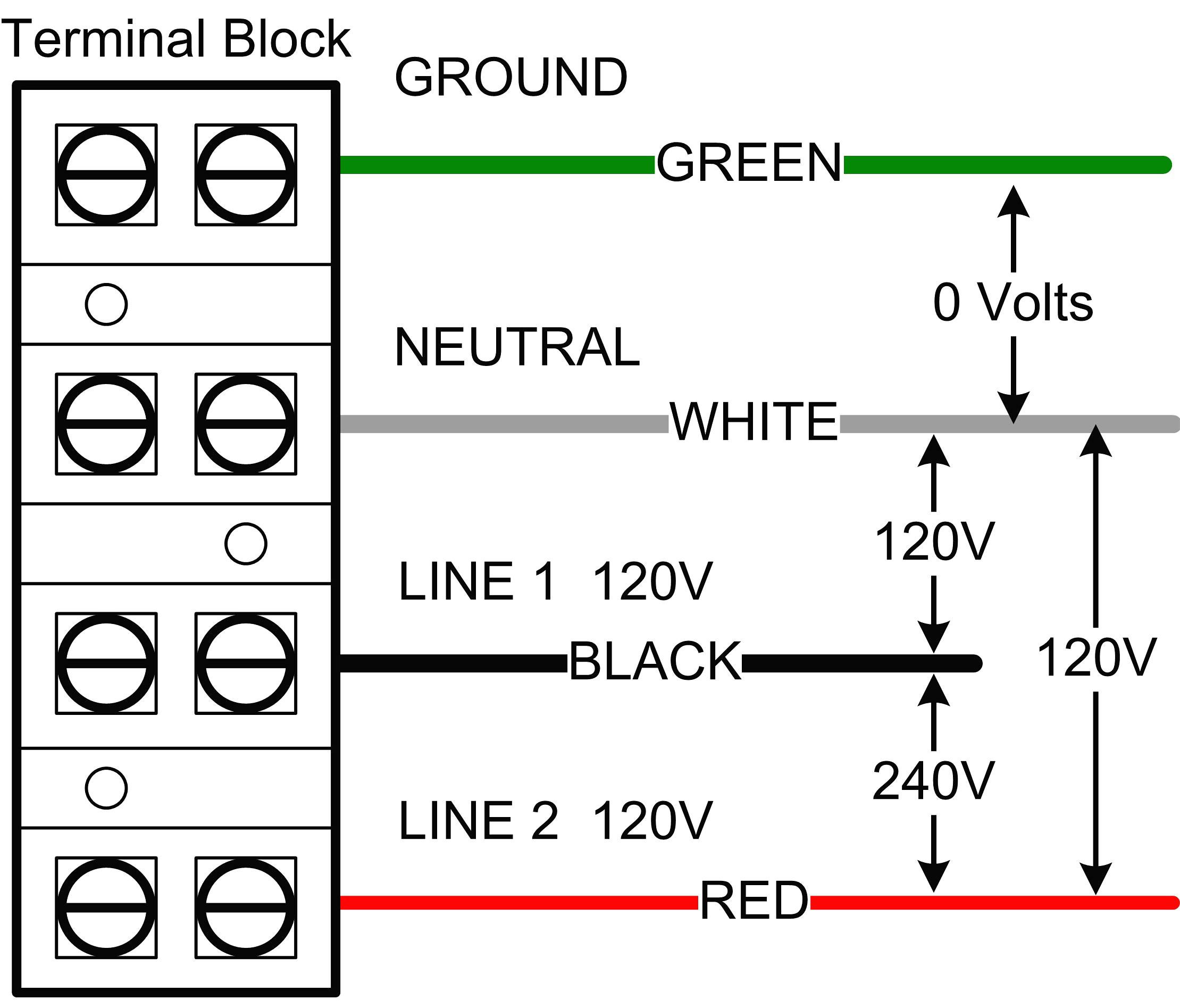
The relay allows minor imbalance in voltage conditions in the three phases within the limits motors are designed to withstand. However, the diagram is a simplified version of this structure. 3 phase submersible pump motor and electric wiring connection. The first step is to figure out the voltage of your phases. This will be the complete guide of controlling a three phase submersible pump motor using magnetic contactor.
 Source: annawiringdiagram.com
In the diagram, i showed the 3 pole mccb breaker, magnetic contactor, thermal overload protection relay, and normally open, normally close push button switches. Gate, wiring diagrams for electrical receptacle outlets do it, wiring diagram three phase 230v bjm pumps, 3 phase submersible pump wiring diagram with dol stater, 115 volts or 220 volts to well pump terry love plumbing, wiring a water well pump controller and switch, correct wiring for 3 wire single phase motor electrical,. It really is supposed to assist each of the average user in creating a proper method. Wiring diagrams 22 23 typical wiring a diagrams 3 1 2 5 36 97 3 4 31 42 1 l1 t1 t2 t3 2 l2 3 start hand/off/auto to pump motor ground level control ground pressure switch lower upper electrode to fused disconnect or circuit breaker 3ø furnas pumping panel line load line load 3 phase starter input power (as required by. The first element is symbol that indicate electrical element from the circuit.
 Source: annawiringdiagram.com
It really is supposed to assist each of the average user in creating a proper method. 3 wire single phase submersible pump wiring diagram. Ad get 3 submersible pump. R , y, b = red, yellow, blue ( 3 phase lines)c.b = general circuit breakermain = mai supplyy = starδ = deltac1, c2, c3 = contatcors (power diagram)o/l = over load relayno = normally opennc = normally closed k1 = contactor (contactor coil) k1/no = contactor holding coil (normally open)k1 , k2, k3 = contators (for control diagram ) Wiring diagrams 22 23 typical wiring a diagrams 3 1 2 5 36 97 3 4 31 42 1 l1 t1 t2 t3 2 l2 3 start hand/off/auto to pump motor ground level control ground pressure switch lower upper electrode to fused disconnect or circuit breaker 3ø furnas pumping panel line load line load 3 phase starter input power (as required by.
![[DIAGRAM] 3 Phase Submersible Pump Wiring Diagram FULL [DIAGRAM] 3 Phase Submersible Pump Wiring Diagram FULL](https://i2.wp.com/patentimages.storage.googleapis.com/US6632072B2/US06632072-20031014-D00002.png) Source: reseaudemos.niberma.fr
Source: reseaudemos.niberma.fr
240 volt well pump wiring diagram wiring diagram is a simplified all right pictorial representation of an electrical circuit it shows the components of the circuit. 3 phase submersible pump motor and electric wiring connection. A wiring diagram is a streamlined traditional photographic representation of an electrical circuit. Wiring diagram includes many detailed illustrations that display the relationship of various items. 3 wire submersible well wiring diagram get free circuit diagram electrical circuit diagram capacitors.
 Source: youtube.com
A circuit is usually composed by several components. 3 phase submersible pump control panel circuit diagram. Submersible pump microcontroller wiring diagram three phase electric power png 1000x648px circuit breaker submersible pump panel 3 phase control manufacturer from ahmedabad sim a three phase simplex pump control panel see water inc Wiring diagram for 220 volt submersible pump water pumps submersible submersible pump. Wiring diagram includes many detailed illustrations that display the relationship of various items.
This site is an open community for users to do sharing their favorite wallpapers on the internet, all images or pictures in this website are for personal wallpaper use only, it is stricly prohibited to use this wallpaper for commercial purposes, if you are the author and find this image is shared without your permission, please kindly raise a DMCA report to Us.
If you find this site value, please support us by sharing this posts to your own social media accounts like Facebook, Instagram and so on or you can also save this blog page with the title three phase submersible pump wiring diagram by using Ctrl + D for devices a laptop with a Windows operating system or Command + D for laptops with an Apple operating system. If you use a smartphone, you can also use the drawer menu of the browser you are using. Whether it’s a Windows, Mac, iOS or Android operating system, you will still be able to bookmark this website.
Category
Related By Category
- Predator 670 engine wiring diagram Idea
- Frsky x8r wiring diagram information
- Pioneer ts wx130da wiring diagram Idea
- Johnson 50 hp wiring diagram Idea
- Kohler voltage regulator wiring diagram Idea
- Johnson 50 hp outboard wiring diagram information
- Kti hydraulic remote wiring diagram Idea
- Pyle plpw12d wiring diagram information
- Tx9600ts wiring diagram information
- Lifan 50cc wiring diagram information