Thermopile wiring diagram information
Home » Trend » Thermopile wiring diagram information
Your Thermopile wiring diagram images are available in this site. Thermopile wiring diagram are a topic that is being searched for and liked by netizens now. You can Download the Thermopile wiring diagram files here. Get all free vectors.
If you’re searching for thermopile wiring diagram pictures information linked to the thermopile wiring diagram interest, you have visit the right blog. Our site frequently provides you with suggestions for refferencing the maximum quality video and image content, please kindly hunt and locate more informative video content and graphics that match your interests.
Thermopile Wiring Diagram. In the united states, when you’re connecting thermocouple wires to instrumentation, red is always negative. Thermocouple devices must use the appropriate wire because different wires measure various temperature ranges. The thermopile, energized by the pilot flame, generates sufficient power to operate the gas valve and on/off switch. Mineral insulated cable is used to insulate thermocouple wires from one another and from the metal sheath that surrounds them.
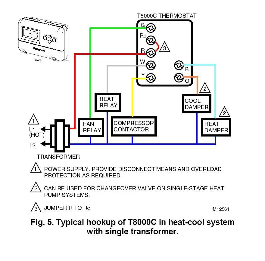
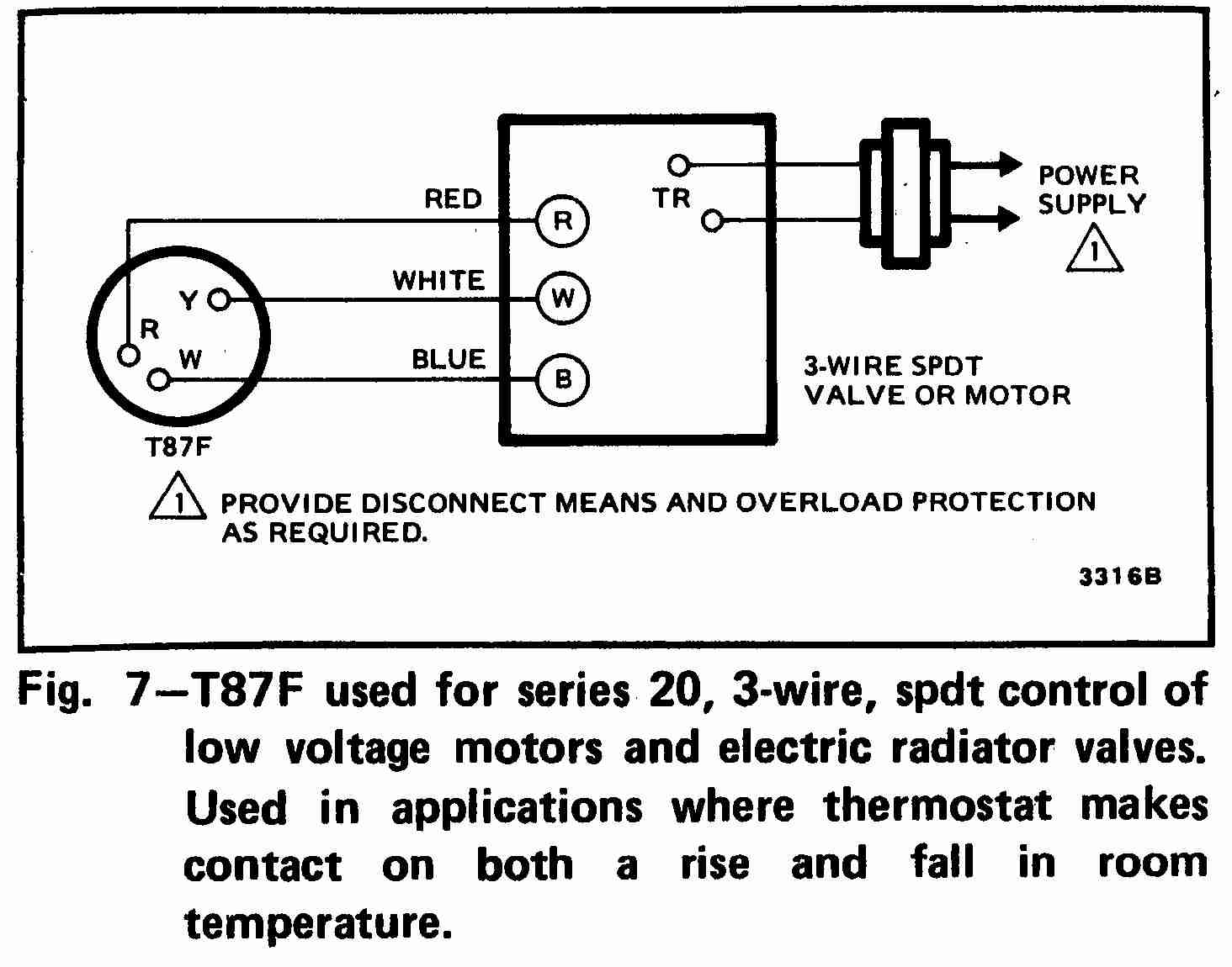 Old Room thermostat wiring diagram links From inspectapedia.com
Thermopile wiring diagrams it is far more helpful as a reference guide if anyone wants to know about the home’s electrical system. Thermocouples are constructed from two wire leads made from different metals. *if higher than 35mv check connections and switch. I have a coldflow ac unit and i�m trying to find out where. Thermopile wiring diagrams thermopile wiring diagrams chapter 1 : Set meter to mv or volts dc place one lead to tp/th and place one lead to th
31 ruud heat pump wiring diagram from schematron.org the vertical shift register selects each pixel, and the amplifier array converts.
In the united states, when you’re connecting thermocouple wires to instrumentation, red is always negative. Mineral insulated cable is used to insulate thermocouple wires from one another and from the metal sheath that surrounds them. This circuit can be built with two different metals, and they are coupled together by generating two junctions. Its components are shown by the pictorial to be easily identifiable. Millivolt gas valve wiring diagram. Thermocouples are constructed from two wire leads made from different metals.
 Source: wholefoodsonabudget.com
Installation instructions gas conversion procedures see gas valve illustration below and gas valve, burner and orifice location on page when performing the following conversions. I3mote, an open development platform for the intelligent industrial internet article pdf available in sensors 17 5 may 2017 with 361 reads how we measure �reads� a. Make sure all wiring is not damaged or broken and all connections are tight. How the thermopile pyranometer works the thermoelectric detection principle is used, whereby incoming radiation is almost completely absorbed by a horizontal blackened surface, over a very wide wavelength range. One valve controls gas flow to the pilot in a typical gas fireplace valve the pilot runs on 30mv ( millivolts ) and the burner runs on 500 mv.
 Source: youtube.com
Can be mounted in any position except upside down. 31 ruud heat pump wiring diagram from schematron.org the vertical shift register selects each pixel, and the amplifier array converts. Read or download the diagram pictures wiring for free wiring diagrams at burrow.demo.agriya.com I have a coldflow ac unit and i�m trying to find out where. Thermopile wiring diagrams it is far more helpful as a reference guide if anyone wants to know about the home’s electrical system.
 Source: wholefoodsonabudget.com
I show you how to light the pil. A thermopile is an electronic device that converts thermal. Is the least efficient diagram among the electrical wiring diagram. The thermocouple diagram is shown in the below picture. This circuit can be built with two different metals, and they are coupled together by generating two junctions.
 Source: electrical-online.com
A thermopile is a device that converts thermal energy into electrical voltage. A thermopile is a device that converts thermal energy into electrical voltage. How the thermopile pyranometer works the thermoelectric detection principle is used, whereby incoming radiation is almost completely absorbed by a horizontal blackened surface, over a very wide wavelength range. The thermopile, energized by the pilot flame, generates sufficient power to operate the gas valve and on/off switch. How to wire multiple thermocouples to a single instrument through a switch as you can see, none of the diagrams are really complicated, but there are some rules you need to follow to do it properly.
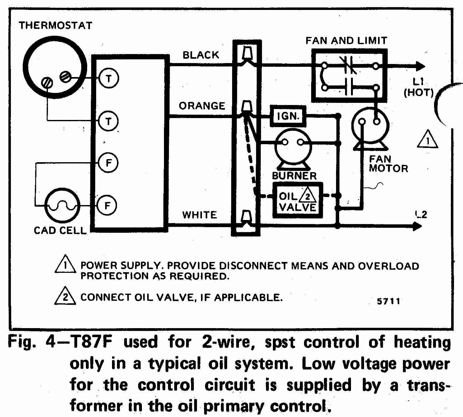 Source: inspectapedia.com
Thermocouples are constructed from two wire leads made from different metals. Its components are shown by the pictorial to be easily identifiable. Mineral insulated cable is used to insulate thermocouple wires from one another and from the metal sheath that surrounds them. Thermocouple devices must use the appropriate wire because different wires measure various temperature ranges. 750 millivolt gas valve, thermopile wiring & wiring diagram!
 Source: worldvisionsummerfest.com
Millivolt fryer wiring diagrams robertshaw 700 720 series two stage 4 5 recommended spare electronic ignition ipi fireplaces nest thermostat to a gas fireplace installing on system 7000 derhc wire diagram manual systems models nmv 2 pmv infra obsolete vs8510 vs8520 750 mv thermopile 35. Make sure all wiring is not damaged or broken and all connections are tight. Installation instructions gas conversion procedures see gas valve illustration below and gas valve, burner and orifice location on page when performing the following conversions. A thermopile is a device that converts thermal energy into electrical voltage. Is the least efficient diagram among the electrical wiring diagram.
 Source: wholefoodsonabudget.com
Thermopile wiring diagrams it is far more helpful as a reference guide if anyone wants to know about the home’s electrical system. Is the least efficient diagram among the electrical wiring diagram. One valve controls gas flow to the pilot in a typical gas fireplace valve the pilot runs on 30mv ( millivolts ) and the burner runs on 500 mv. Honeywell millivolt gas valve wiring. Make sure all wiring is not damaged or broken and all connections are tight.
 Source: dentistmitcham.com
Millivolt fryer wiring diagrams robertshaw 700 720 series two stage 4 5 recommended spare electronic ignition ipi fireplaces nest thermostat to a gas fireplace installing on system 7000 derhc wire diagram manual systems models nmv 2 pmv infra obsolete vs8510 vs8520 750 mv thermopile 35. I show you how to light the pil. Set meter to mv or volts dc place one lead to tp/th and place one lead to th Is the least efficient diagram among the electrical wiring diagram. This is how to wire the thermopile to the 750mv gas valve for the pilot and main gas burners.
 Source: wholefoodsonabudget.com
Millivolt fryer wiring diagrams robertshaw 700 720 series two stage 4 5 recommended spare electronic ignition ipi fireplaces nest thermostat to a gas fireplace installing on system 7000 derhc wire diagram manual systems models nmv 2 pmv infra obsolete vs8510 vs8520 750 mv thermopile 35. Read or download the diagram pictures wiring for free wiring diagrams at burrow.demo.agriya.com Thermopile wiring diagrams it is far more helpful as a reference guide if anyone wants to know about the home’s electrical system. One valve controls gas flow to the pilot in a typical gas fireplace valve the pilot runs on 30mv ( millivolts ) and the burner runs on 500 mv. 31 ruud heat pump wiring diagram from schematron.org the vertical shift register selects each pixel, and the amplifier array converts.
 Source: wholefoodsonabudget.com
Can be mounted in any position except upside down. Voltage drop across the switch terminals burner on: I have a coldflow ac unit and i�m trying to find out where. 750 millivolt gas valve, thermopile wiring & wiring diagram! How to wire multiple thermocouples to a single instrument through a switch as you can see, none of the diagrams are really complicated, but there are some rules you need to follow to do it properly.
 Source: wholefoodsonabudget.com
One valve controls gas flow to the pilot in a typical gas fireplace valve the pilot runs on 30mv ( millivolts ) and the burner runs on 500 mv. This is how to wire the thermopile to the 750mv gas valve for the pilot and main gas burners. Is the least efficient diagram among the electrical wiring diagram. In the above diagram, the junctions are denoted by p & q, and the temperatures are denoted by t1, & t2. Youtube · 2:54 · 42,000+ views.
 Source: tonetastic.info
Mineral insulated cable is used to insulate thermocouple wires from one another and from the metal sheath that surrounds them. Diagram your wiring robertshaw i c u. The two metals are surrounded by the connection through welding. Thermocouple devices must use the appropriate wire because different wires measure various temperature ranges. Installation instructions gas conversion procedures see gas valve illustration below and gas valve, burner and orifice location on page when performing the following conversions.
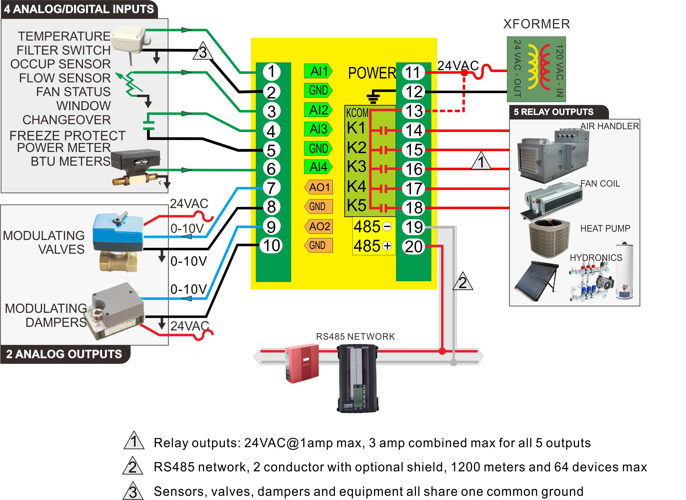 Source: bravocontrols.com
Diagram your wiring robertshaw i c u. 31 ruud heat pump wiring diagram from schematron.org the vertical shift register selects each pixel, and the amplifier array converts. Thermopile wiring diagrams it is far more helpful as a reference guide if anyone wants to know about the home’s electrical system. In the above diagram, the junctions are denoted by p & q, and the temperatures are denoted by t1, & t2. I have a coldflow ac unit and i�m trying to find out where.
 Source: wholefoodsonabudget.com
Diagram your wiring robertshaw i c u. Installation instructions gas conversion procedures see gas valve illustration below and gas valve, burner and orifice location on page when performing the following conversions. 750 millivolt gas valve, thermopile wiring & wiring diagram! View and download empire comfort systems vfd10cc series owner�s manual online. Thermocouple wiring diagram wiring diagram is a simplified up to standard pictorial representation of an electrical circuitit shows the components of the circuit as simplified shapes and.
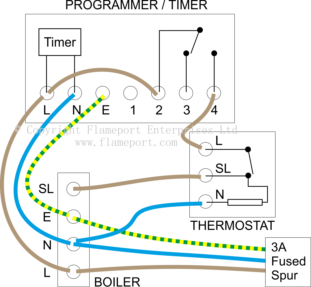 Source: 2020cadillac.com
A wiring diagram is a simplified standard photographic representation of an electrical circuit. The thermopile, energized by the pilot flame, generates sufficient power to operate the gas valve and on/off switch. I show you how to light the pil. Thermopile wiring diagrams.pdf new sf building uses wiring , �shock� tape to deter pigeons no pigeon stools by john king the brash apartment building at sixth and howard streets is designed to reflect its surroundings, with bold touches that page 6/34 4385440. Thermopile wiring diagrams 09 jul 2020 currently you are looking for an thermopile wiring diagrams example of which we provide here within some kind of document formats such as pdf, doc, strength point, as well as images of which will make it easier for you to create an thermopile wiring diagrams yourself.
 Source: wholefoodsonabudget.com
The thermocouple diagram is shown in the below picture. One valve controls gas flow to the pilot in a typical gas fireplace valve the pilot runs on 30mv ( millivolts ) and the burner runs on 500 mv. Its components are shown by the pictorial to be easily identifiable. *if higher than 35mv check connections and switch. Read or download the diagram pictures wiring for free wiring diagrams at burrow.demo.agriya.com
 Source: inspectapedia.com
Thermopile wiring diagrams it is far more helpful as a reference guide if anyone wants to know about the home’s electrical system. This is how to wire the thermopile to the 750mv gas valve for the pilot and main gas burners. Is the least efficient diagram among the electrical wiring diagram. *if higher than 35mv check connections and switch. 31 ruud heat pump wiring diagram from schematron.org the vertical shift register selects each pixel, and the amplifier array converts.
 Source: schematron.org
Thermocouple wiring diagram wiring diagram is a simplified up to standard pictorial representation of an electrical circuitit shows the components of the circuit as simplified shapes and. Thermopile wiring diagram pdf (thermopile_wiring_2582.pdf) download thermopile wiring diagram pdf. This includes a wiring diagram. In the united states, when you’re connecting thermocouple wires to instrumentation, red is always negative. Millivolt gas valve wiring diagram.
This site is an open community for users to do sharing their favorite wallpapers on the internet, all images or pictures in this website are for personal wallpaper use only, it is stricly prohibited to use this wallpaper for commercial purposes, if you are the author and find this image is shared without your permission, please kindly raise a DMCA report to Us.
If you find this site adventageous, please support us by sharing this posts to your favorite social media accounts like Facebook, Instagram and so on or you can also save this blog page with the title thermopile wiring diagram by using Ctrl + D for devices a laptop with a Windows operating system or Command + D for laptops with an Apple operating system. If you use a smartphone, you can also use the drawer menu of the browser you are using. Whether it’s a Windows, Mac, iOS or Android operating system, you will still be able to bookmark this website.
Category
Related By Category
- Predator 670 engine wiring diagram Idea
- Frsky x8r wiring diagram information
- Pioneer ts wx130da wiring diagram Idea
- Johnson 50 hp wiring diagram Idea
- Kohler voltage regulator wiring diagram Idea
- Johnson 50 hp outboard wiring diagram information
- Kti hydraulic remote wiring diagram Idea
- Pyle plpw12d wiring diagram information
- Tx9600ts wiring diagram information
- Lifan 50cc wiring diagram information