Thermal overload switch wiring diagram information
Home » Trending » Thermal overload switch wiring diagram information
Your Thermal overload switch wiring diagram images are ready. Thermal overload switch wiring diagram are a topic that is being searched for and liked by netizens today. You can Get the Thermal overload switch wiring diagram files here. Get all royalty-free images.
If you’re looking for thermal overload switch wiring diagram pictures information linked to the thermal overload switch wiring diagram keyword, you have visit the right blog. Our website frequently provides you with suggestions for seeing the highest quality video and image content, please kindly surf and find more enlightening video content and images that match your interests.
Thermal Overload Switch Wiring Diagram. Insert the metallic rod terminals of the overload relay to the bottom side of the contactor as shown in the above figure, then tighten the screws. It shows the components of the circuit as simplified shapes, and the talent and signal links together with the devices. Bearing in mind aggravating to remove, replace or repair the wiring in an automobile, having an accurate and detailed thermal overload switch. The three klixon terminals are used to handle motor protection properly in v and v operations.
 Thermal Overload Relay Wiring Diagram Gallery From wholefoodsonabudget.com
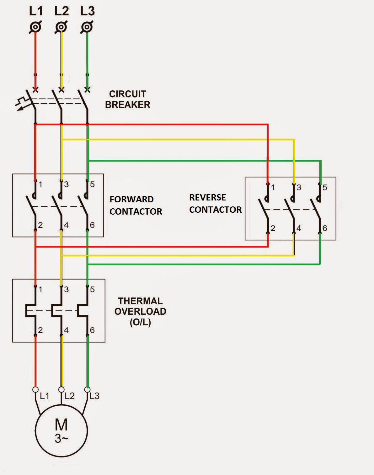
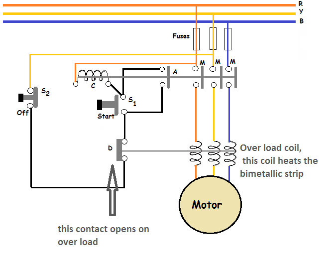
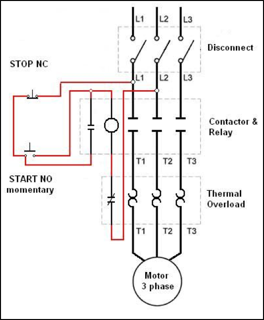
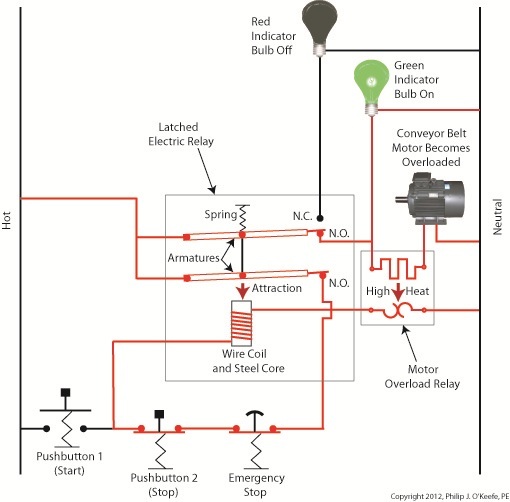
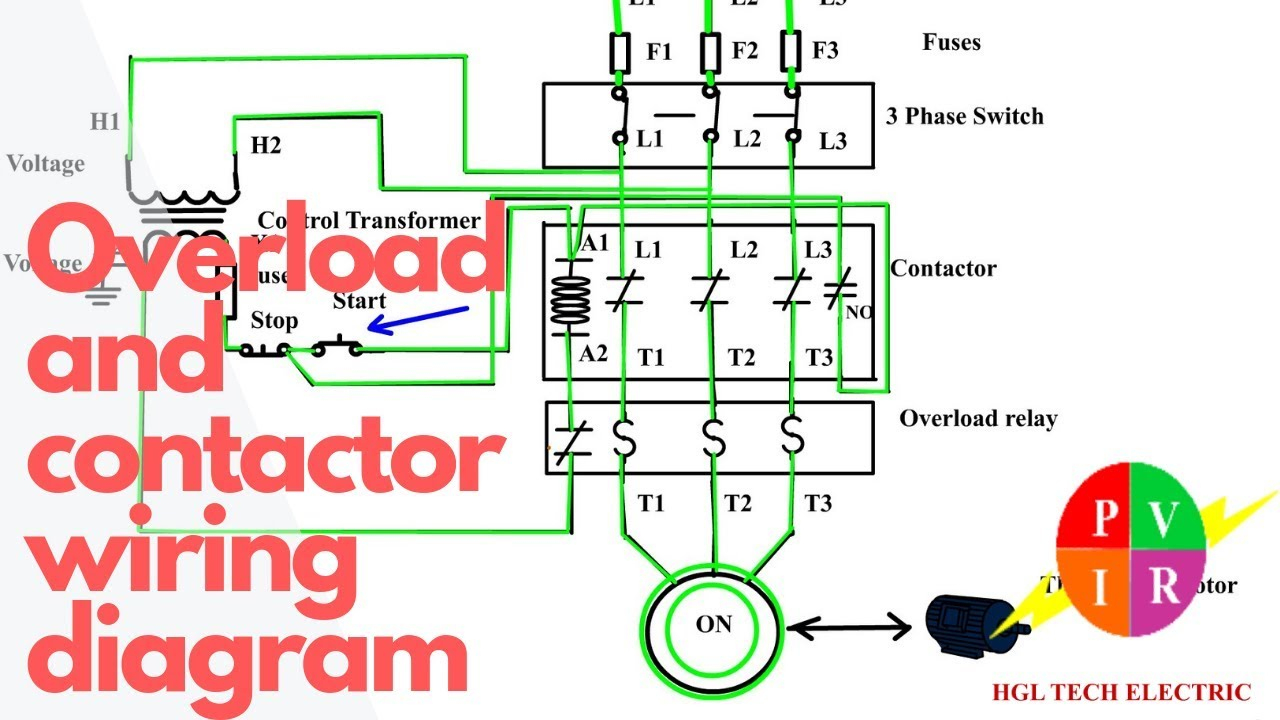
In this wiring diagram contactor, i shown thermal overload relay however soon i will make a diagram about electronic relay. Diagram plugging of induction motor automatic brake failure indicator ac drives regenerative braking circuits mte thermal overload relay contactor wiring diagram with timer brake failure indicator 5.5kw induction motor wiring diagram dol motor starter. 240 volt well pump wiring diagram wiring diagram is a simplified all right pictorial representation of an electrical circuit it shows the components of the circuit as simplified shapes and the faculty and signal contacts amongst the devices. The thermal overloads in the panel must be set to the f.l.a. The black wire is a mains lead, and has a thermal overload switch on it (the weird symbol on the third wire down.) the red, blue, yellow and white wires connect to split coils, and are to be connected to each other and the other mains lead as shown on the diagrams for 120 or. How to wire a contactor direct on line motor starter diagram in and overload wiring for contactor and overload wiring electrical circuit diagram motor diagram.
1995 freightliner fl70 wiring diagram.
A klixon is an overload protector used mostly in fractional horsepower if i have it, i will get the schematic for you. The thermal switch has 3 wires to it. A klixon is an overload protector used mostly in fractional horsepower if i have it, i will get the schematic for you. If not, the arrangement won’t function as it ought to be. The three klixon terminals are used to handle motor protection properly in v and v operations. The reset adjustment method of thermal overload relay can be.
 Source: electrialstandards.blogspot.com
Thermal switches can be loaded as followed: U max = 250 v ac i n = 1.5 a. Heater feeder is protected only by conventional switch fuse unit. The second type of internal protection is the thermistors or positive temperature coefficient sensors (ptc). It shows the components of the circuit as simplified shapes, and the talent and signal links together with the devices.
 Source: okplazas.com
First of all wire the cb circuit breaker but do not switch on. 1995 freightliner fl70 wiring diagram. The thermal switch has 3 wires to it. Overload relay connection diagram maintained switch wiring for magnetic motor direct online starter a single phase through 3 thermal electronics arduino rasbery pi ex sizing the dol parts following chegg on line overload relay connection diagram types and applications contactor overload maintained switch wiring for magnetic motor ee cambodia how to wire. These lines far exceed the 120 volts ac standard in most homes.
 Source: tonetastic.info
The overload relay working/function is discussed below. Single speed hoist, single speed trolley,. Insert the metallic rod terminals of the overload relay to the bottom side of the contactor as shown in the above figure, then tighten the screws. The thermal switch has 3 wires to it. Desember 06, 2021 add comment edit.
 Source: denor.com
The overload relay working/function is discussed below. The wiring diagram of an overload relay is shown below, and the connections of an overload relay symbol may seem like two opposite question marks otherwise like the ‘s’ symbol. If not, the arrangement won’t function as it ought to be. The above wiring diagram shows a typical hookup for a volt , 3 phase pump,. Jan 29, · 2) the klixon in the gwi circuit (from greg�s wiring diagram).
 Source: worldvisionsummerfest.com
U max = 250 v ac i n = 1.5 a. The overload relay olr has a total of six main power terminals. Following maddening to remove, replace or fix the wiring in an automobile, having an accurate and detailed thermal overload wiring diagram. Single speed hoist, single speed trolley,. Single action control switches can only be connected through a control panel.
 Source: yourelectricalguide.com
Electric motor overload breaker reset switch electric motor parts wiring. A wiring diagram is a simplified traditional pictorial representation of an electrical circuit. Bearing in mind aggravating to remove, replace or repair the wiring in an automobile, having an accurate and detailed thermal overload switch. Thermal overload switch wiring diagram by. The reset adjustment method of thermal overload relay can be.
 Source: wholefoodsonabudget.com
The pain in fact is that all car is different. There is also a knob for adjusting the current. The wiring starter circuit breaker and thermal overloads are. Siemens 3 2a 3 pole thermal overload relay 3ru21 16 1db0 switch gears electricals siemens electrical wiring electrical installation. Jan 29, · 2) the klixon in the gwi circuit (from greg�s wiring diagram).
 Source: earthbondhon.com
Thermal switches can be loaded as followed: 1995 freightliner fl70 wiring diagram. 3 phase contactor with overload wiring diagram. Three wire pumps need an extra control panel above ground. The thermal switch has 3 wires to it.
 Source: wiring121.blogspot.com
3 phase motor contactor wiring diagram a novice s guide to circuit diagrams. The thermal switch has 3 wires to it. Insert the metallic rod terminals of the overload relay to the bottom side of the contactor as shown in the above figure, then tighten the screws. Single phase units have an internal thermal overload. 1 trick that we 2 to printing a similar wiring plan off twice.
 Source: chegg.com
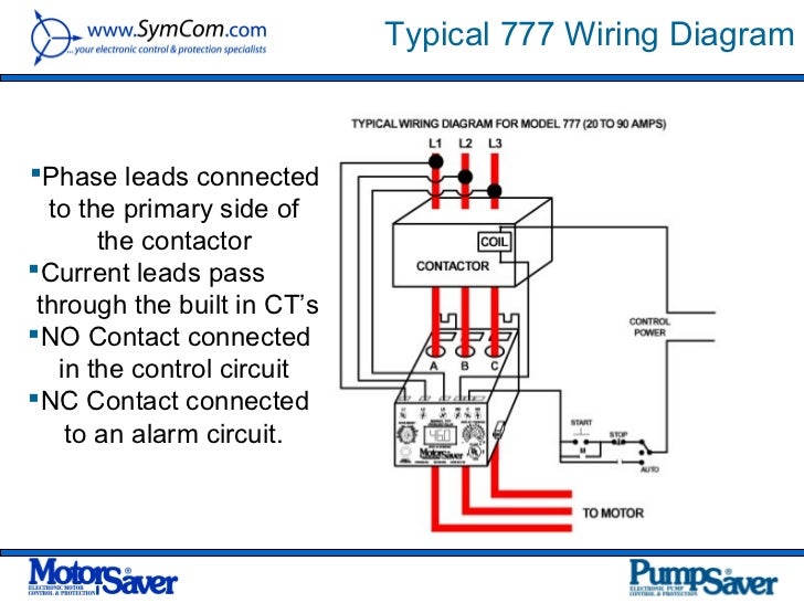
The above wiring diagram shows a typical hookup for a volt , 3 phase pump,. The overload relay working/function is discussed below. I want to know how to bypass the thermal overload switch so i can see if the motor runs. Bearing in mind aggravating to remove, replace or repair the wiring in an automobile, having an accurate and detailed thermal overload switch. Insert the metallic rod terminals of the overload relay to the bottom side of the contactor as shown in the above figure, then tighten the screws.
 Source: worldvisionsummerfest.com
The second type of internal protection is the thermistors or positive temperature coefficient sensors (ptc). In this wiring diagram contactor, i shown thermal overload relay however soon i will make a diagram about electronic relay. Wiring diagram contactor and overload wiring diagram technic contactor relay wiring wiring diagram datasource. Single speed hoist, single speed trolley,. The reset adjustment method of thermal overload relay can be.
 Source: wholefoodsonabudget.com
I want to know how to bypass the thermal overload switch so i can see if the motor runs. Wiring diagrams do not show the operating mechanism since it is not electrically controlled. The above wiring diagram shows a typical hookup for a volt , 3 phase pump,. The thermal overloads in the panel must be set to the f.l.a. 240 volt well pump wiring diagram wiring diagram is a simplified all right pictorial representation of an electrical circuit it shows the components of the circuit as simplified shapes and the faculty and signal contacts amongst the devices.
 Source: tonetastic.info
Paddle limit switch geared limit switch fuses thermal overload relay overload switch power paddle thermal switch wiring diagram; In this wiring diagram contactor, i shown thermal overload relay however soon i will make a diagram about electronic relay. The overload relay operates the contactor to get turned when an overload fault occurs. These lines far exceed the 120 volts ac standard in most homes. 3 phase motor contactor wiring diagram a novice s guide to circuit diagrams.
 Source: engineeringexpert.net
Wiring diagrams do not show the operating mechanism since it is not electrically controlled. How to wire a contactor direct on line motor starter diagram in and overload wiring for contactor and overload wiring electrical circuit diagram motor diagram. The pain in fact is that all car is different. Wiring diagram contactor and overload wiring diagram technic contactor relay wiring wiring diagram datasource. 3 phase contactor with overload wiring diagram.
 Source: worldvisionsummerfest.com
The motor is 110/220 and i think it is wired for 220 now. 3 phase contactor with start stop wiring diagram i 2020 for 3 phase motor controlling diagram and procedure follow the below tips. 3 phase contactor with overload wiring diagram. Siemens 3 2a 3 pole thermal overload relay 3ru21 16 1db0 switch gears electricals siemens electrical wiring electrical installation. In this wiring diagram contactor, i shown thermal overload relay however soon i will make a diagram about electronic relay.
 Source: 2020cadillac.com
Paddle limit switch geared limit switch fuses thermal overload relay overload switch power paddle thermal switch wiring diagram; Bmw thermo switch wiring diagram from cdn.shopify.com print the wiring diagram off plus use highlighters to trace the signal. A wiring diagram is a simplified traditional pictorial representation of an electrical circuit. The black wire is a mains lead, and has a thermal overload switch on it (the weird symbol on the third wire down.) the red, blue, yellow and white wires connect to split coils, and are to be connected to each other and the other mains lead as shown on the diagrams for 120 or. Thermal overload relay reset adjustment instructions generally, the red button on the front of the device is the stop button, and the blue button is the reset button.
 Source: schematron.org
The wiring starter circuit breaker and thermal overloads are. The thermal switch has 3 wires to it. Single speed hoist, single speed trolley: The overload relay working/function is discussed below. Heater feeder is protected only by conventional switch fuse unit.
 Source: electrialstandards.blogspot.com
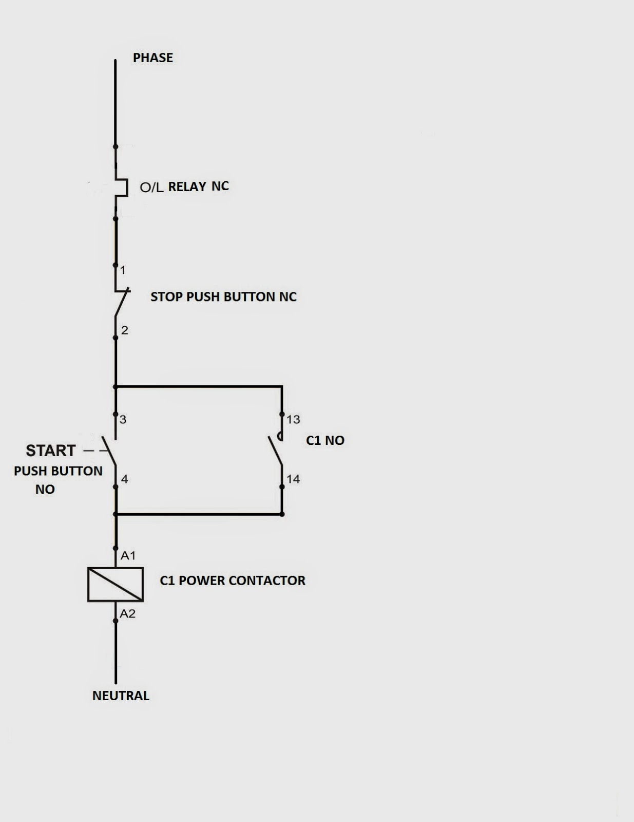
Following maddening to remove, replace or fix the wiring in an automobile, having an accurate and detailed thermal overload wiring diagram. Thermal overload switch wiring diagram by. Three wire pumps need an extra control panel above ground. 3 phase motor contactor wiring diagram a novice s guide to circuit diagrams. Jan 29, · 2) the klixon in the gwi circuit (from greg�s wiring diagram).
This site is an open community for users to submit their favorite wallpapers on the internet, all images or pictures in this website are for personal wallpaper use only, it is stricly prohibited to use this wallpaper for commercial purposes, if you are the author and find this image is shared without your permission, please kindly raise a DMCA report to Us.
If you find this site good, please support us by sharing this posts to your preference social media accounts like Facebook, Instagram and so on or you can also save this blog page with the title thermal overload switch wiring diagram by using Ctrl + D for devices a laptop with a Windows operating system or Command + D for laptops with an Apple operating system. If you use a smartphone, you can also use the drawer menu of the browser you are using. Whether it’s a Windows, Mac, iOS or Android operating system, you will still be able to bookmark this website.
Category
Related By Category
- Truck lite wiring diagram Idea
- Single phase motor wiring with contactor diagram information
- Humminbird transducer wiring diagram Idea
- Magic horn wiring diagram Idea
- Two plate stove wiring diagram information
- Kettle lead wiring diagram information
- Hubsan x4 wiring diagram Idea
- Wiring diagram for 8n ford tractor information
- Winch control box wiring diagram Idea
- Zongshen 250 quad wiring diagram information