Thermal overload relay wiring diagram Idea
Home » Trending » Thermal overload relay wiring diagram Idea
Your Thermal overload relay wiring diagram images are available in this site. Thermal overload relay wiring diagram are a topic that is being searched for and liked by netizens now. You can Get the Thermal overload relay wiring diagram files here. Get all free vectors.
If you’re searching for thermal overload relay wiring diagram pictures information linked to the thermal overload relay wiring diagram keyword, you have pay a visit to the right site. Our site always provides you with suggestions for seeking the maximum quality video and image content, please kindly hunt and find more enlightening video articles and images that fit your interests.
Thermal Overload Relay Wiring Diagram. Overload relay connection diagram thermal wiring how does a work working contactorotor starters part 2 types chegg com sizing the dol motor starter parts direct online overload relay connection diagram types and applications thermal overload relay wiring diagram and reset adjustment instructions how does a thermal overload relay work. E300 overload relay wiring diagram wiring view and schematics diagram from www.wiringview.co. Setting range type pack weight d.o.l. These lines far exceed the 120 volts ac standard in most homes.
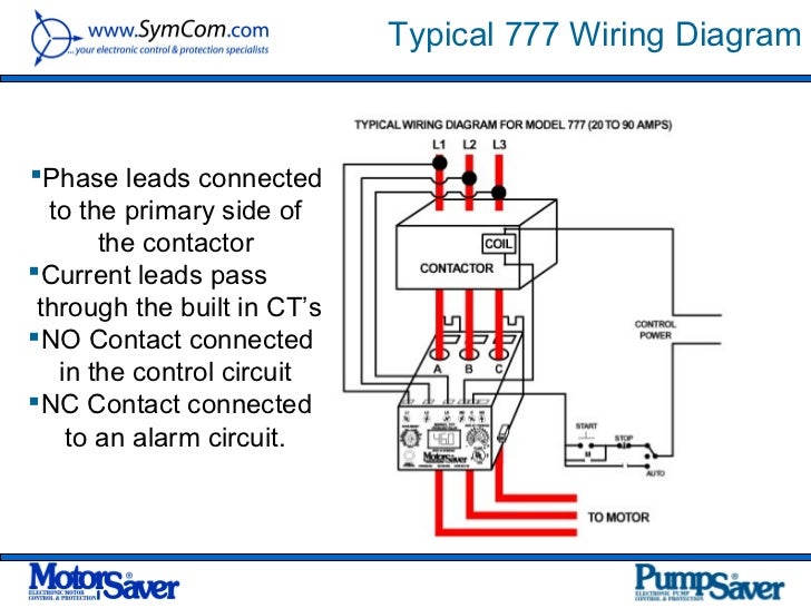
 46 Thermal Overload Relay Diagram Wiring Diagram Source From apiccolisogni.blogspot.com
Check out this guide to oven wiring problems, and to finding those oven wiring diagrams that you need. Wiring diagram contactor and overload wiring diagram technic contactor relay wiring wiring diagram datasource. Gallery thermal overload relay wiring diagram sample. Following maddening to remove, replace or fix the wiring in an automobile, having an accurate and detailed thermal overload wiring diagram. Gfci plug wiring diagram | mastercraft prostar wiring diagram | wiring diagram panel listrik | full house wiring diagram | logic gate diagram. These lines far exceed the 120 volts ac standard in most homes.
A relay can be used to power a new circuit with very little added cur.
Overload reset mode setting and phase imbalance activation; There is also a knob for adjusting the current. Handle lots of relays with only 2 wires: Siemens 3 2a 3 pole thermal overload relay 3ru21 16 1db0 switch gears electricals siemens electrical wiring electrical installation. Sst 002 98 sb 7386 sb 7361 ptm 91 6566 sst 098 98. There are two popular types o/l relay which is thermal overload relay and electronic overload relay.
 Source: worldvisionsummerfest.com
Setting range type pack weight d.o.l. Contactor and thermal overload relay wiring diagram. Handle lots of relays with only 2 wires: Trip class setting and ground fault activation; Gallery thermal overload relay wiring diagram sample.
 Source: wiringdiagramharnessideas.blogspot.com
Motor on and alarm leds ; Wiring diagram contactor and overload wiring diagram technic contactor relay wiring wiring diagram datasource. Overload relay connection diagram thermal wiring how does a work working contactorotor starters part 2 types chegg com sizing the dol motor starter parts direct online overload relay connection diagram types and applications thermal overload relay wiring diagram and reset adjustment instructions how does a thermal overload relay work. Contactor and thermal overload relay wiring diagram. E300 overload relay wiring diagram wiring view and schematics diagram from www.wiringview.co.
 Source: apiccolisogni.blogspot.com
Thermal overload relay reset adjustment instructions generally, the red button on the front of the device is the stop button, and the blue button is the reset button. A wiring diagram is a simplified traditional pictorial representation of an electrical circuit. Sst 002 98 sb 7386 sb 7361 ptm 91 6566 sst 098 98. Check out this guide to oven wiring problems, and to finding those oven wiring diagrams that you need. Diagram maker altahaddi net, amplifier thermal protection circuit wiring diagrams, thermal overload relay t16 abb group, fuses and electrical protection symbols, single phase motor contactor wiring diagram in urdu amp hindi, wiring diagrams dms hvacpartners com, thermal overload relays 3 pole
 Source: schematron.org
Product selection accessories din rail and panel mounting adapter these adapters are required when A wiring diagram is a simplified traditional pictorial representation of an electrical circuit. E300 overload relay wiring diagram wiring view and schematics diagram from www.wiringview.co. † e3 plus overload relay when features and/or functions apply specifically to it. Easy and simple wiring diagram to make you learn easily watch the vid.
 Source: wholefoodsonabudget.com
Contactor and thermal overload relay wiring diagram , related gallery: This directs the current through from l2 and directs it through the 3 rd phase on the contactor and overload l3 t3. Sst 002 98 sb 7386 sb 7361 ptm 91 6566 sst 098 98. This creates a basic memory function the relay � remembers�. Then wire the overload relay with mc.
 Source: tonetastic.info
Gallery thermal overload relay wiring diagram sample. If not, the arrangement won’t function as it ought to be. Siemens 3 2a 3 pole thermal overload relay 3ru21 16 1db0 switch gears electricals siemens electrical wiring electrical installation. This directs the current through from l2 and directs it through the 3 rd phase on the contactor and overload l3 t3. A relay can be used to power a new circuit with very little added cur.
 Source: wholefoodsonabudget.com
Thermal overload is widely used for. There are two popular types o/l relay which is thermal overload relay and electronic overload relay. Siemens 3 2a 3 pole thermal overload relay 3ru21 16 1db0 switch gears electricals siemens electrical wiring electrical installation. Gfci plug wiring diagram | mastercraft prostar wiring diagram | wiring diagram panel listrik | full house wiring diagram | logic gate diagram. Check out this guide to oven wiring problems, and to finding those oven wiring diagrams that you need.
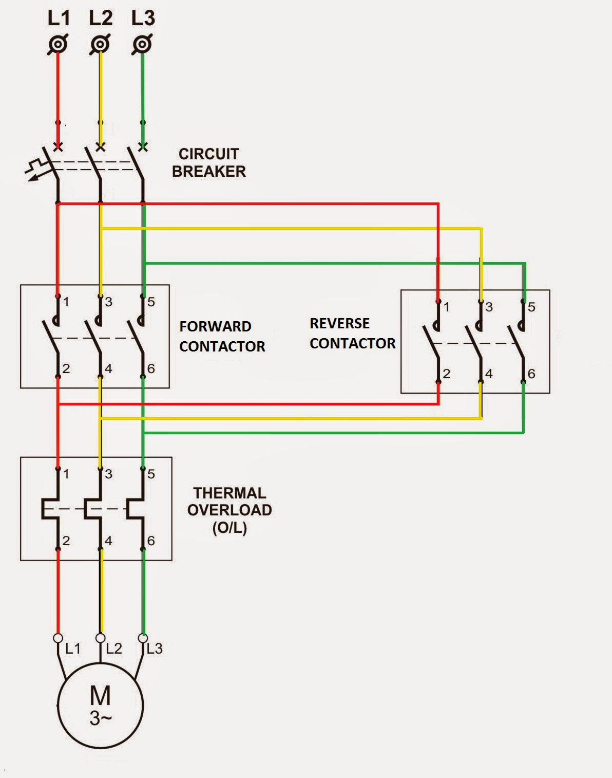 Source: electrialstandards.blogspot.com
Handle lots of relays with only 2 wires: The best unconventional is always to use a verified and accurate thermal overload switch wiring diagram that’s provided from a trusted source. Siemens 3 2a 3 pole thermal overload relay 3ru21 16 1db0 switch gears electricals siemens electrical wiring electrical installation. A wiring diagram is a simplified traditional pictorial representation of an electrical circuit. Subject to change without notice.
 Source: tonetastic.info
Dol starter control and power wiring by using a fuse, contactor, overload relay, motor. Thermal overload relays electronic overload relays. Wiring diagram since wiring connections and. You ll be able to often rely on wiring diagram as an crucial reference that may assist you to save money and time. Product selection accessories din rail and panel mounting adapter these adapters are required when
 Source: wholefoodsonabudget.com
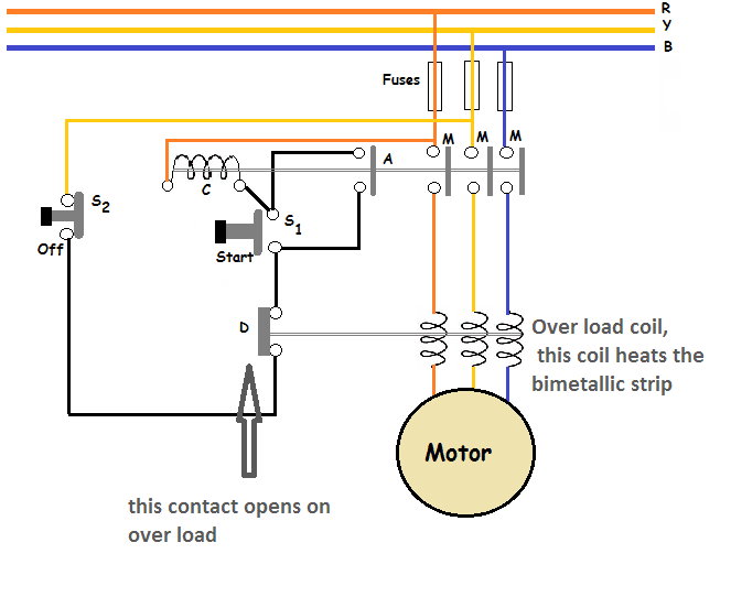
Subject to change without notice. Product selection accessories din rail and panel mounting adapter these adapters are required when Overload reset mode setting and phase imbalance activation; Overload relay connection diagram thermal working principle of operation dol starter direct online on line motor 22 32a ls susol frame sizing the parts ct operated over load electrical wiring and installation ite full overload relay connection diagram types and applications thermal overload relay working principle your electrical guide overload relay. So when the overload relay got tripped, its nc contact becomes open so the coil of the contactor will be disconnected from the power supply, hence the contactor will be turned off and disconnect the main power supply to the load.
 Source: tonetastic.info
Relays — thermal overload factory modifications c306 thermal overload relays with mounting adapter consists of a thermal overload relay mounted to a terminal base adapter — permits fast and easy installation. Wiring diagrams do not show the operating mechanism since it is not electrically controlled. The reset adjustment method of thermal overload relay can be. Sst 002 98 sb 7386 sb 7361 ptm 91 6566 sst 098 98. These lines far exceed the 120 volts ac standard in most homes.
 Source: okplazas.com
Relays — thermal overload factory modifications c306 thermal overload relays with mounting adapter consists of a thermal overload relay mounted to a terminal base adapter — permits fast and easy installation. Wiring diagram contactor and overload wiring diagram technic contactor relay wiring wiring diagram datasource. Crossover speaker tweeter wiring diagram Variety of 2 pole contactor wiring diagram. Overload relay connection diagram thermal working principle of operation dol starter direct online on line motor 22 32a ls susol frame sizing the parts ct operated over load electrical wiring and installation ite full overload relay connection diagram types and applications thermal overload relay working principle your electrical guide overload relay.
 Source: worldvisionsummerfest.com
Thermal overload relays electronic overload relays. Expanded description of l&g’s em1210 to include the amj. Gfci plug wiring diagram | mastercraft prostar wiring diagram | wiring diagram panel listrik | full house wiring diagram | logic gate diagram. Wiring diagrams do not show the operating mechanism since it is not electrically controlled. This directs the current through from l2 and directs it through the 3 rd phase on the contactor and overload l3 t3.
 Source: electrialstandards.blogspot.com
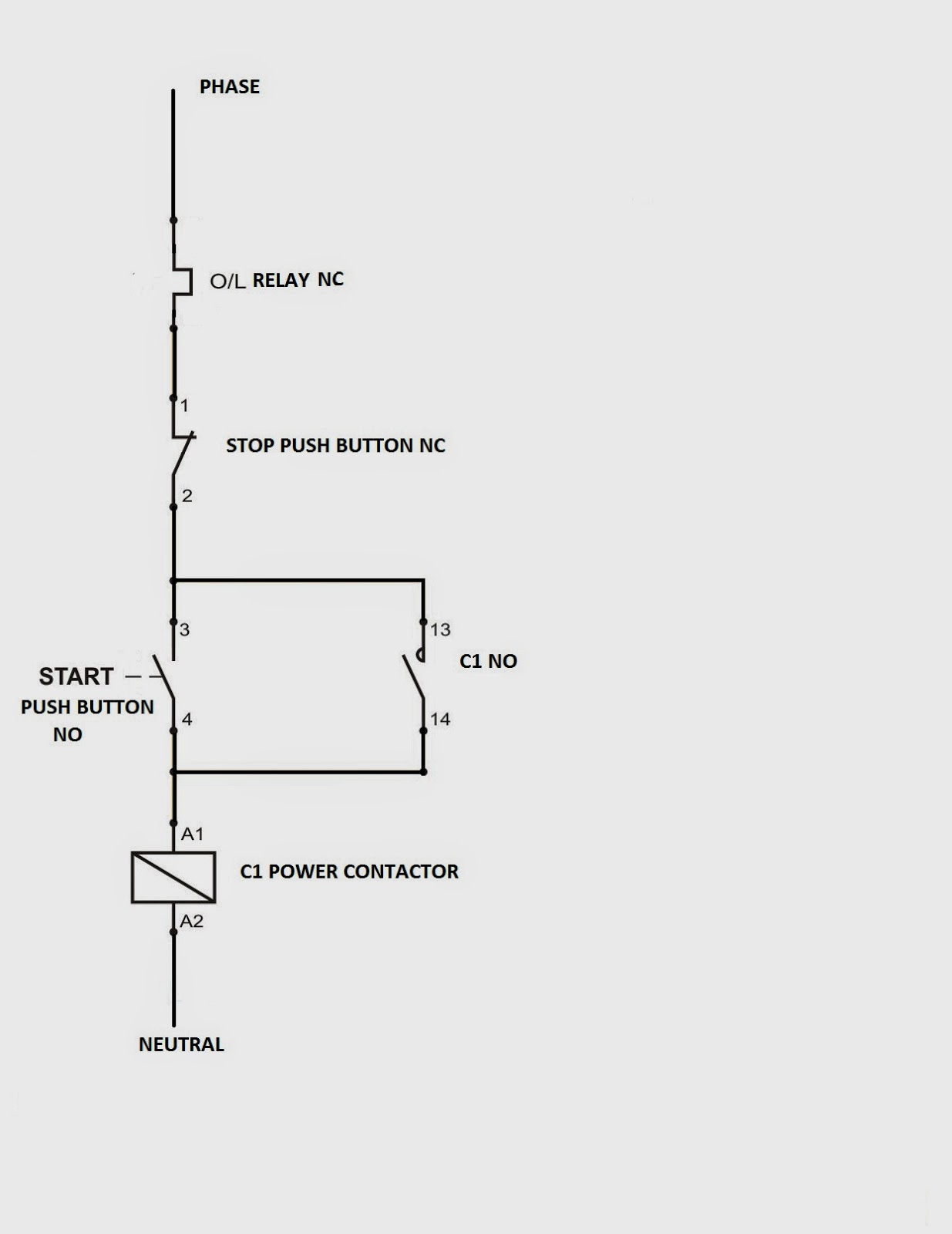
Here, you can see in the above diagram the coil of the contactor(a1 terminal) is connected through the nc contact of the overload relay. Thermal overload relay reset adjustment instructions generally, the red button on the front of the device is the stop button, and the blue button is the reset button. This directs the current through from l2 and directs it through the 3 rd phase on the contactor and overload l3 t3. If not, the arrangement won’t function as it ought to be. Wiring diagram contactor and overload wiring diagram technic contactor relay wiring wiring diagram datasource.
Source: stylesgurus.com
Product selection accessories din rail and panel mounting adapter these adapters are required when Dol starter control and power wiring by using a fuse, contactor, overload relay, motor. There are two popular types o/l relay which is thermal overload relay and electronic overload relay. So when the overload relay got tripped, its nc contact becomes open so the coil of the contactor will be disconnected from the power supply, hence the contactor will be turned off and disconnect the main power supply to the load. Thermal overload relays electronic overload relays.
 Source: interiorcommunicationselectrician.tpub.com
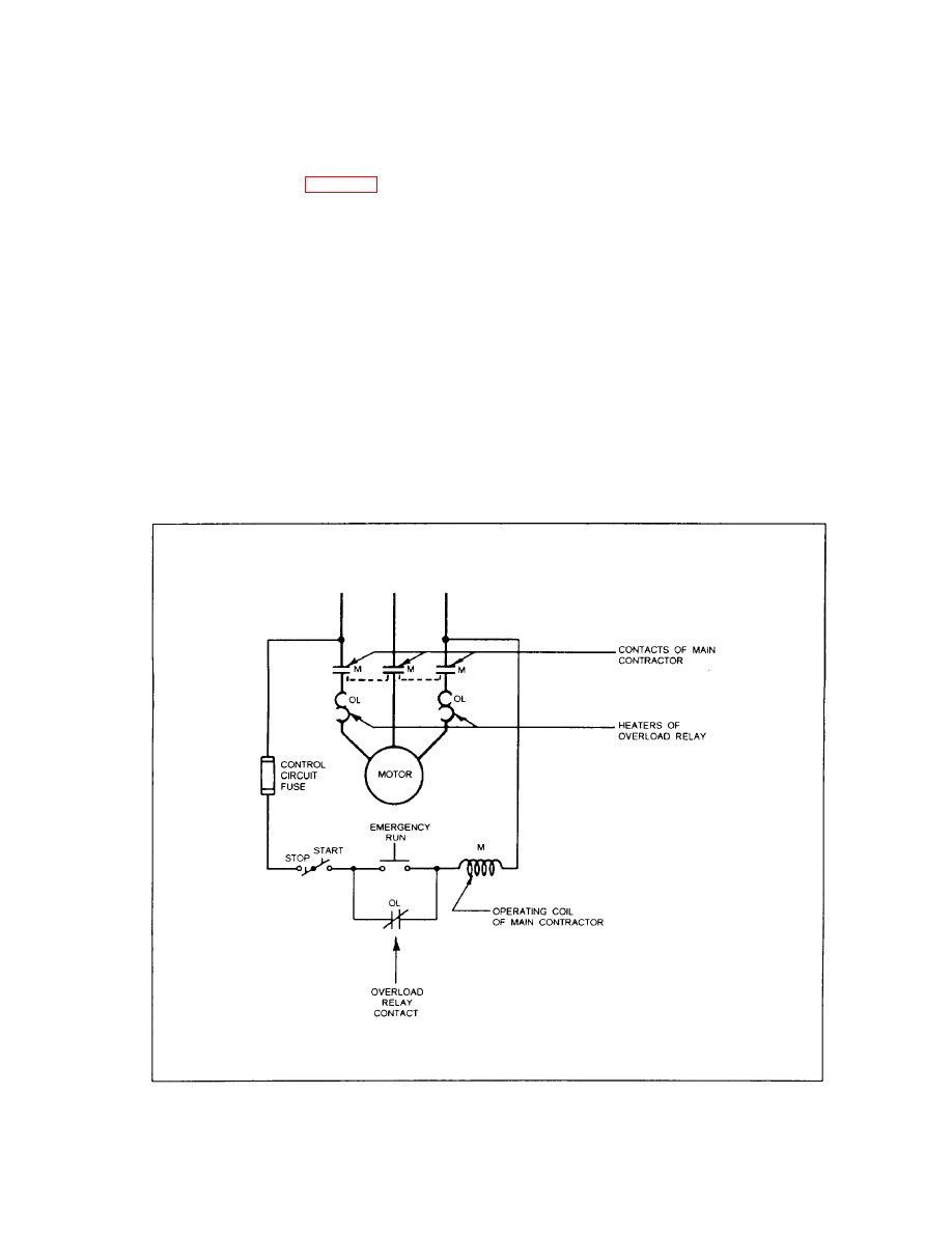
Product selection accessories din rail and panel mounting adapter these adapters are required when Terminal markings corresponding to those shown on the diagrams will be found on each switch. Then wire the overload relay with mc. The reset adjustment method of thermal overload relay can be. Variety of 2 pole contactor wiring diagram.
 Source: wiring89.blogspot.com
† e3 plus overload relay when features and/or functions apply specifically to it. Thermal overload relay reset adjustment instructions generally, the red button on the front of the device is the stop button, and the blue button is the reset button. Wiring diagram contactor and overload wiring diagram technic contactor relay wiring wiring diagram datasource. Sst 002 98 sb 7386 sb 7361 ptm 91 6566 sst 098 98. Contactor and thermal overload relay wiring diagram.
 Source: yourelectricalguide.com
Trip class setting and ground fault activation; Relays — thermal overload factory modifications c306 thermal overload relays with mounting adapter consists of a thermal overload relay mounted to a terminal base adapter — permits fast and easy installation. Copeland single phase compressor wiring diagram; There are two popular types o/l relay which is thermal overload relay and electronic overload relay. Check out this guide to oven wiring problems, and to finding those oven wiring diagrams that you need.
This site is an open community for users to submit their favorite wallpapers on the internet, all images or pictures in this website are for personal wallpaper use only, it is stricly prohibited to use this wallpaper for commercial purposes, if you are the author and find this image is shared without your permission, please kindly raise a DMCA report to Us.
If you find this site convienient, please support us by sharing this posts to your own social media accounts like Facebook, Instagram and so on or you can also save this blog page with the title thermal overload relay wiring diagram by using Ctrl + D for devices a laptop with a Windows operating system or Command + D for laptops with an Apple operating system. If you use a smartphone, you can also use the drawer menu of the browser you are using. Whether it’s a Windows, Mac, iOS or Android operating system, you will still be able to bookmark this website.
Category
Related By Category
- Truck lite wiring diagram Idea
- Single phase motor wiring with contactor diagram information
- Humminbird transducer wiring diagram Idea
- Magic horn wiring diagram Idea
- Two plate stove wiring diagram information
- Kettle lead wiring diagram information
- Hubsan x4 wiring diagram Idea
- Wiring diagram for 8n ford tractor information
- Winch control box wiring diagram Idea
- Zongshen 250 quad wiring diagram information