Tach wiring diagram Idea
Home » Trending » Tach wiring diagram Idea
Your Tach wiring diagram images are available in this site. Tach wiring diagram are a topic that is being searched for and liked by netizens now. You can Download the Tach wiring diagram files here. Find and Download all royalty-free images.
If you’re searching for tach wiring diagram images information related to the tach wiring diagram topic, you have visit the ideal blog. Our site always provides you with suggestions for seeing the highest quality video and image content, please kindly hunt and locate more informative video articles and graphics that match your interests.
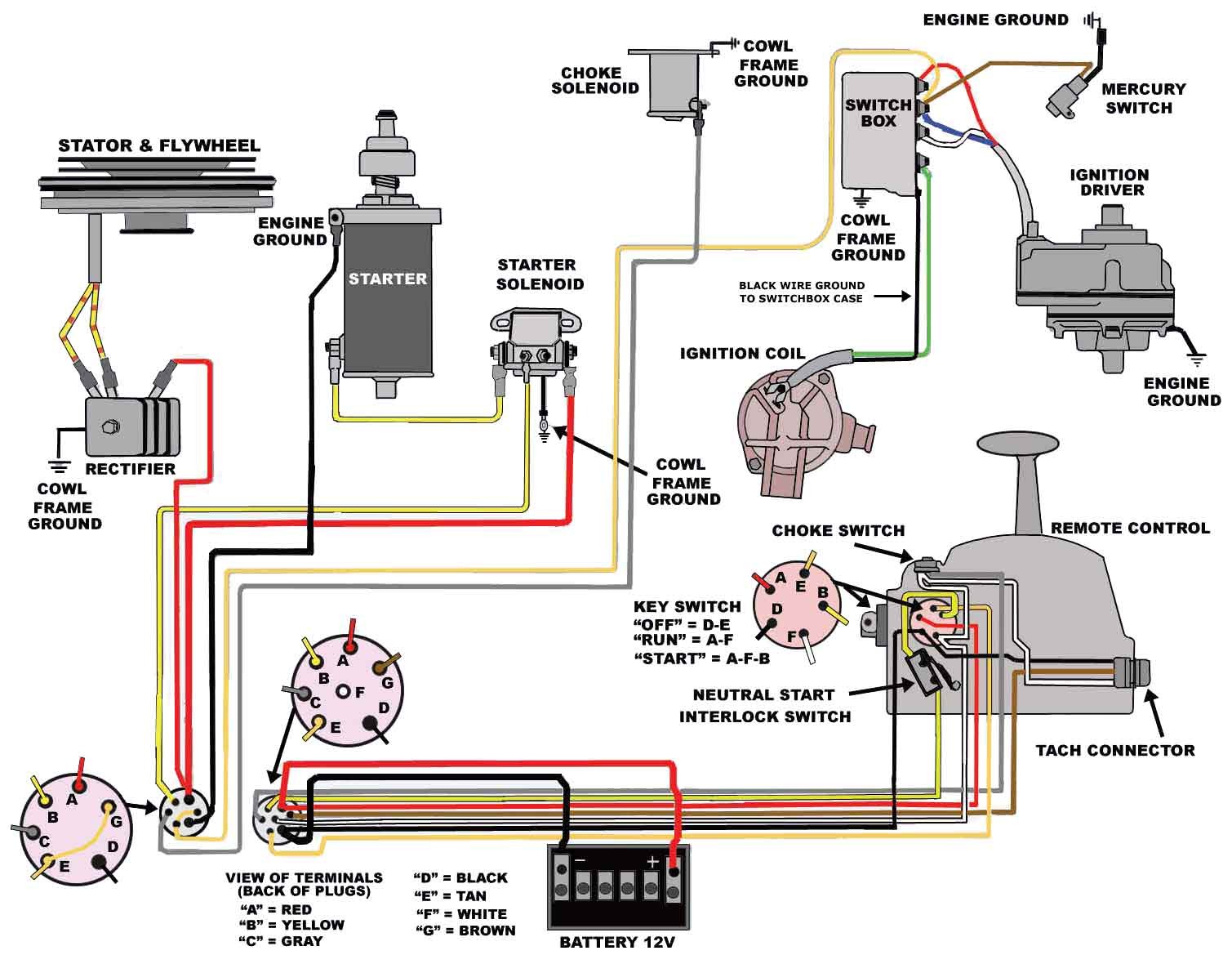
Tach Wiring Diagram. Tachometer wiring excerpt of 123gt diagram 1800. Please understand that proper wiring must be maintained throughout your vehicle. At times, the wires will cross. There are two things that will be found in any sun super tach 2 wiring diagram.
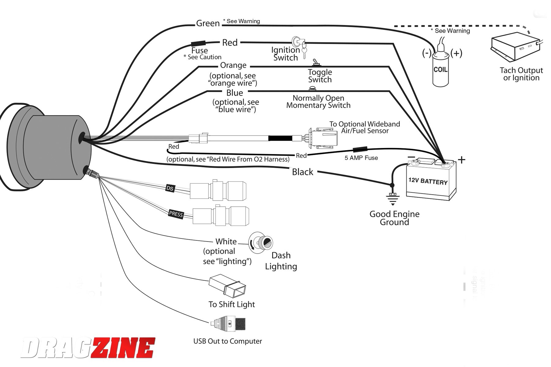 Autometer Pro Comp Tach Wiring Diagram Collection From dentistmitcham.com
Omc system check tach wiring diagram. Injunction of two wires is usually indicated by black dot on the intersection of 2 lines. I have a 3 wire aftermarket tach that has ambiguously worded wiring directions. They work great if they are wired right. When connecting to the negative post of the ignition coil or to the msd 6 box run the shielded cablešincluded with. The plug i have plugged to my check gauge adn there are two here is an omc system check wiring harness diagram.
Another thing that you will find a circuit diagram would be traces.
A switched +12 or 24 volt wire can be found coming from the ignition switch. Beginning with the tachometer, fig. Wiring connect the tachometer wires as shown. The wiring diagram shown is a typical installation. Omc system check tach wiring diagram. The tach must be returned to autometer for a light replacement.
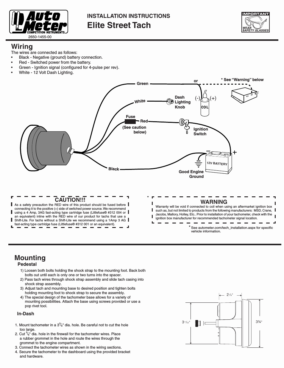 Source: annawiringdiagram.com
You may also mount the tachometer the installation, wiring, calibration and operation of all. You will be able to learn precisely when the assignments ought to be finished, which makes it easier for you to properly control your time. A wiring diagram is a simplified traditional pictorial depiction of an electrical circuit. For operation on 4 or 6 cylinder engines, a switch adjustment must be made. It consists of guidelines and diagrams for various types of wiring techniques as well as other items like lights, home windows, etc.
 Source: spiyda.com
A switched +12 or 24 volt wire can be found coming from the ignition switch. When connecting to the negative post of the ignition coil or to the msd 6 box run the shielded cablešincluded with. Tachometer wiring installing hood tachs motorola tachometer wiring diagram steering wheel diagram sun tach wiring diagram tachometer. 21628160 volvo penta evc tachometer 4000rpm. A circuit is generally composed by many components.
 Source: remajagilasempoi.blogspot.com
At times, the wires will cross. Please understand that proper wiring must be maintained throughout your vehicle. Components of sunpro tach wiring diagram and some tips. Tachometer wiring excerpt of 123gt diagram 1800. There are two things that will be found in any sun super tach 2 wiring diagram.
 Source: ricardolevinsmorales.com
The wiring diagram shown is a typical installation. Mallory super mag 3 wiring diagram from wiringall.com. I searched through several older threads on dixco tach, looking for a schematic for the internal wiring, and discovered many guess�s and. You may also mount the tachometer the installation, wiring, calibration and operation of all. Volvo penta tachometer 23715875 was 873992 and 23715874 873998 replaces vp873688 vp873660.
 Source: ricardolevinsmorales.com
Refer to diagram b for dimensions. For operation on 4 or 6 cylinder engines a switch adjustment must be made. Wiring connect the tachometer wires as shown. The below diagram shows how to wire a tachometer in an automotive application. Volvo wiring diagram disappointment nay anger sailnet community.
 Source: strawberry-sweet.blogspot.com
There are two things that will be found in any sun super tach 2 wiring diagram. Wiring connect the tachometer wires as shown. Variety of autometer tach wiring diagram. I searched through several older threads on dixco tach, looking for a schematic for the internal wiring, and discovered many guess�s and. You will be able to learn precisely when the assignments ought to be finished, which makes it easier for you to properly control your time.
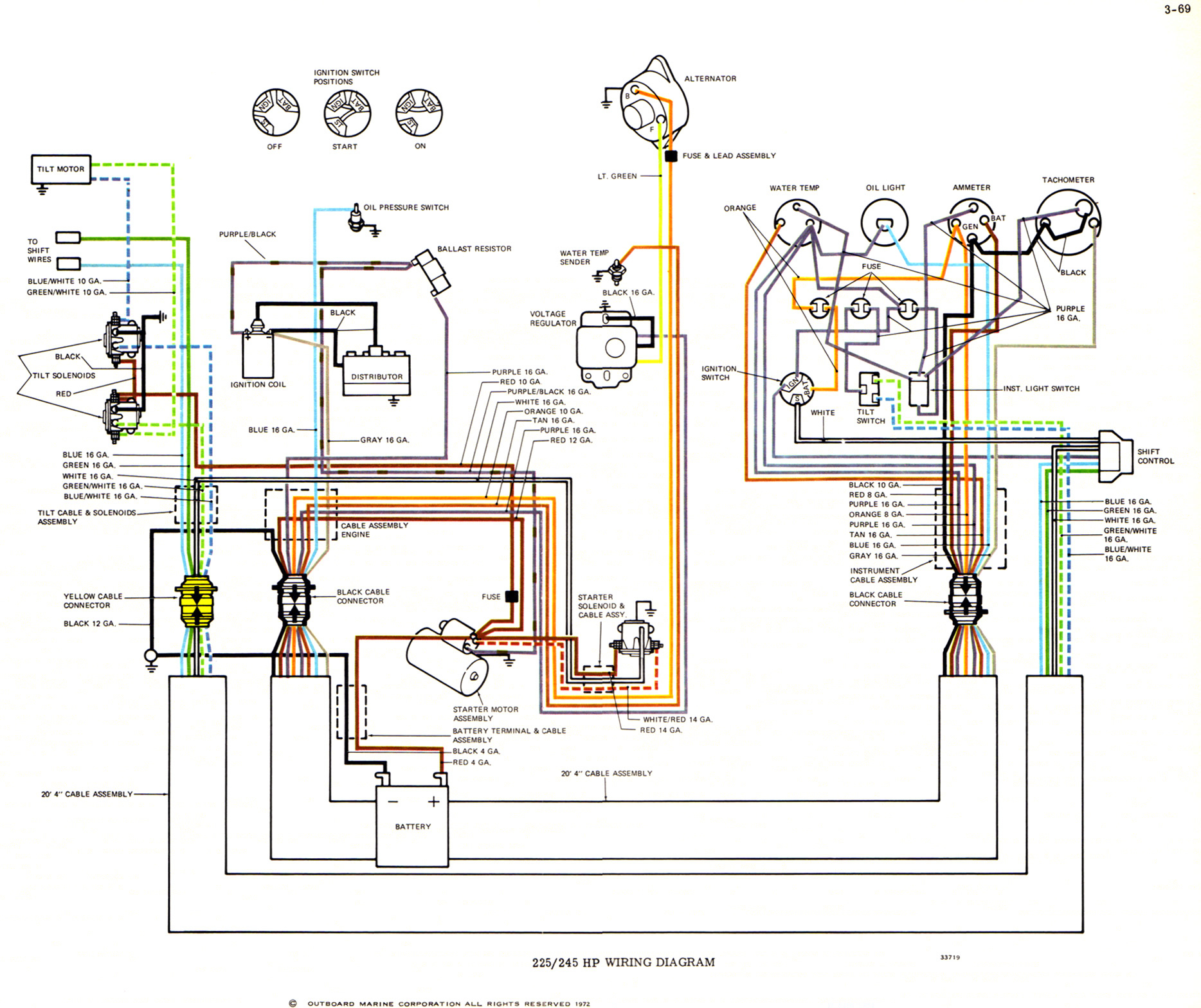 Source: 2020cadillac.com
Variety of autometer tach wiring diagram. Follow this wire to a junction, and attach the wire from pin. The other thing that you will discover a. Wiring diagram contains several detailed illustrations that present the relationship of varied things. Wiring diagram contains several detailed illustrations that present the relationship of varied things.
 Source: ricardolevinsmorales.com
Set the cylinder switches to match the number of cylinders in your engine. Cut out a notch in this grommet to pass the wires through or drill a new hole for the wires to be sent. You may also mount the tachometer the installation, wiring, calibration and operation of all. The wiring diagram shown is a typical installation. For operation on 4 or 6 cylinder engines a switch adjustment must be made.
 Source: ricardolevinsmorales.com
This can be helpful for the two the individuals and for specialists who are looking for more information on how to set up a working surroundings. Wiring configuration is different than most tachometers.20150213 200330 about press copyright contact us creators advertise developers terms privacy policy & safety how. Tachometer wiring excerpt of 123gt diagram 1800. The below diagram shows how to wire a tachometer in an automotive application. The first element is emblem that indicate electric component from the circuit.
![[DIAGRAM] 2 Stroke Yamaha Tach Wiring Diagram FULL Version [DIAGRAM] 2 Stroke Yamaha Tach Wiring Diagram FULL Version](https://ezgiresortotel.netlify.app/img/placeholder.svg)
For operation on 4 or 6 cylinder engines a switch adjustment must be made. Variety of autometer tach wiring diagram. A circuit is usually composed by many components. The tach must be returned to autometer for a light replacement. Set the cylinder switches to match the number of cylinders in your engine.
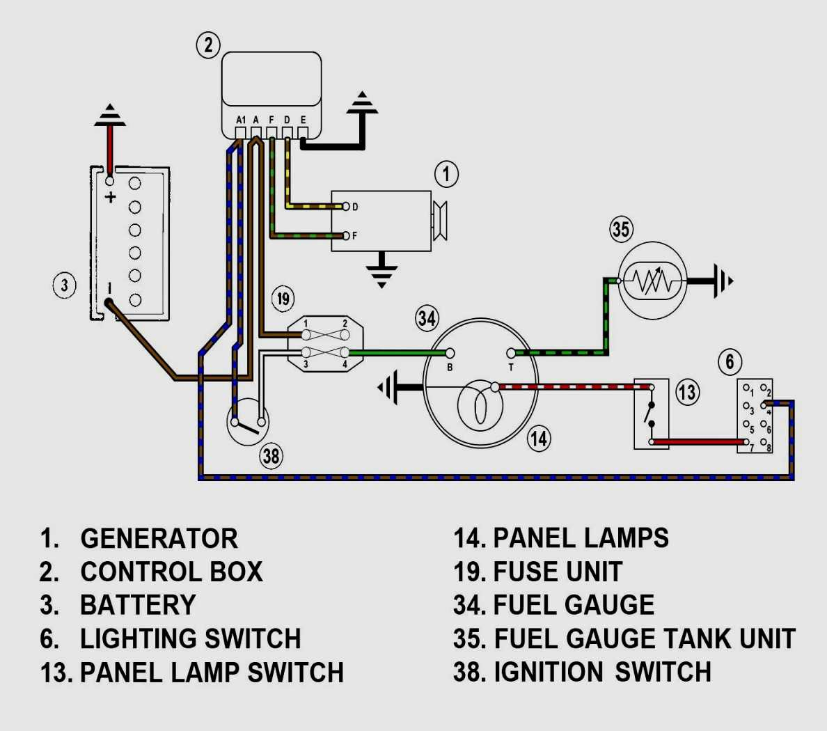 Source: annawiringdiagram.com
The first component is symbol that indicate electric element in the circuit. Make sure all wires are long enough to reach the necessary positive and negative terminals and any wires from the sensor. A circuit is usually composed by many components. However, it does not imply connection between the wires. Don™t coil up excess tachometer wires during installation.
 Source: wiringdiagrammechanic.blogspot.com
Don™t coil up excess tachometer wires during installation. Wiring configuration is different than most tachometers.20150213 200330 about press copyright contact us creators advertise developers terms privacy policy & safety how. Please understand that proper wiring must be maintained throughout your vehicle. The other thing that you will discover a. Here is how to wire the chinese digital tachometer.

They work great if they are wired right. Cut out a notch in this grommet to pass the wires through or drill a new hole for the wires to be sent. The other thing that you will discover a. 21628160 volvo penta evc tachometer 4000rpm. The first element is emblem that indicate electric component from the circuit.
 Source: stickerdeals.net
As stated earlier, the lines in a autometer tach wiring diagram represents wires. My issue is with the green signal wire. The diagram provides visual representation of the electrical arrangement. It consists of guidelines and diagrams for various types of wiring techniques as well as other items like lights, home windows, etc. Injunction of two wires is usually indicated by black dot on the junction of 2 lines.
 Source: dentistmitcham.com
The wiring diagram shown is a typical installation. The other thing that you will discover a. The tach must be returned to autometer for a light replacement. Component location of volvo tad734ge engine. Follow this wire to a junction, and attach the wire from pin.
![[DIAGRAM] Proform Tachometer Wiring Diagram FULL Version [DIAGRAM] Proform Tachometer Wiring Diagram FULL Version](http://www.rccinnovations.com/Temp/6768tach.jpg) Source: schematic.grundschulelaufeld.de
Source: schematic.grundschulelaufeld.de
Omc system check tach wiring diagram. Connect the wire from pin #4 to a switched +12 volt or +24 volt source. The first component is symbol that indicate electric element in the circuit. Omc system check tach wiring diagram. A switched +12 or 24 volt wire can be found coming from the ignition switch.
 Source: faceitsalon.com
When connecting to the negative post of the ignition coil or to the msd 6 box run the shielded cablešincluded with. The tach must be returned to autometer for a light replacement. Variety of autometer tach wiring diagram. There are just two things which are going to be present in any sunpro tach wiring diagram. Wire the tachometer to the vehicle as shown in diagram h on page 4.
 Source: tops-stars.com
This makes the process of assembling circuit simpler. Please understand that proper wiring must be maintained throughout your vehicle. Tachometer wiring installing hood tachs motorola tachometer wiring diagram steering wheel diagram sun tach wiring diagram tachometer. As stated earlier, the lines in a autometer tach wiring diagram represents wires. This tachometer is factory calibrated for 8 cylinder engines.
This site is an open community for users to do sharing their favorite wallpapers on the internet, all images or pictures in this website are for personal wallpaper use only, it is stricly prohibited to use this wallpaper for commercial purposes, if you are the author and find this image is shared without your permission, please kindly raise a DMCA report to Us.
If you find this site beneficial, please support us by sharing this posts to your own social media accounts like Facebook, Instagram and so on or you can also save this blog page with the title tach wiring diagram by using Ctrl + D for devices a laptop with a Windows operating system or Command + D for laptops with an Apple operating system. If you use a smartphone, you can also use the drawer menu of the browser you are using. Whether it’s a Windows, Mac, iOS or Android operating system, you will still be able to bookmark this website.
Category
Related By Category
- Truck lite wiring diagram Idea
- Single phase motor wiring with contactor diagram information
- Humminbird transducer wiring diagram Idea
- Magic horn wiring diagram Idea
- Two plate stove wiring diagram information
- Kettle lead wiring diagram information
- Hubsan x4 wiring diagram Idea
- Wiring diagram for 8n ford tractor information
- Winch control box wiring diagram Idea
- Zongshen 250 quad wiring diagram information