T1 wiring diagram Idea
Home » Trend » T1 wiring diagram Idea
Your T1 wiring diagram images are ready. T1 wiring diagram are a topic that is being searched for and liked by netizens today. You can Get the T1 wiring diagram files here. Find and Download all royalty-free vectors.
If you’re looking for t1 wiring diagram pictures information linked to the t1 wiring diagram keyword, you have pay a visit to the right blog. Our site always provides you with hints for refferencing the maximum quality video and picture content, please kindly surf and find more informative video content and graphics that match your interests.
T1 Wiring Diagram. Wiring diagrams show the connections to the controller. 1979 cb400 t1 wiring diagram (b&w) if this is your first visit, be sure to check out the faq. Wiring label t119s h224 c mog 24hfn1 mt0w. Wiring label t121s h218 c mof 18hfn1 mu0w.
T1 Wiring Diagram Wiring Diagram From alohagrace.blogspot.com
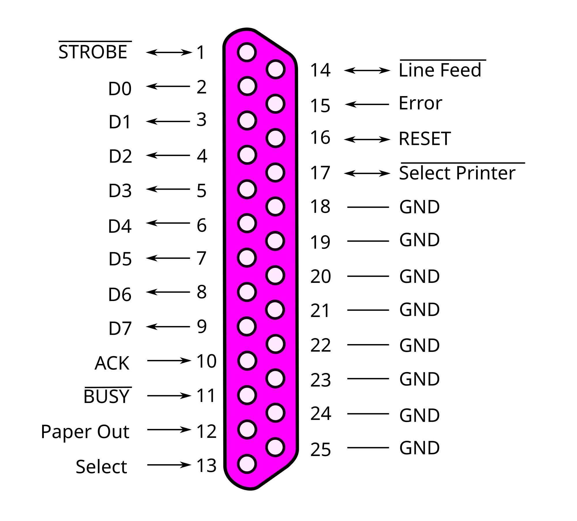
For replacement wires use conductors suitable for 105 c. Not suitable on systems that exceed 150 volts to ground. Dc thermostat wiring diagram pdf (dc_thermostat_2175.pdf) download. Pin outs for t1 cable and cross over cable t1 cable can be a rj48 or a simple rj 8 pin depending on the correct wiring L1 and l2, for example, imply that the motor voltage may be 240 volts. Please contact your local electrical contractor.
Wiring diagrams show the connections to the controller.
Wiring label t1 os218 ew ms11m 18hrfn1 mw0w. Wiring a wall thermostat for your heater follow the instructions below and the diagrams. T1e1j1 schematron.org t1 cables use four wires: Smart jacks come in many different shapes, sizes and styles; Wiring diagram includes numerous detailed illustrations that display the connection of varied items. Wiring label t121s h218 c mof 18hfn1 mu0w.
 Source: schematron.org
Open the diagram on your computer with an image program; See the variants page for more options. 5 hot water heat with power open zone valve. Streamlined backshop services provides dcc (digital command control) wiring multiple speakers to a decoder. All wiring must conform to local and national codes.
 Source: wiring03.blogspot.com
Smart jacks come in many different shapes, sizes and styles; These guidelines will likely be easy to comprehend and use. Please contact your local electrical contractor. Wiring label t121s h218 c mof 18hfn1 mu0w. Follow all local, city and national electric codes.
 Source: schematicdiagram37.blogspot.com
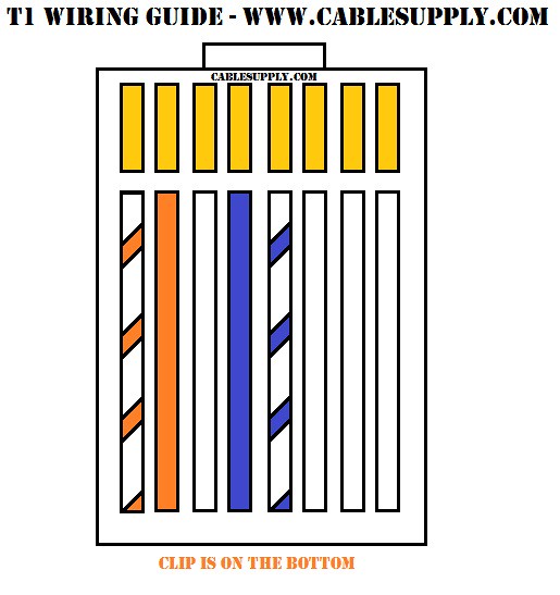
L1 and l2, for example, imply that the motor voltage may be 240 volts. Wiring diagram comes with numerous easy to adhere to wiring diagram directions. T1/e1/j1 rj48 cable diagram the following illustration provides the wiring connections for straight or crossover cables. The fundamental frame of t1 is shown in figure 2. Smart jacks come in many different shapes, sizes and styles;
 Source: pinterest.com
The fundamental frame of t1 is shown in figure 2. T4 and t1 pro wiring diagrams. Do not use t3 for any single phase loads. Wiring label t119s h224 e ms11m 24hrdn1 mt0w. Wiring label t121s h218 c mof 18hfn1 mu0w.
 Source: wiringdiagram.2bitboer.com
For supply connections use copper conductors only. G used for independent fan control only. L1 and l2, for example, imply that the motor voltage may be 240 volts. You need a cd light on the wic before you proceed with turning up a circuit. Wiring diagrams show the connections to the controller.
 Source: hestiahelper.blogspot.com
They can be used as a guide when wiring the controller. T4 and t1 pro wiring diagrams. Do not use t3 for any single phase loads. Wiring label t125s h109 c moz 09hfn1 bw0w. T1 and t4 shall be assigned to the main winding and t5 and t8 to the auxiliary winding (if present) with the polarity arrangement such that the standard direction of rotation is obtained if t4 and t5 are joined to one line and t1 and t8 to the other.* the terminal marking arrangement is shown diagrammatically in fig.
 Source: kovodym.blogspot.com
They can be wall mount single units or banks like the one depicted in the diagram above. Streamlined backshop services provides dcc (digital command control) wiring multiple speakers to a decoder. G used for independent fan control only. For supply connections use copper conductors only. Pin outs for t1 cable and cross over cable t1 cable can be a rj48 or a simple rj 8 pin depending on the correct wiring
 Source: arcelect.com
For supply connections use copper conductors only. Wiring diagrams show the connections to the controller. Disconnect all power before servicing. Smart jacks come in many different shapes, sizes and styles; Usually has a built in csu/dsu.
 Source: schematron.org
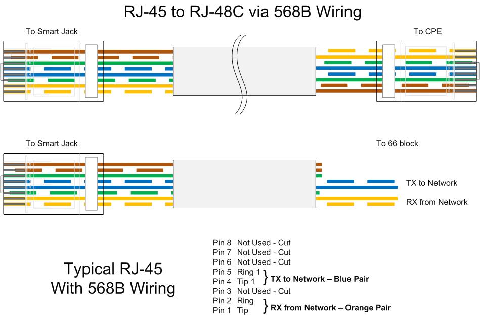
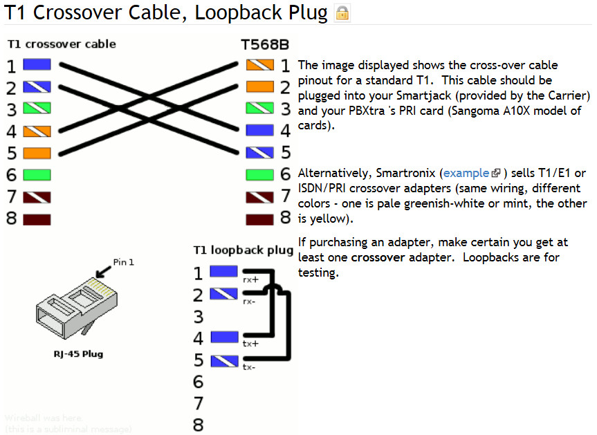
T4 and t1 pro wiring diagrams. Gas or oil furnace 1 stage cool only c g w r 1h/1c: Wiring label t119s h224 c mog 24hfn1 mt0w. In the end the white/blue and blue pair of wires is your transmit ring and tip and the white/orange and orange pair of wires is your receive ring and tip. T1/e1/j1 rj48 cable diagram the following illustration provides the wiring connections for straight or crossover cables.
 Source: hestiahelper.blogspot.com
G used for independent fan control only. G used for independent fan control only. Wiring diagrams for l1 and l2 motors the l symbol denotes the line, or the incoming circuit wires that supply electricity to the motor. The my4n dc 24 s is a miniature power relay with dc coil. Wiring label t119s h224 c mog 24hfn1 mt0w.
Source: diagrammaticlymcoq.senologiainfo.it
T4 and t1 pro wiring diagrams wiring diagrams 1 stage heat only: Wiring label t125s h109 e ms11m 09hrfn1 bx5w. In the end the white/blue and blue pair of wires is your transmit ring and tip and the white/orange and orange pair of wires is your receive ring and tip. L1 and l2, for example, imply that the motor voltage may be 240 volts. The fundamental frame of t1 is shown in figure 2.
 Source: hestiahelper.blogspot.com
Wiring label t121s h218 c mof 18hfn1 mu0w. We�re working on a short tutorial looking at dcc decoder installation in older locomotives, such as lima and hornby, that are powered by. Wiring label t123s h112 c moz 12hfn1 bw0w. T1e1j1 schematron.org t1 cables use four wires: All wiring must conform to local and national codes.
 Source: tops-stars.com
You have to register before you can post: Thermostat wiring diagram doesn t show t1 and t2 but i figure that to be the 2 wires that they. Two for the transmit signal and two for the receive. Usually has a built in csu/dsu. T4 and t1 pro wiring diagrams wiring diagrams 1 stage heat only:
Source: alohagrace.blogspot.com
The fundamental frame of t1 is shown in figure 2. 5 hot water heat with power open zone valve. Wiring diagrams for l1 and l2 motors the l symbol denotes the line, or the incoming circuit wires that supply electricity to the motor. They show the relative location of the components. For supply connections use copper conductors only.
 Source: hestiahelper.blogspot.com
They show the relative location of the components. Mercedes t1 wiring diagram, related gallery: 5 hot water heat with power open zone valve. Pin outs for t1 cable and cross over cable t1 cable can be a rj48 or a simple rj 8 pin depending on the correct wiring You need a cd light on the wic before you proceed with turning up a circuit.
Source: fjelloghjem.blogspot.com
1 phase, high and low voltage 1 phase 3 phase note: After registration, you will be emailed a link to validate your registration. T4 and t1 pro wiring diagrams wiring diagrams 1 stage heat only: Wiring label t123s h112 c moz 12hfn1 bw0w. Wiring diagram comes with numerous easy to adhere to wiring diagram directions.
 Source: flickr.com
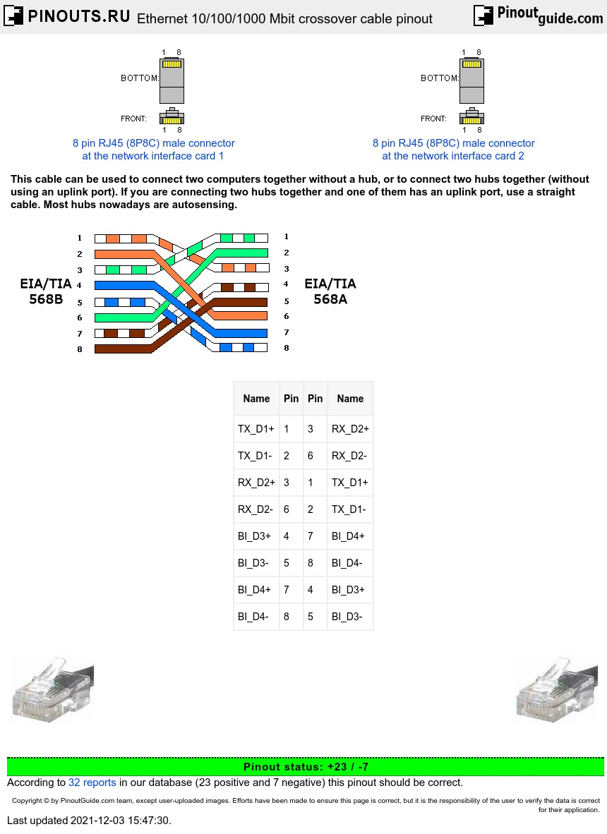
Not suitable on systems that exceed 150 volts to ground. Wiring label t123s h112 c moz 12hfn1 bw0w. 6 hot water heat with power open/power closed, series 20 zone valve. They show the relative location of the components. In some network applications, the equipment is so close together that a crossover.
 Source: schematron.org
Wiring label t119s h224 e ms11m 24hrdn1 mt0w. Wiring a wall thermostat for your heater follow the instructions below and the diagrams. Wiring label t123s h112 c moz 12hfn1 bw0w. Open the diagram on your computer with an image program; Some of the fuse boxes pictured in the diagrams are rotated 180 degrees from how they actually mount in the car:
This site is an open community for users to submit their favorite wallpapers on the internet, all images or pictures in this website are for personal wallpaper use only, it is stricly prohibited to use this wallpaper for commercial purposes, if you are the author and find this image is shared without your permission, please kindly raise a DMCA report to Us.
If you find this site adventageous, please support us by sharing this posts to your favorite social media accounts like Facebook, Instagram and so on or you can also bookmark this blog page with the title t1 wiring diagram by using Ctrl + D for devices a laptop with a Windows operating system or Command + D for laptops with an Apple operating system. If you use a smartphone, you can also use the drawer menu of the browser you are using. Whether it’s a Windows, Mac, iOS or Android operating system, you will still be able to bookmark this website.
Category
Related By Category
- Predator 670 engine wiring diagram Idea
- Frsky x8r wiring diagram information
- Pioneer ts wx130da wiring diagram Idea
- Johnson 50 hp wiring diagram Idea
- Kohler voltage regulator wiring diagram Idea
- Johnson 50 hp outboard wiring diagram information
- Kti hydraulic remote wiring diagram Idea
- Pyle plpw12d wiring diagram information
- Tx9600ts wiring diagram information
- Lifan 50cc wiring diagram information