T1 line wiring diagram Idea
Home » Trend » T1 line wiring diagram Idea
Your T1 line wiring diagram images are available in this site. T1 line wiring diagram are a topic that is being searched for and liked by netizens now. You can Get the T1 line wiring diagram files here. Get all royalty-free photos.
If you’re searching for t1 line wiring diagram images information related to the t1 line wiring diagram keyword, you have come to the right site. Our website frequently provides you with hints for viewing the maximum quality video and image content, please kindly hunt and find more informative video content and graphics that fit your interests.
T1 Line Wiring Diagram. Wiring diagram line we are make source the schematics, wiring diagrams and technical photos. Wires to the components and terminals of the controller. Always use wiring diagram supplied on motor nameplate. Lines — l1, l3 l1, l3 l1 t1 l2 t2 l3 t3 alphanumeric, corresponding to incoming line and motor terminal designations no specific marking no standard.
 T1/E1, T3/E3, and OC3/STM1 requirements From infoproducts.alcatel-lucent.com
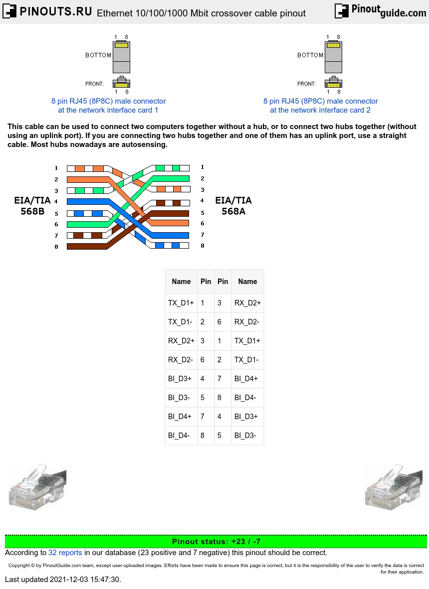
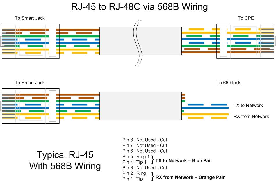
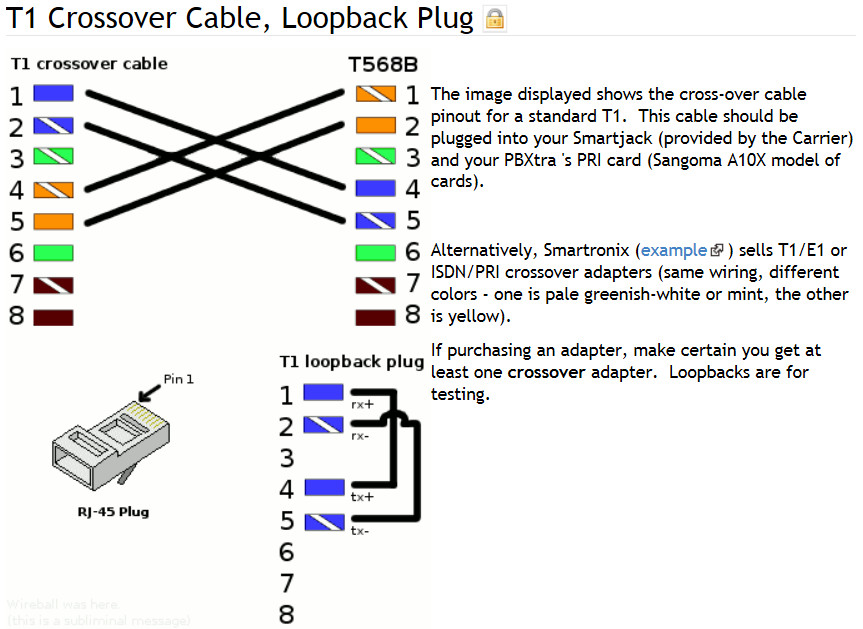
Wiring diagram line we are make source the schematics, wiring diagrams and technical photos. Basics 8 aov elementary & block diagram : Symbols are electrical representation only. Two for the transmit signal and two for the receive. Pin outs for t1 cable and cross over cable. T1 100 ohms splitter patch panel do ethernet splitters slow down connection quora 2pcs rj45 1 to 2 female lan network cable divider adapter at affordable s free shipping real.
Most heat only, gas or oil forced air systems do not use a fan (g) wire.
All wiring must be done by a licensed electrician. Electrical symbols and line diagrams chapter 3 material taken from chapter 3 of electric motor controls, g. Mercedes t1 wiring diagram, related gallery: This is supported through 2 and 4 wire e & m (ear and mouth) signalling techniques through the t1 mux. Lines — l1, l3 l1, l3 l1 t1 l2 t2 l3 t3 alphanumeric, corresponding to incoming line and motor terminal designations no specific marking no standard. Two for the transmit signal and two for the receive.
 Source: hestiahelper.blogspot.com
Mercedes t1 wiring diagram, related gallery: G used for independent fan control only. Weg 3 phase motor wiring diagram tagged weg motor wiring diagram phase motor. Basics 9 4.16 kv pump schematic : All wiring must be done by a licensed electrician.
 Source: hestiahelper.blogspot.com
Gas or oil furnace 1 stage cool only c g w r 1h/1c: The dol starter joints the 3 phase main wiring with the induction motor namely l1, l2 and l3 when the start. All wiring must be done by a licensed electrician. Symbols are electrical representation only. Square d 2601 aw2 3 phase wiring diagram | 2002 ford f250 wiring schematic | electrical circuit diagram explanation | pll block diagram pdf | wiring diagram for 7 blade trailer plug | 3 phase wiring in home | electrical wire for house.
 Source: pinterest.com
Dimmer switch wiring diagram l1 l2 from www.lightwiring.co.uk. I’m going to start by explaining some of the basics of t1 wiring, discuss some relevant terminology, and pepper in some of my own experience throughout that might help your troubleshooting. All wiring must be done by a licensed electrician. Some of the fuse boxes pictured in the diagrams are. What is l1 and l2 on a wiring diagram?

Ethernet cable splitter wiring diagram wiring diagram line wiring diagram. Wires to the components and terminals of the controller. I’m going to start by explaining some of the basics of t1 wiring, discuss some relevant terminology, and pepper in some of my own experience throughout that might help your troubleshooting. In models vfc063p, vfc084p, vfc100p, vfc200p, and vfc300p the thermal protector is in direct line with the power to the motor windings. In such case each cable will be marked with the.
 Source: schematron.org
This is supported through 2 and 4 wire e & m (ear and mouth) signalling techniques through the t1 mux. Gas or oil furnace 1 stage cool only c g w r 1h/1c: Depending on the correct wiring. L1 (line 1) is a red wire and l2. T1 t2 t3 2/ 4/ 6/ separate control remove wire “c” if supplied and connect separate control lines to the number 1 terminal on the remote pilot device and to the number 96 terminal on the overload relay l1 l2 l3 5 reverse 5 4 2 5 s.p.d.t.
 Source: pinterest.com
G used for independent fan control only. Air flow rates and for use of line lengths over 15 feet. The voltage between two lines (for example �l1� and �l2�) is called the line to line (or phase to phase) voltage. They can be used as a guide when wiring the controller. Mercedes t1 wiring diagram, related gallery:
 Source: fryguy.net
T1 t3 t2 yel/pnk blu/pnk yel/ blu brn/yel *hps blu/pnk cont 11 21 23 23 schematic diagram (ladder form) l1 *sr *sc h comp *st c f cap l2 5 2 1 *lps * ctd *dts *lls ifr thermostat indoor y g r r c external power. If a thermal overload occurs, the. T1 100 ohms splitter patch panel do ethernet splitters slow down connection quora 2pcs rj45 1 to 2 female lan network cable divider adapter at affordable s free shipping real. Gas or oil furnace 1 stage cool only c g w r 1h/1c: Air flow rates and for use of line lengths over 15 feet.
 Source: hestiahelper.blogspot.com
2 wire or 4 wire? Basics 10 480 v pump schematic : Depending on the correct wiring. T1 lines carry mbps signals for computer network connections in the immediate area, across town or across the country. In such case each cable will be marked with the.
 Source: hestiahelper.blogspot.com
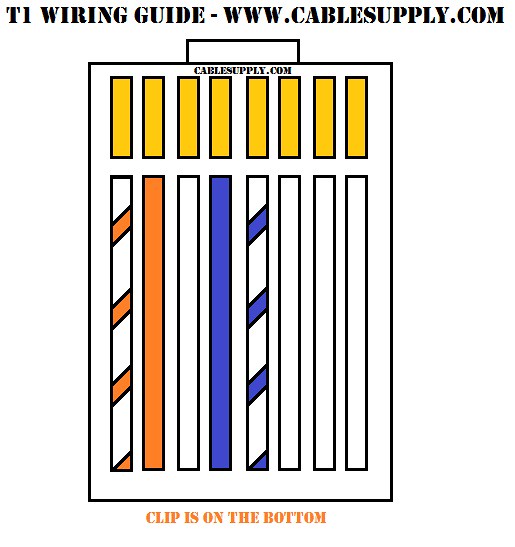
Air flow rates and for use of line lengths over 15 feet. The coil of the contactor is 380 vac. In such case each cable will be marked with the. Always use wiring diagram supplied on motor nameplate. T1 cables use four wires:
 Source: wiringdiagram.2bitboer.com
Electrical symbols and line diagrams chapter 3 material taken from chapter 3 of electric motor controls, g. The dol starter joints the 3 phase main wiring with the induction motor namely l1, l2 and l3 when the start. I’m going to start by explaining some of the basics of t1 wiring, discuss some relevant terminology, and pepper in some of my own experience throughout that might help your troubleshooting. All wiring must be done by a licensed electrician. L1 (line 1) is a red wire and l2.
 Source: flickr.com
Right click on the diagram/key/fuse box you want to download. Depending on the correct wiring. Bold lines denote the power circuit and thin lines are used to show the control circuit. The motors wiring diagram on the underside of the junction box is badly faded, part of it reads t1 & t2 are the ***at leads . The voltage between two lines (for example �l1� and �l2�) is called the line to line (or phase to phase) voltage.
 Source: frostburg.edu
The motors wiring diagram on the underside of the junction box is badly faded, part of it reads t1 & t2 are the ***at leads . T1 t3 t2 yel/pnk blu/pnk yel/ blu brn/yel *hps blu/pnk cont 11 21 23 23 schematic diagram (ladder form) l1 *sr *sc h comp *st c f cap l2 5 2 1 *lps * ctd *dts *lls ifr thermostat indoor y g r r c external power. In some network applications, the equipment is so close together that a crossover cable just a. All wiring must be done by a licensed electrician. Each lead may have one or more cables comprising that lead.
 Source: schematron.org
Pin outs for t1 cable and cross over cable. Gas or oil furnace 1 stage cool only c g w r 1h/1c: If a thermal overload occurs, the. Simply so, what is l1 in wiring? This connection uses an rj45 connector.
 Source: infoproducts.alcatel-lucent.com
Most heat only, gas or oil forced air systems do not use a fan (g) wire. The voltage between two lines (for example �l1� and �l2�) is called the line to line (or phase to phase) voltage. T4 and t1 pro wiring diagrams wiring diagrams 1 stage heat only: Black wires are conventionally used in power circuits and red wire in control circuits for ac magnetic. Symbols are electrical representation only.
 Source: hestiahelper.blogspot.com
Basics 9 4.16 kv pump schematic : I’m going to start by explaining some of the basics of t1 wiring, discuss some relevant terminology, and pepper in some of my own experience throughout that might help your troubleshooting. Mercedes t1 wiring diagram, related gallery: The motors wiring diagram on the underside of the junction box is badly faded, part of it reads t1 & t2 are the ***at leads . Right click on the diagram/key/fuse box you want to download.
 Source: bohack.com
The wiring of direct on line control circuit starter is following: T1 t3 t2 yel/pnk blu/pnk yel/ blu brn/yel *hps blu/pnk cont 11 21 23 23 schematic diagram (ladder form) l1 *sr *sc h comp *st c f cap l2 5 2 1 *lps * ctd *dts *lls ifr thermostat indoor y g r r c external power. Typical wiring diagram line diagrams show circuits of the operation of the controller. Almost 99% of the time if there is an issue with a t1, its because of the wiring. T1+t6+t7+t12 t2+t4+t8+t10 t3+t5+t9+t 12 lead.
 Source: arcelect.com
G used for independent fan control only. Open the diagram on your computer with an image program. This connection uses an rj45 connector. T1 100 ohms splitter patch panel do ethernet splitters slow down connection quora 2pcs rj45 1 to 2 female lan network cable divider adapter at affordable s free shipping real. Here is a basic wiring static phase converter diagram.

Some of the fuse boxes pictured in the diagrams are. In a 4 wire t1 configuration only 2 pr are used blu/bluwht and ong/ongwht. Clearly the intended use of t1 was to bring in as many telephone lines using voice as possible through a digitized technique (pcm pulse code modulation). If a thermal overload occurs, the. T1 cable can be a rj48 or a simple rj 8 pin.
This site is an open community for users to share their favorite wallpapers on the internet, all images or pictures in this website are for personal wallpaper use only, it is stricly prohibited to use this wallpaper for commercial purposes, if you are the author and find this image is shared without your permission, please kindly raise a DMCA report to Us.
If you find this site good, please support us by sharing this posts to your own social media accounts like Facebook, Instagram and so on or you can also save this blog page with the title t1 line wiring diagram by using Ctrl + D for devices a laptop with a Windows operating system or Command + D for laptops with an Apple operating system. If you use a smartphone, you can also use the drawer menu of the browser you are using. Whether it’s a Windows, Mac, iOS or Android operating system, you will still be able to bookmark this website.
Category
Related By Category
- Predator 670 engine wiring diagram Idea
- Frsky x8r wiring diagram information
- Pioneer ts wx130da wiring diagram Idea
- Johnson 50 hp wiring diagram Idea
- Kohler voltage regulator wiring diagram Idea
- Johnson 50 hp outboard wiring diagram information
- Kti hydraulic remote wiring diagram Idea
- Pyle plpw12d wiring diagram information
- Tx9600ts wiring diagram information
- Lifan 50cc wiring diagram information