System sensor rts151key wiring diagram Idea
Home » Trending » System sensor rts151key wiring diagram Idea
Your System sensor rts151key wiring diagram images are available in this site. System sensor rts151key wiring diagram are a topic that is being searched for and liked by netizens now. You can Find and Download the System sensor rts151key wiring diagram files here. Download all free photos and vectors.
If you’re looking for system sensor rts151key wiring diagram images information linked to the system sensor rts151key wiring diagram topic, you have come to the ideal site. Our website always gives you suggestions for seeking the maximum quality video and image content, please kindly search and find more informative video articles and images that fit your interests.
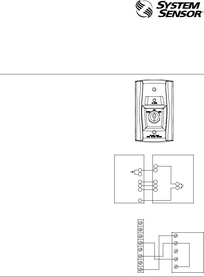
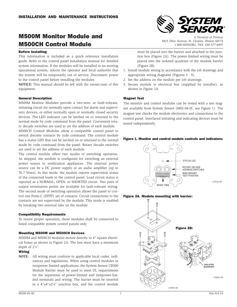
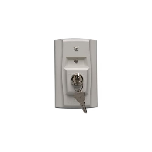
System Sensor Rts151key Wiring Diagram. Consult the appropriate detector installation instructions for the applicable wiring diagram. System sensor’s rts151 is an automatic fire detector accessory designed to test a remotely located detector. In canadian applications, the rts151key(a) is intended to be located in the same room as the smoke detector and within 60 feet of the unit. This unit senses smoke in the most challenging conditions operating in airflow speeds of 100 to 4000 feet per.
![[DIAGRAM] Apollo S65 Smoke Detector Wiring Diagram FULL [DIAGRAM] Apollo S65 Smoke Detector Wiring Diagram FULL](https://ricardolevinsmorales.com/wp-content/uploads/2018/09/system-sensor-smoke-detector-wiring-diagram-gst-conventional-smoke-detector-wiring-diagram-addressable-fire-and-16k.jpg) [DIAGRAM] Apollo S65 Smoke Detector Wiring Diagram FULL From xyzprintingwiring.leschikoulades.fr
[DIAGRAM] Apollo S65 Smoke Detector Wiring Diagram FULL From xyzprintingwiring.leschikoulades.fr
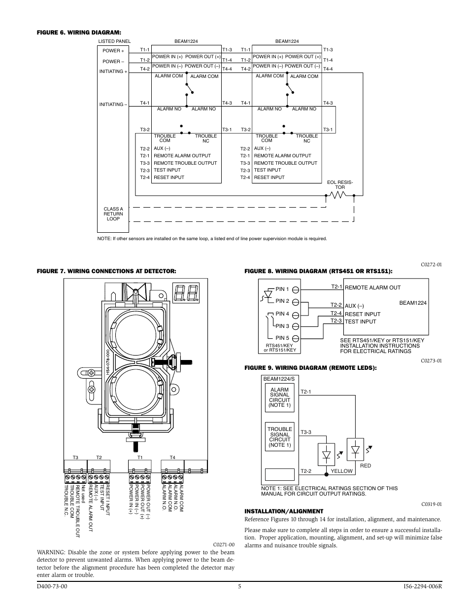
System sensor rts451 wiring diagram. Until it stops and led turns off. In canadian applications, the rts151key(a) is intended to be located in the same room as the smoke detector and within 60 feet of the unit. Wiring diagram for rts151key a to d4120 4 wire duct smoke detector. It shall be capable of local testing via magnetic switch or remote testing using the rts151key remote test. Smoke detectors designed for use in air duct systems are used to sense the presence of smoke in the duct.
19 20 15 2 6 1 5 4 3 rts451key(a) d4120 (green led) power (red led) alarm field.
Before working on the system, notify the proper authorities that the system is undergoing maintenance and will be temporarily out of service. If a system control panel is used, the panel itself may require testing. The rts151key mounts to a single gang box (2 1/2˝ minimum depth), or directly to the wall or ceiling. Before working on the system, notify the proper authorities that the system is undergoing maintenance and will be temporarily out of service. The creators will not be held accountable for any unintentional flaws or omissions that may be found. See figure 8 for wiring diagram of rts151 with duct smoke detectors.
 Source: tops-stars.com
Diagram psl 2000 smoke detector wiring diagram full version hd quality wiring diagram beakersdiagrammed aube siae fr. Ok, i have this solar panel i was given, and a knex motor without a battery box, and in need to test which wire is positive and which is negative on the solar panel. See figure 8 for wiring diagram of rts151 with duct smoke detectors. Consult the appropriate detector installation instructions for the applicable wiring diagram. The rts151key mounts to a single gang box (2 1/2˝ minimum depth), or directly to the wall or ceiling.
 Source: firealarm.com
Wiring diagram for rts151key a to d4120 4 wire duct smoke detector. All wiring must be installed in accordance with local requirements. Diagram psl 2000 smoke detector wiring diagram full version hd quality wiring diagram beakersdiagrammed aube siae fr. Read system sensor rts151key wiring diagram pdf on our digital library. Consult detector installation instructions for additional information.
![[DIAGRAM] Apollo S65 Smoke Detector Wiring Diagram FULL [DIAGRAM] Apollo S65 Smoke Detector Wiring Diagram FULL](https://ricardolevinsmorales.com/wp-content/uploads/2018/09/system-sensor-smoke-detector-wiring-diagram-gst-conventional-smoke-detector-wiring-diagram-addressable-fire-and-16k.jpg) Source: xyzprintingwiring.leschikoulades.fr
Source: xyzprintingwiring.leschikoulades.fr
Diagram psl 2000 smoke detector wiring diagram full version hd quality wiring diagram beakersdiagrammed aube siae fr. In canadian applications, the rts151key(a) is intended to be located in the same room as the smoke detector and within 60 feet of the unit. Wiring diagram for rts151key a to d4120 4 wire duct smoke detector. Duct smoke detector online from elcodis, view and download d4240 pdf datasheet, diodes, rectifiers specifications. The rts151key mounts to a single gang box (2 1 2 ˝ minimum depth), or directly to the wall or ceiling.
 Source: manualmachine.com
Smoke detectors designed for use in air duct systems are used to sense the presence of smoke in the duct. Green indicates power and that the detector board is in place. System sensor rts451 wiring diagram. The writers of system sensor rts151key wiring diagram have made all reasonable attempts to offer latest and precise information and facts for the readers of this publication. The rts151key system sensor mounts to a single gang box (2 1 /2˝ minimum depth), or directly to the wall or ceiling.
Source: hyperikon-wiring-diagram.blogspot.com
• the use of either the rts151 or rts151key. Consult detector installation instructions for additional information. Rts151key a remote test station system sensor System sensor rts151key installation and maintenance instructions. The rts151key system sensor mounts to a single gang box (2 1 /2˝ minimum depth), or directly to the wall or ceiling.
 Source: hestiahelper.blogspot.com
15 20 2 11 2 alarm signal 1 aux. In canadian applications, the rts151key is intended to be located in the same room as the smoke detector and within 60 feet of the unit. Read system sensor rts151key wiring diagram pdf on our digital library. The system sensor rts451key(a) is an automatic fire detector accessory designed to test remotely located duct and beam detectors. System sensor rts151key installation and maintenance instructions.
 Source: alohagrace.blogspot.com
See figure 8 for wiring diagram of rts151 with duct smoke detectors. 19 20 15 2 6 1 5 4 3 rts451key(a) d4120 (green led) power (red led) alarm field. Wiring instructions consult the appropriate detector installation instructions for the applicable wiring diagram. The rts151key system sensor mounts to a single gang box 2 1 2 minimum depth or directly to the wall or ceiling. The rts151key mounts to a single gang box (2 1 2 ˝ minimum depth), or directly to the wall or ceiling.
Source: alohagrace.blogspot.com
Ok, i have this solar panel i was given, and a knex motor without a battery box, and in need to test which wire is positive and which is negative on the solar panel. See figure 8 for wiring diagram of rts151 with duct smoke detectors. • the use of either the rts151 or rts151key. Consult detector installation instructions for additional information. System sensor rts151key installation and maintenance instructions.
 Source: manualsdir.com
Until it stops and led turns off. System sensor’s rts151 is an automatic fire detector accessory designed to test a remotely located detector. Smoke detectors designed for use in air duct systems are used to sense the presence of smoke in the duct. 19 20 15 2 6 1 5 4 3 rts451key(a) d4120 (green led) power (red led) alarm field. Wiring diagram for rts151key a to d4120 4 wire duct smoke detector.
 Source: manualsdir.com
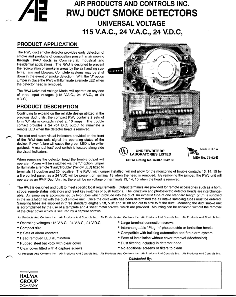
Consult the appropriate detector installation instructions for the applicable wiring diagram. Consult the appropriate detector installation instructions for the applicable wiring diagram. Duct smoke detector online from elcodis, view and download d4240 pdf datasheet, diodes, rectifiers specifications. Green indicates power and that the detector board is in place. This unit senses smoke in the most challenging conditions operating in airflow speeds of 100 to 4000 feet per.
 Source: manualsdir.com
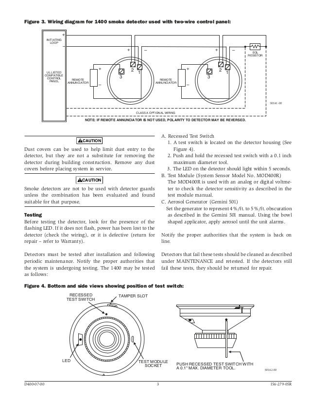
System sensor smoke detector wiring diagram system sensor convention 4 wire duct smoke detector d4120 wiring fancy. Wiring instructions consult the appropriate detector installation instructions for the applicable wiring diagram. In canadian applications, the rts151key is intended to be located in the same room as the smoke detector and within 60 feet of the unit. The system sensor rts451key(a) is an automatic fire detector accessory designed to test remotely located duct and beam detectors. If a system control panel is used, the panel itself may require testing.
 Source: jemsecurity.com
In canadian applications, the rts151key(a) is intended to be located in the same room as the smoke detector and within 60 feet of the unit. System sensor rts451 wiring diagram. Consult detector installation instructions for additional information. The rts151 system sensor mounts to a single gang box (2 1/2” minimum depth), or directly to the wall or ceiling. The rts151key mounts to a single gang box (2 1/2˝ minimum depth), or directly to the wall or ceiling.
 Source: hestiahelper.blogspot.com
The system sensor rts451key(a) is an automatic fire detector accessory designed to test remotely located duct and beam detectors. Model d4120 and d4s duct smoke detectors utilize 4 wire photoelectric tech nology for the detection of smoke. This unit senses smoke in the most challenging conditions operating in airflow speeds of 100 to 4000 feet per. • the use of either the rts151 or rts151key. Rts151key system sensor keyed remote test & reset station
 Source: controlconsultantsinc.com
Read system sensor rts151key wiring diagram pdf on our digital library. This unit senses smoke in the most challenging conditions operating in airflow speeds of 100 to 4000 feet per. The rts151key system sensor mounts to a single gang box (2 1 /2˝ minimum depth), or directly to the wall or ceiling. The rts151key mounts to a single gang box (2 1/2˝ minimum depth), or directly to the wall or ceiling. System sensor rts451 wiring diagram.
 Source: how-small-can-words-be-tattooed-news.blogspot.com
Consult the appropriate detector installation instructions for the applicable wiring diagram. Green indicates power and that the detector board is in place. Consult the appropriate detector installation instructions for the applicable wiring diagram. Consult the appropriate detector installation instructions for the applicable wiring diagram. 19 20 15 2 6 1 5 4 3 rts451key(a) d4120 (green led) power (red led) alarm field.
 Source: alohagrace.blogspot.com
System wiring diagram for dnr: In canadian applications, the rts151key(a) is intended to be located in the same room as the smoke detector and within 60 feet of the unit. See figure 8 for wiring diagram of rts151 with duct smoke detectors. System sensor rts151key installation and maintenance instructions. All wiring must be installed in accordance with local requirements.
 Source: ebay.com
Wiring instructions consult the appropriate detector installation instructions for the applicable wiring diagram. The rts151key mounts to a single gang box (2 1/2˝ minimum depth), or directly to the wall or ceiling. See figure 8 for wiring diagram of rts151 with duct smoke detectors. In canadian applications, the rts151key is intended to be located in the same room as the smoke detector and within 60 feet of the unit. Ok, i have this solar panel i was given, and a knex motor without a battery box, and in need to test which wire is positive and which is negative on the solar panel.
 Source: airconint.com
System sensor rts451 wiring diagram. The rts151key mounts to a single gang box (2 1/2˝ minimum depth), or directly to the wall or ceiling. System sensor smoke detector wiring diagram system sensor convention 4 wire duct smoke detector d4120 wiring fancy. The creators will not be held accountable for any unintentional flaws or omissions that may be found. Rts151key a remote test station system sensor
This site is an open community for users to do sharing their favorite wallpapers on the internet, all images or pictures in this website are for personal wallpaper use only, it is stricly prohibited to use this wallpaper for commercial purposes, if you are the author and find this image is shared without your permission, please kindly raise a DMCA report to Us.
If you find this site good, please support us by sharing this posts to your preference social media accounts like Facebook, Instagram and so on or you can also save this blog page with the title system sensor rts151key wiring diagram by using Ctrl + D for devices a laptop with a Windows operating system or Command + D for laptops with an Apple operating system. If you use a smartphone, you can also use the drawer menu of the browser you are using. Whether it’s a Windows, Mac, iOS or Android operating system, you will still be able to bookmark this website.
Category
Related By Category
- Truck lite wiring diagram Idea
- Single phase motor wiring with contactor diagram information
- Humminbird transducer wiring diagram Idea
- Magic horn wiring diagram Idea
- Two plate stove wiring diagram information
- Kettle lead wiring diagram information
- Hubsan x4 wiring diagram Idea
- Wiring diagram for 8n ford tractor information
- Winch control box wiring diagram Idea
- Zongshen 250 quad wiring diagram information