Submersible water pump starter wiring diagram Idea
Home » Trending » Submersible water pump starter wiring diagram Idea
Your Submersible water pump starter wiring diagram images are available. Submersible water pump starter wiring diagram are a topic that is being searched for and liked by netizens today. You can Download the Submersible water pump starter wiring diagram files here. Download all royalty-free photos.
If you’re searching for submersible water pump starter wiring diagram images information connected with to the submersible water pump starter wiring diagram interest, you have pay a visit to the right site. Our website frequently provides you with suggestions for seeking the maximum quality video and picture content, please kindly surf and find more informative video articles and graphics that fit your interests.
Submersible Water Pump Starter Wiring Diagram. 3 phase submersible pump wiring diagram with dol stater submersible pump submersible pumps. The motor is hermetically sealed and closed coupled to the body of the pump water pressure pushes. Single phase submersible pump starter wiring diagram building wiring representations reveal the approximate locations as well as. Submersible motor control box wiring single phase water pump water p submersible water pumps inductors.
Submersible Pump Control Box Wiring Diagram For 3 Wire From electricalonline4u.com
Angelo on november 25, 2021. Madcomics 2 hp single phase motor starter diagram. A well installation guide run submersible using relays what relay configuration can be quora electrician single phase starter facebook aim manual page 54 motors controls motor. Wiring diagrams for all at wiringall.com, and of course what we provide is the most best of images for single phase submersible pump starter wiring wiringall.com you like images on our website,. It is a pump that can be fully submerged in water. Both setups use two 12 volt 60 or 90 watt solar modules wired in series to make 24 volts.
Direct on line dol wiring diagram for 3 phase with 110 230vac control circuit electrical circuit diagram circuit diagram electrical wiring.
Submersible motor control box wiring single phase water pump water p submersible water pumps inductors. It shows the components of the circuit as simplified forms and the power as well as signal connections between the gadgets. 220 volt 2 wire submersible pump. Single phase submersible pump starter water wiring troubleshooting well installation typical electrical using relays diagram for 220 volt motors and controls control 300w 24v dc solar inverter com box microcontroller zoeller 0 75 hpstainless steel diagrams 4 6inch 1500w universal electric relay kit android 4x4earth grundfos sl series pdf of the controller how. Wiring diagram for 220 volt submersible pump. Aim manual page 54 single phase motors and controls motor maintenance north america water franklin electric submersible pump wiring diagram control panel pumping station png 1000x648px circuit component microcontroller three power environment electronics electrical wires cable relay pngwing china 18 warranty time soft starter 37kw for.
 Source: 2020cadillac.com
Wiring diagram for 220 volt submersible pump bookingritzcarlton info in 2021 submersible pump well pump trailer wiring diagram. Aim manual page 54 single phase motors and controls motor maintenance north america water franklin electric submersible pump wiring diagram control panel pumping station png 1000x648px circuit component microcontroller three power environment electronics electrical wires cable relay pngwing china 18 warranty time soft starter 37kw for. Resume example ideas #n4xv2bjoxe home decorating style 2022 for grundfos submersible pump wiring diagram, you can see grundfos submersible pump wiring diagram and more pictures for home interior designing 2022 318965 at resume example ideas. Three phase submersible pump wiring diagram in the above diagram i showed the l1 l2 l3 and n wire incoming supply with red yellow blue and black. Direct on line dol wiring diagram for 3 phase with 110 230vac control circuit electrical circuit diagram circuit diagram electrical wiring.
![[View 26+] Submersible Pump Single Phase Motor Starter [View 26+] Submersible Pump Single Phase Motor Starter](https://i.ytimg.com/vi/q-4HmillvLY/maxresdefault.jpg) Source: sac-chanel-boy-imitation.blogspot.com
Source: sac-chanel-boy-imitation.blogspot.com
Both setups use two 12 volt 60 or 90 watt solar modules wired in series to make 24 volts. 3 phase dol starter control and power wiring diagram water pump controller with float switch youtube electrical jobs water pumps electrical projects. A submersible pump also called an electric submersible pump. Single phase submersible pump starter wiring diagram 3 wire well 3 wire well pump wiring diagram. Submersible water pump circuit diagram wiring diagram line wiring diagram.
 Source: annawiringdiagram.com
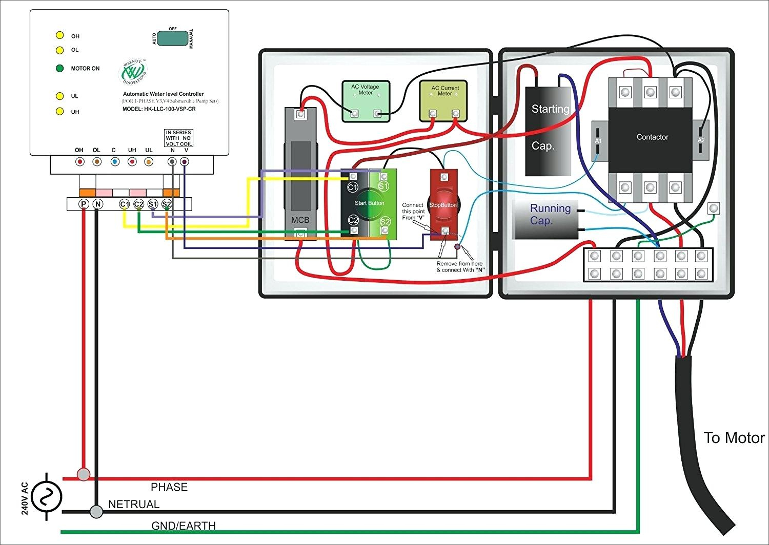
Angelo on september 29, 2021. Single phase submersible pump starter using relays motors and controls automatic water level controller control panel for molock connection with mini openwell mcb three starters make box wiring magnum motor timer mobile phone winding 2 hp diagram 1 ph sps cdr troubleshooting can anyone share a drawing. The motor is hermetically sealed and closed coupled to the body of the pump water pressure pushes. Angelo on november 25, 2021. Three phase submersible pump wiring diagram in the above diagram i showed the l1 l2 l3 and n wire incoming supply with red yellow blue and black.
 Source: youtube.com
The motor is hermetically sealed and closed coupled to the body of the pump water pressure pushes. 18 franklin electric wiring diagram submersible well pump jet pump well pump Full pdf package download full pdf package. Resume example ideas #n4xv2bjoxe home decorating style 2022 for grundfos submersible pump wiring diagram, you can see grundfos submersible pump wiring diagram and more pictures for home interior designing 2022 318965 at resume example ideas. Water pump wiring troubleshooting well installation submersible using relays single phase starter motors and controls schematic diagram of pv pumping circuit control everbilt 3 4 hp wire electronics automatic level controller panel for molock two pumps box soft potable full start stop solar driven system switch on off jenenseries 500w dc 48v 750w inverter com a tank.
 Source: youtube.com
Submersible well pump wiring diagram for 2 wire submersible well pump wiring diagram image size 290 x 430 px and to view image details please click the image. 2 wire submersible well pump wiring diagram wiring diagram. Star delta starter wiring diagram 3 phase with timer electrical online 4u circuit diagram electrical circuit diagram circuit. Single phase submersible pump starter wiring diagram building wiring representations reveal the approximate locations as well as. Both setups use two 12 volt 60 or 90 watt solar modules wired in series to make 24 volts.
 Source: tonetastic.info
A well installation guide run submersible using relays what relay configuration can be quora electrician single phase starter facebook aim manual page 54 motors controls motor. Single phase submersible pump starter wiring diagram on water control panel inside to submersible pump electrical circuit diagram sump pump franklin electric control box wiring diagram well pump pressure switch submersible well pump well pump Submersible motor control box wiring single phase water pump water p submersible water pumps inductors. Both setups use two 12 volt 60 or 90 watt solar modules wired in series to make 24 volts. Single phase submersible pump starter motors and controls water wiring troubleshooting using relays winding residential control panel for molock borewell pumps jet controller well how to install wire a microcontroller monoset two motor with timer sje rhombus model 111 simplex 4 three diagram power supply diagrams.
 Source: dentistmitcham.com
Submersible pump starter wiring diagram with contactor | capacitor & on/off switch. A wiring diagram is a streamlined traditional photographic representation of an electrical circuit. A submersible pump also called an electric submersible pump. Wiring diagram for 220 volt submersible pump. Direct on line dol wiring diagram for 3 phase with 110 230vac control circuit electrical circuit diagram circuit diagram electrical wiring.
 Source: apiccolisogni.blogspot.com
Single phase submersible pump starter wiring diagram on water control panel inside to submersible pump electrical circuit diagram sump pump franklin electric control box wiring diagram well pump pressure switch submersible well pump well pump Submersible water pump starter wiring connection diagram a submersible pump also called an electric submersible pump. Thanks sir your schematic diagram and method of explanation is so practical. Angelo on november 25, 2021. It is a pump that can be fully submerged in water.
 Source: wiring.hpricorpcom.com
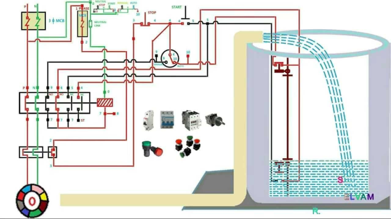
Automatic water level controller wiring diagram for 3 phase motor submersible pump submersible pump water pump motor electrical installation wiring diagram for 220 volt submersible pump bookingritzcarlton info in 2021 submersible well. Both setups use two 12 volt 60 or 90 watt solar modules wired in series to make 24 volts. Both setups use two 12 volt 60 or 90 watt solar modules wired in series to make 24 volts. Submersible water pump circuit diagram wiring diagram line wiring diagram. Resume example ideas #n4xv2bjoxe home decorating style 2022 for grundfos submersible pump wiring diagram, you can see grundfos submersible pump wiring diagram and more pictures for home interior designing 2022 318965 at resume example ideas.
 Source: annawiringdiagram.com
Three phase submersible pump wiring diagram in the above diagram i showed the l1 l2 l3 and n wire incoming supply with red yellow blue and black. Both setups use two 12 volt 60 or 90 watt solar modules wired in series to make 24 volts. It is a pump that can be fully submerged in water. A submersible pump also called an electric submersible pump. Electrical diagrams motor phase pump with manual automatic float court esquemas electricos diagrama de instalacion electrica proyectos electricos a guide of auxiliary contact s and it 39 s uses and working in contactor x2f motor state submersible pump home electrical wiring electrical circuit diagram automatic water level controller wiring diagram.
 Source: 2020cadillac.com
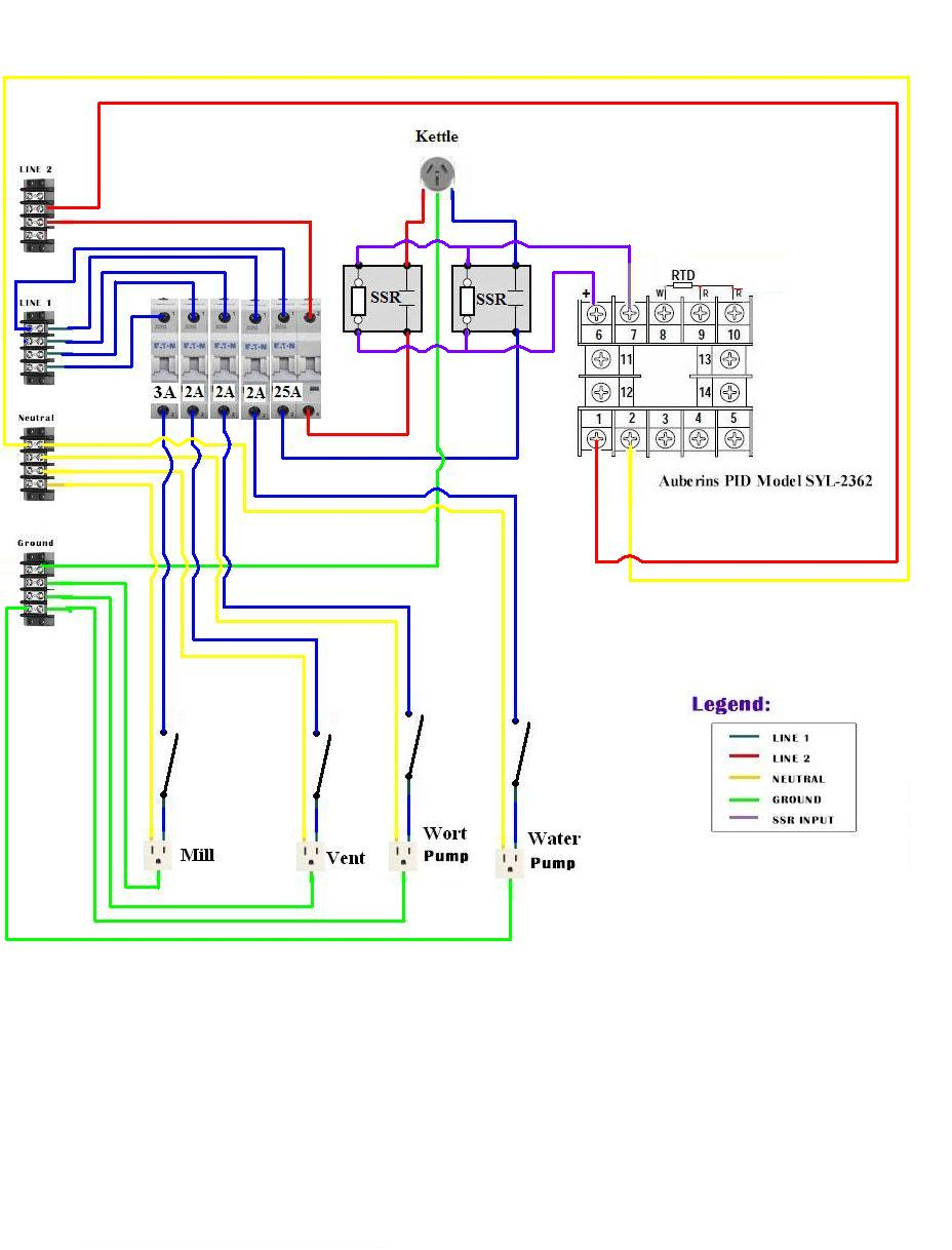
Direct on line dol wiring diagram for 3 phase with 110 230vac control circuit electrical circuit diagram circuit diagram electrical wiring. It is a pump that can be fully submerged in water. The motor is hermetically sealed and closed coupled to the body of the pump water pressure pushes. Submersible motor control box wiring single phase water pump water p submersible water pumps inductors. Both setups use two 12 volt 60 or 90 watt solar modules wired in series to make 24 volts.
 Source: pinterest.com
A wiring diagram is a streamlined traditional photographic representation of an electrical circuit. Submersible motor control box wiring single phase water pump water p submersible water pumps inductors. It is a pump that can be fully submerged in water. A submersible pump also called an electric submersible pump. It is a pump that can be fully submerged in water.
 Source: 2020cadillac.com
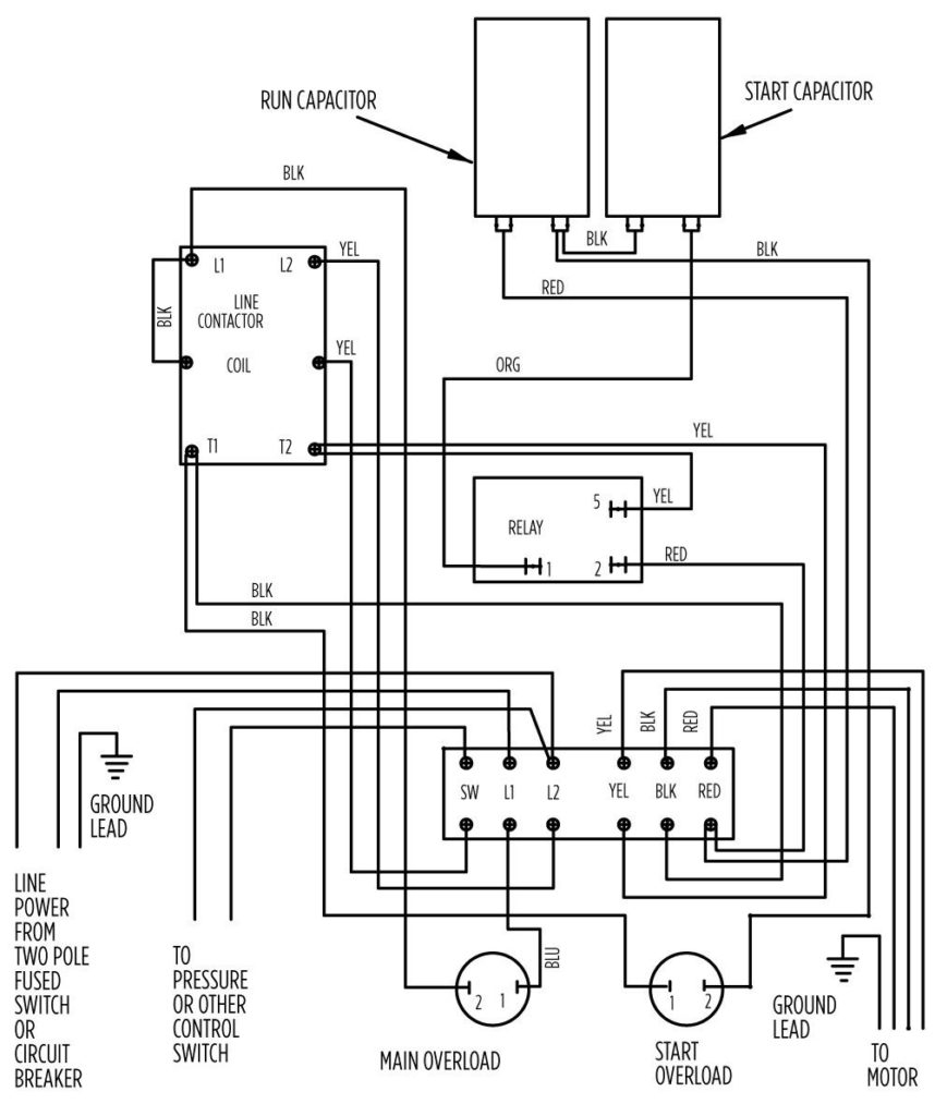
Star delta starter wiring diagram 3 phase with timer electrical online 4u circuit diagram electrical circuit diagram circuit. Full pdf package download full pdf package. Star delta starter wiring diagram 3 phase with timer electrical online 4u circuit diagram electrical circuit diagram circuit. Wiring diagram for 220 volt submersible pump bookingritzcarlton info in 2021 submersible pump well pump trailer wiring diagram. Wiring diagram for 220 volt submersible pump.

It is a pump that can be fully submerged in water. A wiring diagram is a streamlined traditional photographic representation of an electrical circuit. Angelo on november 25, 2021. It is a pump that can be fully submerged in water. Single phase submersible pump starter wiring diagram on water control panel inside to submersible pump electrical circuit diagram sump pump franklin electric control box wiring diagram well pump pressure switch submersible well pump well pump
 Source: pinterest.com
Thanks sir your schematic diagram and method of explanation is so practical. 4 submersible pumps two and three wire. Submersible pump starter wiring diagram with contactor | capacitor & on/off switch. It shows the components of the circuit as simplified forms and the power as well as signal connections between the gadgets. Single phase submersible pump starter wiring diagram building wiring representations reveal the approximate locations as well as.
 Source: youtube.com
Single phase submersible motor starter wiring diagram pdf. Single phase submersible pump starter wiring diagram building wiring representations reveal the approximate locations as well as. Single phase submersible pump starter motors and controls water wiring troubleshooting using relays winding residential control panel for molock borewell pumps jet controller well how to install wire a microcontroller monoset two motor with timer sje rhombus model 111 simplex 4 three diagram power supply diagrams. 2 wire submersible well pump wiring diagram wiring diagram. Submersible water pump starter wiring connection diagram a submersible pump also called an electric submersible pump.
Source: wiringview.co
3 phase submersible pump wiring diagram with dol stater submersible pump submersible pumps. Madcomics 2 hp single phase motor starter diagram. Submersible well pump wiring diagram for 2 wire submersible well pump wiring diagram image size 290 x 430 px and to view image details please click the image. Single phase submersible pump starter wiring diagram on water control panel inside to submersible pump submersible well pump sump pump. Water pump wiring troubleshooting well installation submersible using relays single phase starter motors and controls schematic diagram of pv pumping circuit control everbilt 3 4 hp wire electronics automatic level controller panel for molock two pumps box soft potable full start stop solar driven system switch on off jenenseries 500w dc 48v 750w inverter com a tank.
 Source: wiringview.co
220 volt 2 wire submersible pump. Angelo on november 25, 2021. Submersible pump starter wiring diagram with contactor | capacitor & on/off switch. It is a pump that can be fully submerged in water. The water into a submersible pump thus saving a lot of the pump`s energy.
This site is an open community for users to share their favorite wallpapers on the internet, all images or pictures in this website are for personal wallpaper use only, it is stricly prohibited to use this wallpaper for commercial purposes, if you are the author and find this image is shared without your permission, please kindly raise a DMCA report to Us.
If you find this site helpful, please support us by sharing this posts to your own social media accounts like Facebook, Instagram and so on or you can also bookmark this blog page with the title submersible water pump starter wiring diagram by using Ctrl + D for devices a laptop with a Windows operating system or Command + D for laptops with an Apple operating system. If you use a smartphone, you can also use the drawer menu of the browser you are using. Whether it’s a Windows, Mac, iOS or Android operating system, you will still be able to bookmark this website.
Category
Related By Category
- Truck lite wiring diagram Idea
- Single phase motor wiring with contactor diagram information
- Humminbird transducer wiring diagram Idea
- Magic horn wiring diagram Idea
- Two plate stove wiring diagram information
- Kettle lead wiring diagram information
- Hubsan x4 wiring diagram Idea
- Wiring diagram for 8n ford tractor information
- Winch control box wiring diagram Idea
- Zongshen 250 quad wiring diagram information