Stepper driver wiring diagram Idea
Home » Trending » Stepper driver wiring diagram Idea
Your Stepper driver wiring diagram images are available. Stepper driver wiring diagram are a topic that is being searched for and liked by netizens today. You can Download the Stepper driver wiring diagram files here. Download all free images.
If you’re searching for stepper driver wiring diagram images information linked to the stepper driver wiring diagram topic, you have come to the ideal blog. Our site frequently gives you hints for seeing the maximum quality video and image content, please kindly hunt and locate more informative video articles and images that match your interests.
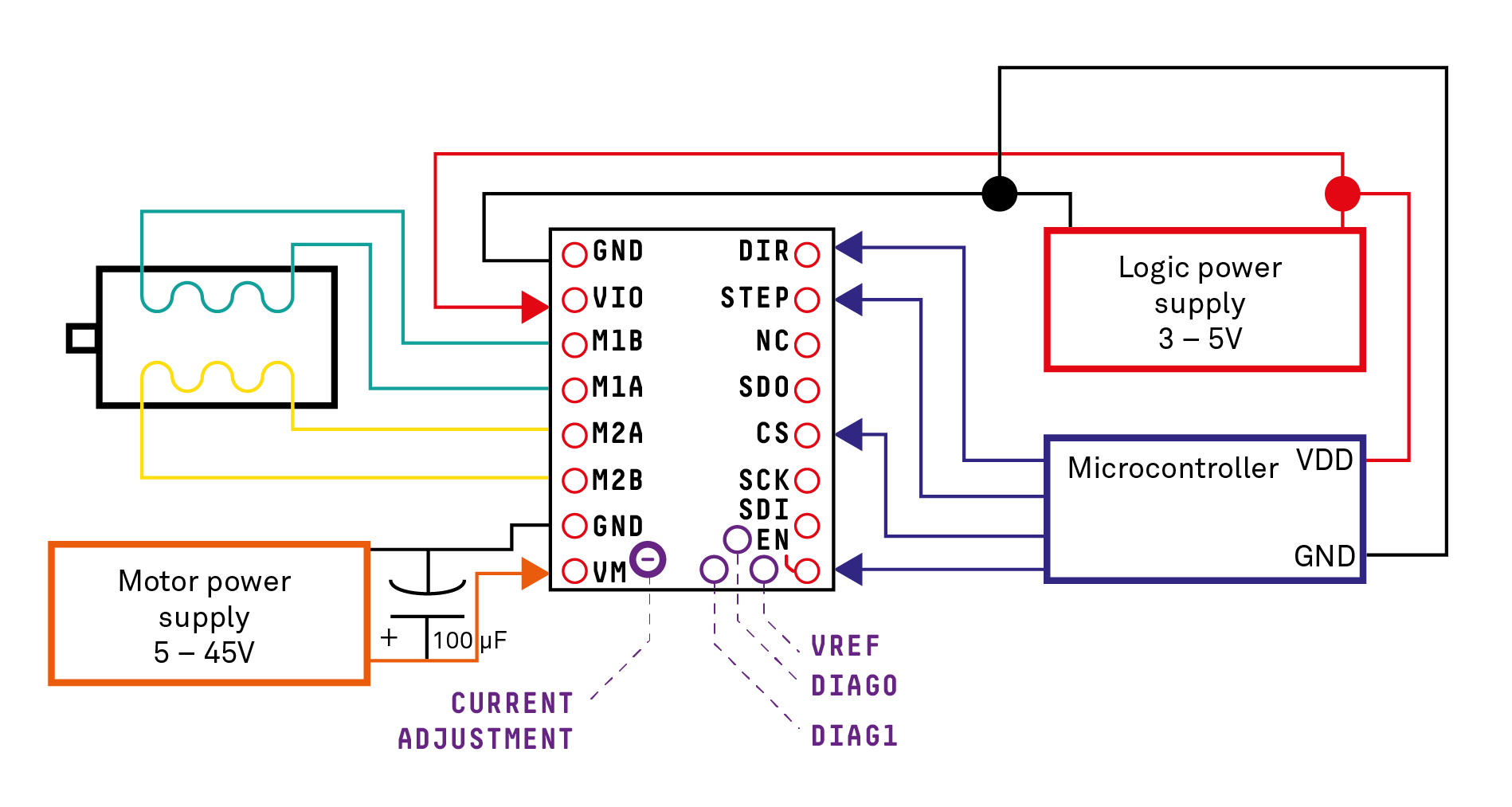
Stepper Driver Wiring Diagram. Stepper motor driver wiring diagram. Wiring diagram/schematic for a4988 stepper motor driver with arduino and stepper motor. This wiring diagram applies to all 80vdc 7a rated stepper drives including the g201, g201x, g202, g203v, g210, g210x, g212, g213v, gm215 and g214. Professional cnc kit for arduino, kuman grbl cnc shield + uno board + rampe.
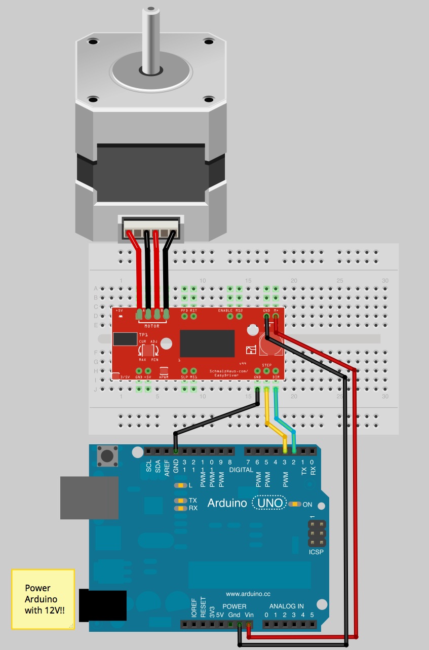 Redrex Stepper Wiring Diagram From schematron.org
Frequent power on/off switching will cause fast aging of the internal components, which will reduce the lifetime of stepper motor system. The collection that comprising chosen. I am wondering about a timing issue or wrong motor (200 steps/rev) or defective driver? This example can be used to let the motor spin continuously. I watched the you tube video on controlling big motors. There are just two things which are going to be present in any stepper motor wiring diagram.
Stepper motor driver circuit diagram schematic electrical4u
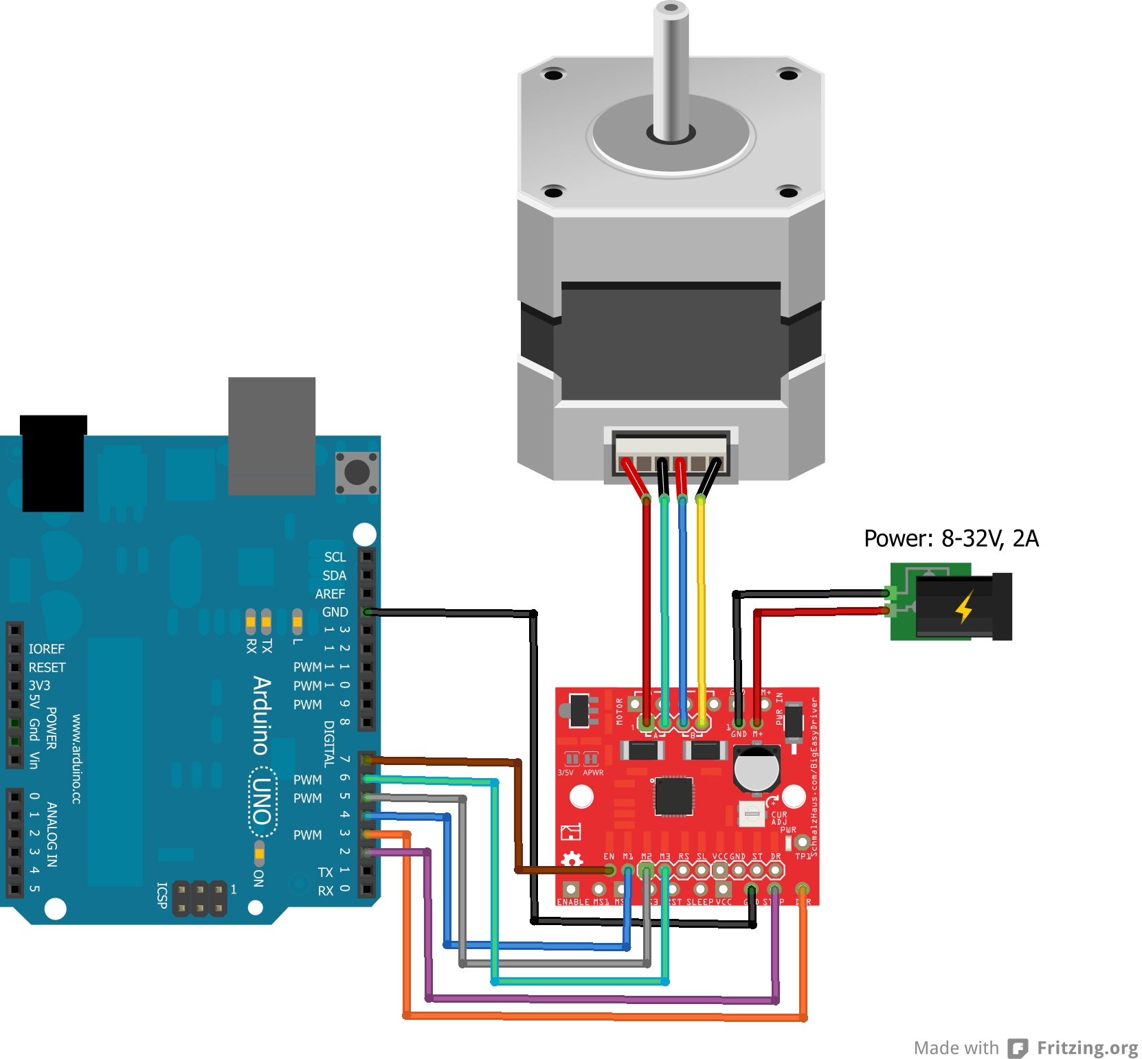
It is meant to assist all of the common person in developing a suitable program. November 24, 2021 by masuzi. Stepper motor driver wiring diagram. Consult the manual for your motor control for the most. It is not realistic to sort out all of the possible combinations of connections with an ohmmeter or by feel. The wiring diagram/schematic above shows you how to connect the a4899 driver to a stepper motor and the arduino.
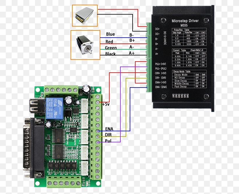 Source: favpng.com
Stepper motor driver wiring diagram. Nema 23 stepper motor datasheet specs applications. Tb6600 stepper motor driver with arduino tutorial. In this tutorial, you will learn how to control a stepper motor with the tb6600 microstepping driver and arduino. In the first example, i will show you how you can use this stepper motor driver without an arduino library.
 Source: the-diy-life.com
I have some electronics background but limited experience with stepper motors. In the first example, i will show you how. Follow the wiring diagram with each stepper motor November 24, 2021 by masuzi. Nema 23 stepper motor pinout features and example with arduino.
 Source: untpikapps.com
Arduino and stepper motor with pul\dir driver (dma). Only use the wiring diagram for the connections, and introduce in the. Bipolar stepper motor wiring diagram wiring diagram is a simplified gratifying pictorial representation of an electrical circuit it shows the components of the circuit as simplified shapes and the talent and signal associates amid the devices. Stepper motor driver circuit diagram tb6600 and arduino wiring stepper motor wiring diagram computer a4988 stepper motor driver with arduino. You can set the motor micro step via the first three dip switch.
 Source: wiring89.blogspot.com
I used a breadboard and some jumper wires to connect the driver board to an external. The collection that comprising chosen. The follow tablet shows the driver micro step. Driver wiring a complete stepper motor control system should contain stepper drives, dc power supply and controller (pulse source). Bipolar motors have 4 leads, while unipolar motors have 6 leads.
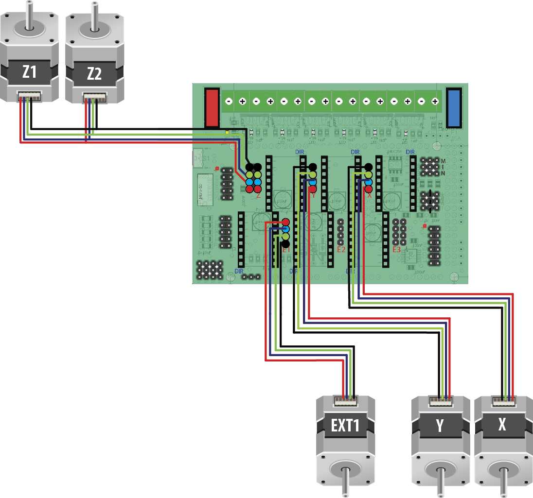 Source: faceitsalon.com
Strictly comply with the following rules: The first component is emblem that indicate electric component from the circuit. Nema 23 stepper motor wiring diagram. I used a breadboard and some jumper wires to connect the driver board to an external. The wiring diagram below shows you which connections you need to make.
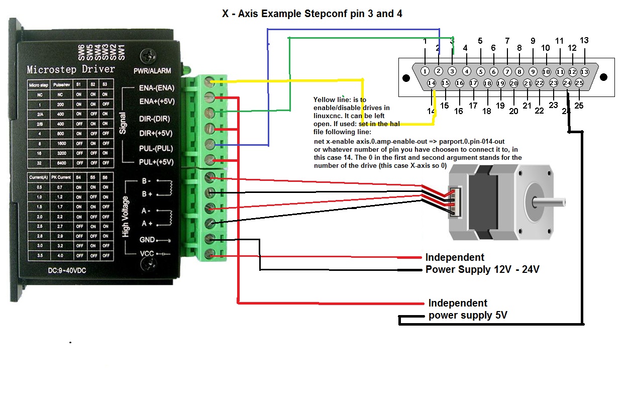 Source: 80.bloxhuette.de
In this tutorial, you will learn how to control a stepper motor with the tb6600 microstepping driver and arduino. Esp8266 12e pinout schematic circuit diagram well learn the correct pin identification by doing the following. In this instructable lets use a stepper motor as a rotary encoder to control another steppe. Step angle = motor step angle / micro step e.g. Easydriver v3 stepper motor driver rob 08368 sparkfun electronics.
 Source: lasergods.com
Nema 23 stepper motor pinout features nema 23 stepper motor datasheet specs nema 23 stepping motor 24 0 kg cm 4 nema 23 stepper motor bipolar 1 8. The follow tablet shows the driver micro step. This example can be used to let the motor spin continuously. This is a really easy method to identify a matching set of coils for a stepper motor when the vendor, or manufacturer doesn�t have it, or won�t provide it. Nema 23 stepper motor wiring diagram.
 Source: researchgate.net
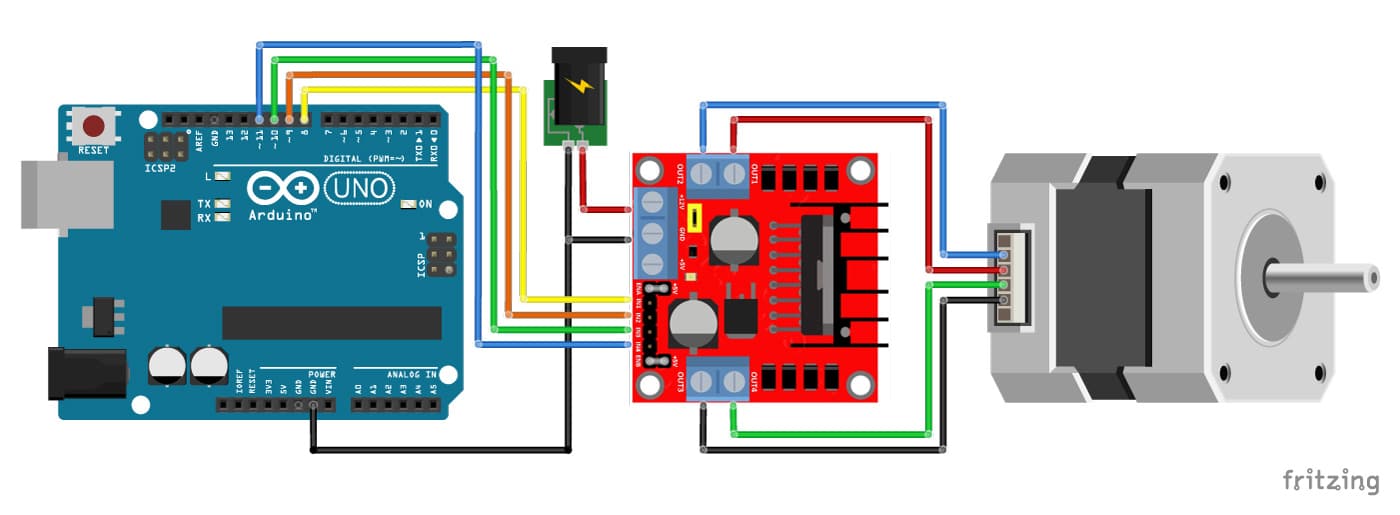
Bipolar motors have 4 leads, while unipolar motors have 6 leads. November 24, 2021 by masuzi. I used a breadboard and some jumper wires to connect the driver board to an external. In this tutorial, you will learn how to control a stepper motor with the tb6600 microstepping driver and arduino. L298n motor driver with stepper motor and arduino wiring diagram.
 Source: faceitsalon.com
Strictly comply with the following rules: The following is a typical system wiring diagram November 24, 2021 by masuzi. Looking at the diagram above, we can assume that the resistance between a1 and ac will be half of that between a1 and a2. I have included a wiring diagram and 3 example codes.
 Source: sinoning.com
Stepper motor wiring diagram wholesale, buy stepper motor wiring diagram from 67 stepper motor wiring diagram suppliers from china. 3 phase stepper motor wiring diagram it also will feature a picture of a kind that could be observed in the gallery of 3 phase stepper motor wiring diagram. I have included a wiring diagram and 3 example codes. Step angle = motor step angle / micro step e.g. Whats people lookup in this blog:
 Source: diagramweb.net
I have included a wiring diagram and 3 example codes. It is meant to assist all of the common person in developing a suitable program. Looking at the diagram above, we can assume that the resistance between a1 and ac will be half of that between a1 and a2. Tb6600 stepper motor driver with arduino tutorial. The 4 wires 5 wires and 6 wires stepper motors.
 Source: headcontrolsystem.com
Suggested electric fan wiring diagrams page 1 these diagrams show the use of. Please note that the g201x, g210x, g214, and gm215 have onboard dip switches for setting current, and no current set resistor is required. A complete stepper motor control system should contain stepper drives, dc power supply and controller (pulse source). Whats people lookup in this blog: The wiring diagram/schematic below shows you how to connect a stepper motor, power supply, and arduino to the l298n breakout board.
 Source: circuit-diagramz.com
The wiring diagram/schematic above shows you how to connect the a4899 driver to a stepper motor and the arduino. L298n motor driver with stepper motor and arduino wiring diagram. Suggested electric fan wiring diagrams page 1 these diagrams show the use of. This driver is easy to use and can control large stepper motors like a 3 a nema 23. Bipolar stepper motor wiring diagram wiring diagram is a simplified gratifying pictorial representation of an electrical circuit it shows the components of the circuit as simplified shapes and the talent and signal associates amid the devices.
 Source: schematron.org
Arduino and stepper motor with pul\dir driver (dma). The connections are also given in the following table: How to wire the circuit raspberry pi or arduino uno?. November 24, 2021 by masuzi. 3 phase stepper motor wiring diagram it also will feature a picture of a kind that could be observed in the gallery of 3 phase stepper motor wiring diagram.
 Source: 2020cadillac.com
The 4 wires 5 wires and 6 wires stepper motors. Professional cnc kit for arduino, kuman grbl cnc shield + uno board + rampe. I am wondering about a timing issue or wrong motor (200 steps/rev) or defective driver? The attached diagram shows dip settings and wiring. I have successfully used a uln2003 driver with a nema 11 motor and an uno.
 Source: wiringforums.com
A circuit is usually composed by several components. Stepper motor driver circuit diagram tb6600 and arduino wiring stepper motor wiring diagram computer a4988 stepper motor driver with arduino. A complete stepper motor control system should contain stepper drives, dc power supply and controller (pulse source). There are slight differences on how the different variant of stepper motors work ie. It reveals the parts of the circuit as simplified shapes and also the power and also signal links between the devices.
 Source: faceitsalon.com
The connections are also given in the table below. The follow tablet shows the driver micro step. This is a really easy method to identify a matching set of coils for a stepper motor when the vendor, or manufacturer doesn�t have it, or won�t provide it. The attached diagram shows dip settings and wiring. Bipolar motors have 4 leads, while unipolar motors have 6 leads.
 Source: annawiringdiagram.com
A stepper motor controller with driver circuit. I have included a wiring diagram and 3 example codes. Frequent power on/off switching will cause fast aging of the internal components, which will reduce the lifetime of stepper motor system. Follow the wiring diagram with each stepper motor Nema 23 stepper motor pinout features and example with arduino.
This site is an open community for users to do sharing their favorite wallpapers on the internet, all images or pictures in this website are for personal wallpaper use only, it is stricly prohibited to use this wallpaper for commercial purposes, if you are the author and find this image is shared without your permission, please kindly raise a DMCA report to Us.
If you find this site convienient, please support us by sharing this posts to your own social media accounts like Facebook, Instagram and so on or you can also save this blog page with the title stepper driver wiring diagram by using Ctrl + D for devices a laptop with a Windows operating system or Command + D for laptops with an Apple operating system. If you use a smartphone, you can also use the drawer menu of the browser you are using. Whether it’s a Windows, Mac, iOS or Android operating system, you will still be able to bookmark this website.
Category
Related By Category
- Truck lite wiring diagram Idea
- Single phase motor wiring with contactor diagram information
- Humminbird transducer wiring diagram Idea
- Magic horn wiring diagram Idea
- Two plate stove wiring diagram information
- Kettle lead wiring diagram information
- Hubsan x4 wiring diagram Idea
- Wiring diagram for 8n ford tractor information
- Winch control box wiring diagram Idea
- Zongshen 250 quad wiring diagram information