Static phase converter wiring diagram Idea
Home » Trend » Static phase converter wiring diagram Idea
Your Static phase converter wiring diagram images are available. Static phase converter wiring diagram are a topic that is being searched for and liked by netizens now. You can Get the Static phase converter wiring diagram files here. Get all free vectors.
If you’re searching for static phase converter wiring diagram images information linked to the static phase converter wiring diagram topic, you have come to the right site. Our site frequently provides you with suggestions for viewing the maximum quality video and image content, please kindly hunt and locate more informative video content and graphics that fit your interests.
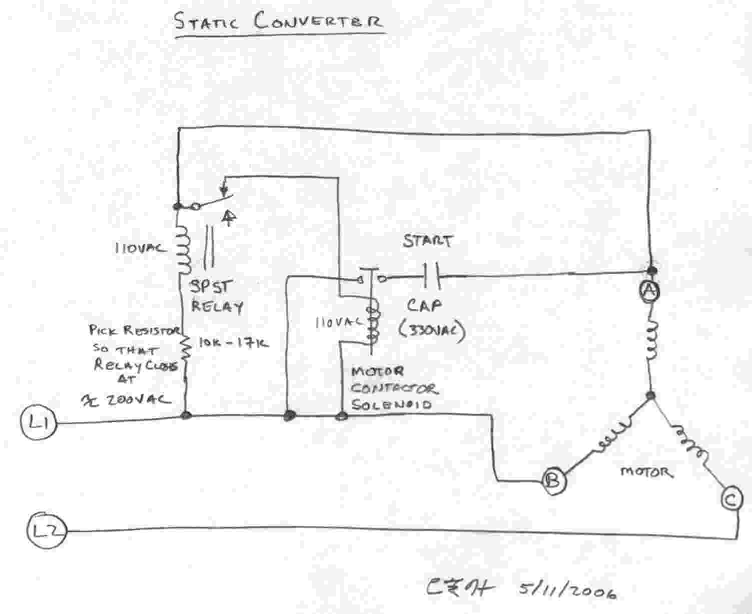
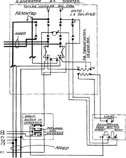
Static Phase Converter Wiring Diagram. Dorable static phase converter wiring diagram image collection. Consult the converter wiring diagram and nec before installation. Follow all local, city and national electric codes. $ in stock free shipping.
 3Phase Converters From users.rcn.com
Here is a picture gallery about 3 phase converter wiring diagram complete with the description of the image, please find the image you need. A static phase converter uses motor start capacitors to start a 3 phase motor on single phase power. Static phase converter used to start the load motor 1. If you look closely you will see all the basic elements from the very simple static phase converter diagram shown earlier. H a s static phase converter installation diagrams. Printable wiring diagram in pdf.
Static phase converter used to start the load motor 1.
3 phase motor static converter bolis com. It shows the elements of the circuit as simplified shapes, and the power and also signal connections between the tools. These capacitors are disconnected once the motor reaches full rpm. Motor horsepower must fall within the range of the static converter nemaplate rating. Installation manual with wiring diagrams here. Once running, the idler motor can then power the load motor.
 Source: practicalmachinist.com
A wiring diagram usually gives assistance not quite the relative viewpoint and. Single to 3 phase converter wiring diagram. Click here (external link) to check it out and here are some more wiring diagrams (that include run capacitors): A static phase converter uses motor start capacitors to start a 3 phase motor on single phase power. Wire the load motor in parallel
 Source: wiringdiagram.2bitboer.com
H a s static phase converter installation diagrams. Dorable static phase converter wiring diagram image collection. Static converters on phase a matic inc. The best marginal is always to use a verified and accurate phase a matic pam 300hd wiring diagram that’s provided from a trusted source. Once running, the idler motor can then power the load motor.
 Source: n0ksf.com
A wiring diagram usually gives assistance not quite the relative viewpoint and. Static phase converter is used 1. Equipment whose loads vary more than 50% can be.phase converters play role in wastewater systems for. Once running, the idler motor can then power the load motor. Also i see no ground wiring in the diagram, or neutrals.
 Source: dentistmitcham.com
The output terminals for your idler generator and loads are labeled t1, t2, and t3. Wire the load motor in parallel to the idler motor as per method 2 diagram no. Here is a basic wiring static phase converter diagram: Static phase converter is used 1. Wiring diagram and schematic role static 3 phase converter wiring diagram december 11, 2020 1 margaret byrd
Source: strawberry-sweet.blogspot.com
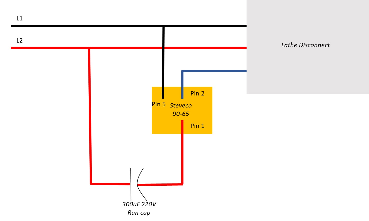
Follow all local, city and national electric codes. Static phase converter wiring diagram. Published by admin from january, 4 2014. ← static 3 phase converter wiring diagram 2006 honda civic tail light wiring diagram → There is an interesting document that includes a detailed explanation of how to add run capacitors to your static phase converter.
 Source: untpikapps.com
Do not connect220v power, or a ground or neutral wire from the utility, to the b terminal of the converter, as the resulting dead short would damage it instantly. It turning a bit faster than i can turn it by hand, i guess i�m calling wny supply again. ← static 3 phase converter wiring diagram 2006 honda civic tail light wiring diagram → A wiring diagram is a streamlined standard photographic depiction of an electric circuit. The best marginal is always to use a verified and accurate phase a matic pam 300hd wiring diagram that’s provided from a trusted source.
 Source: ricardolevinsmorales.com
$ in stock free shipping. H a s static phase converter installation diagrams. Static phase converter used to start the load motor 1. Collection of 3 phase rotary converter wiring diagram. Published by admin from january, 4 2014.

This type of converter is designed to be wired in on the single phase line side of the system, with this wiring configuration you not not need to modify your three phase wiring on your equipment. Table 2.2 in the installation manual shows the correct wire gauge size. Use the 3/8 inch allen wrench supplied with the phase converter. A wiring diagram usually gives assistance not quite the relative viewpoint and. This type of converter is designed to be wired in on the single phase line side of the system, with this wiring configuration you not not need to modify your three phase wiring on your equipment.
 Source: dentistmitcham.com
Phase a matic wiring diagram wiring diagram 10ee static converter was beware rotary phase converter that only runs when the pressor runs. Consult the converter wiring diagram and nec before installation. All wiring must be done by a licensed electrician. Static phase converter is used 1. Click here (external link) to check it out and here are some more wiring diagrams (that include run capacitors):
 Source: practicalmachinist.com
All wiring must be done by a licensed electrician. Pdf design of single phase to three static power converter. Click here (external link) to check it out and here are some more wiring diagrams (that include run capacitors): Once running, the idler motor can then power the load motor. The motor continues to run on the 2 single phase lines of power.
 Source: stickerdeals.net
A wiring diagram is a simplified traditional pictorial depiction of an electric circuit. These capacitors are disconnected once the motor reaches full rpm. Above is the field or power wiring diagram. Consult the converter wiring diagram and nec before installation. H a s static phase converter installation diagrams.
 Source: practicalmachinist.com
Here is a basic wiring static phase converter diagram: Follow all local, city and national electric codes. Also i see no ground wiring in the diagram, or neutrals. A wiring diagram usually gives assistance not quite the relative viewpoint and. Do not connect220v power, or a ground or neutral wire from the utility, to the b terminal of the converter, as the resulting dead short would damage it instantly.
 Source: users.rcn.com
Your input terminals are labeled l1 and l2. Wire the load motor in parallel $ in stock free shipping. The best marginal is always to use a verified and accurate phase a matic pam 300hd wiring diagram that’s provided from a trusted source. A static phase converter uses motor start capacitors to start a 3 phase motor on single phase power.
 Source: ricardolevinsmorales.com
Collection of 3 phase rotary converter wiring diagram. Wiring diagram and schematic role static 3 phase converter wiring diagram december 11, 2020 1 margaret byrd Wiring diagrams for their converters here. Once running, the idler motor can then power the load motor. Also i see no ground wiring in the diagram, or neutrals.
 Source: tianpinyt.blogspot.com
Use the 3/8 inch allen wrench supplied with the phase converter. A wiring diagram usually gives assistance not quite the relative viewpoint and. Single to 3 phase converter wiring diagram. Static converters on phase a matic inc. Static phase converter wiring diagrams.
 Source: ricardolevinsmorales.com
A static phase converter uses motor start capacitors to start a 3 phase motor on single phase power. The motor continues to run on the 2 single phase lines of power. The output terminals for your idler generator and loads are labeled t1, t2, and t3. 3 phase motor static converter bolis com. Wire the load motor in parallel
 Source: pressurediagram.mammarosa.eu
Collection of 3 phase rotary converter wiring diagram. Wire the load motor in parallel Dorable static phase converter wiring diagram image collection. The output terminals for your idler generator and loads are labeled t1, t2, and t3. Do not use t3 for any single phase loads.
 Source: tops-stars.com
All wiring must be done by a licensed electrician. Once running, the idler motor can then power the load motor. Follow all local, city and national electric codes. It shows the elements of the circuit as simplified shapes, and the power and also signal connections between the tools. Do not use t3 for any single phase loads.
This site is an open community for users to do submittion their favorite wallpapers on the internet, all images or pictures in this website are for personal wallpaper use only, it is stricly prohibited to use this wallpaper for commercial purposes, if you are the author and find this image is shared without your permission, please kindly raise a DMCA report to Us.
If you find this site value, please support us by sharing this posts to your preference social media accounts like Facebook, Instagram and so on or you can also save this blog page with the title static phase converter wiring diagram by using Ctrl + D for devices a laptop with a Windows operating system or Command + D for laptops with an Apple operating system. If you use a smartphone, you can also use the drawer menu of the browser you are using. Whether it’s a Windows, Mac, iOS or Android operating system, you will still be able to bookmark this website.
Category
Related By Category
- Predator 670 engine wiring diagram Idea
- Frsky x8r wiring diagram information
- Pioneer ts wx130da wiring diagram Idea
- Johnson 50 hp wiring diagram Idea
- Kohler voltage regulator wiring diagram Idea
- Johnson 50 hp outboard wiring diagram information
- Kti hydraulic remote wiring diagram Idea
- Pyle plpw12d wiring diagram information
- Tx9600ts wiring diagram information
- Lifan 50cc wiring diagram information