Start stop wiring diagram one switch Idea
Home » Trending » Start stop wiring diagram one switch Idea
Your Start stop wiring diagram one switch images are available in this site. Start stop wiring diagram one switch are a topic that is being searched for and liked by netizens today. You can Get the Start stop wiring diagram one switch files here. Find and Download all free images.
If you’re searching for start stop wiring diagram one switch images information linked to the start stop wiring diagram one switch topic, you have pay a visit to the right site. Our site always provides you with hints for viewing the maximum quality video and image content, please kindly hunt and locate more informative video articles and images that fit your interests.
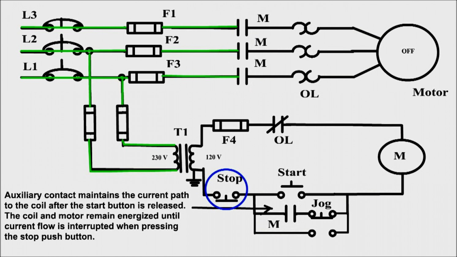
Start Stop Wiring Diagram One Switch. Pilot light l2 4 2 3 pilot light start stop bulletin 1495 normally closed auxiliary contacts are required. The first component is emblem that indicate electric component from the circuit. Wire your trainer so that pressing push button 1 energizes the contactor and it stays latched in until you press push button 2. Some rooms remain dark and dreary with a single ceiling or wall light fixture.
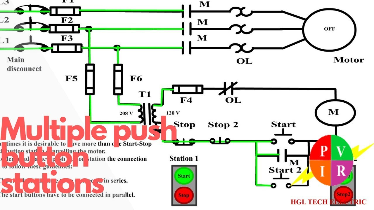 Start Stop Switch Wiring Diagram Cadician�s Blog From 2020cadillac.com
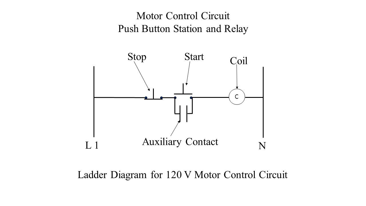
Stop blue 5 red 1 yellow 2 black 3 connect to terminal a1 of the left hand coil and to terminal number 95 of the overload relay forward coil and A variation on the control circuit in figure 1 is the provision of only one start position with multiple stop positions. They show the relative location of the components. They can be used as a guide when wiring the controller. Emergency stop nvr switch wiring diagram wiring diagram line wiring diagram. 1 remote stop 1 l1, x1 or 1 figure e start/stop with pilot light black 3/14 yellow 2/13 red 1 start stop figure g pilot light (motor stop) 260810 d1 forward add connector “f” between aux.
When you press the start button and the stop button.
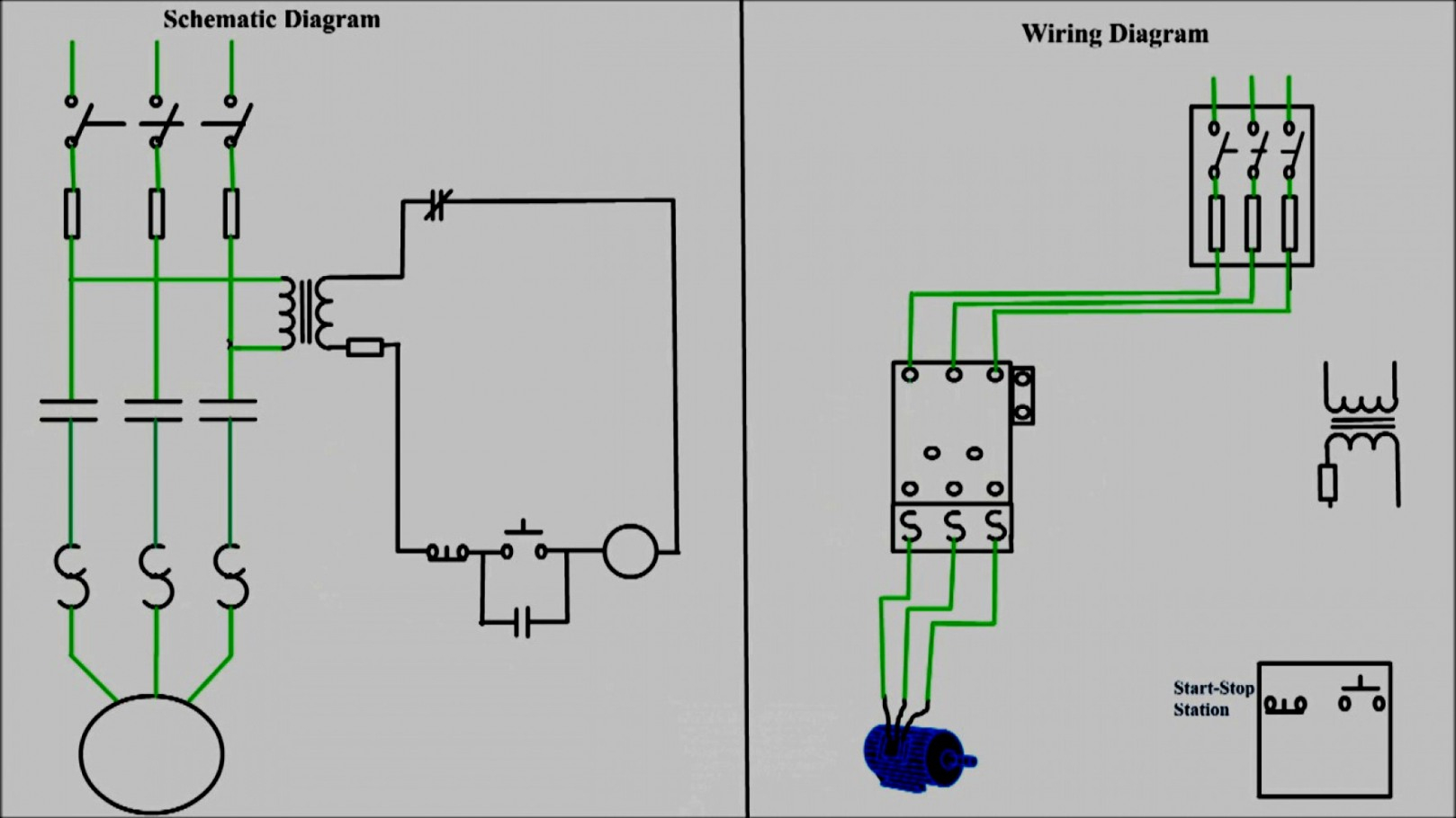
Compre 250 voltage universal ck21d safety s afe cut off and barato frete grátis avaliações reais fotos joom motor start push lathe mill drill at affordable free shipping real reviews photos save fingers lives a no release for the hackaday. A variation on the control circuit in figure 1 is the provision of only one start position with multiple stop positions. A circuit is generally composed by many components. Contact terminals 2 and 4 reverse. Wiring diagrams show the connections to the controller. Mitosis worksheet & diagram identification.
 Source: mainetreasurechest.com
Mitosis worksheet & diagram identification. Start stop push button wiring diagram emergency. Wiring a push button stop start switch. Start stop push button station wiring diagram unique triumph. A variation on the control circuit in figure 1 is the provision of only one start position with multiple stop positions.
 Source: youtube.com
Gerebek tokopedia mircom lt 691 cnsis 204 specifications sheet specification new front amp data whs whd wht waterproof switches dimension thailand transformator isolasi hexta pabrik ilizer trafo co id redarc smart kit 12 volt 100 charger 331. Wiring diagram book a1 15 b1 b2 16 18 b3 a2 b1 b3 15 supply voltage 16 18 l m h 2 levels b2 l1 f u 1 460 v f u 2 l2 l3 gnd h1 h3 h2 h4 f u 3 x1a f u 4 f u 5 x2a r power on optional x1 x2115 v 230 v h1 h3 h2 h4 optional connection electrostatically shielded transformer f u 6 off on m l1 l2 1 2 stop ol m start 3 start start fiber optic. Mitosis worksheet & diagram identification. Start stop push button wiring diagram emergency. Figure 1 two start and stop control positions in a circuit.
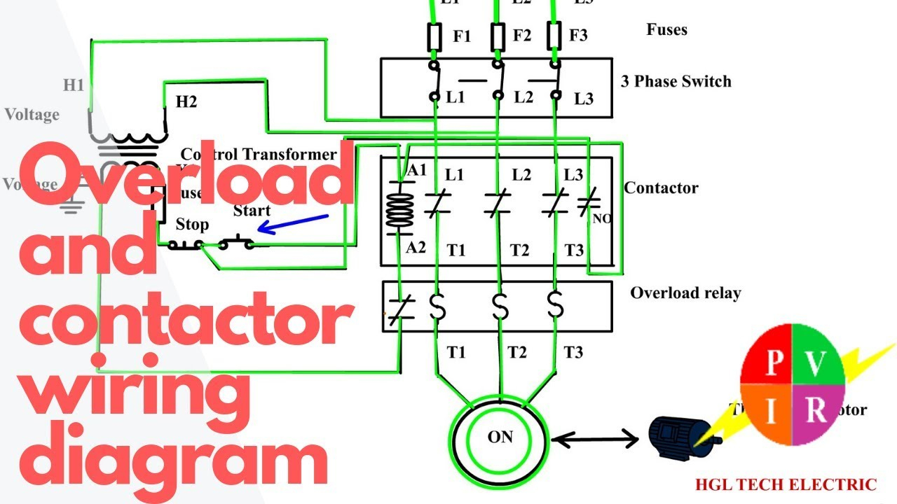 Source: 2020cadillac.com
The first component is emblem that indicate electric component from the circuit. Learn how to wire a time switch and connect the wires to the appropriate terminals. Emergency stop button wiring diagram download. Start stop push button station wiring diagram unique triumph. Stop blue 5 red 1 yellow 2 black 3 connect to terminal a1 of the left hand coil and to terminal number 95 of the overload relay forward coil and
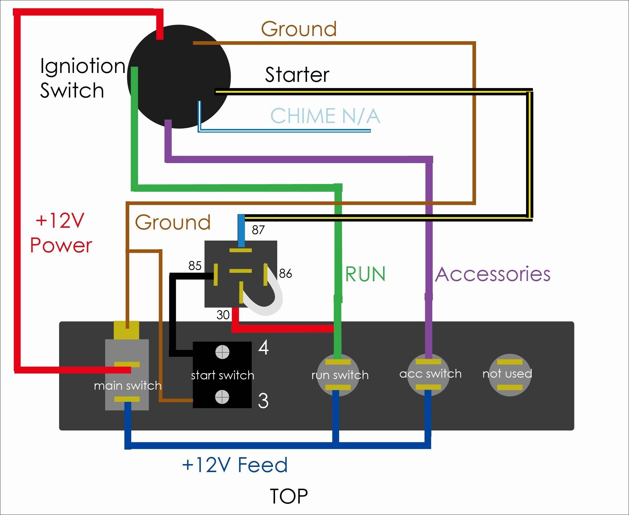 Source: apkpure.com
I am here with giving you a vfd start stop wiring diagram for running a vfd through panel board push button and keypad of the vfd (it is called hmi). Otherwise, the arrangement will not function. If not, the arrangement won’t work as it ought to be. Wiring diagram book a1 15 b1 b2 16 18 b3 a2 b1 b3 15 supply voltage 16 18 l m h 2 levels b2 l1 f u 1 460 v f u 2 l2 l3 gnd h1 h3 h2 h4 f u 3 x1a f u 4 f u 5 x2a r power on optional x1 x2115 v 230 v h1 h3 h2 h4 optional connection electrostatically shielded transformer f u 6 off on m l1 l2 1 2 stop ol m start 3 start start fiber optic. Learn how to wire a time switch and connect the wires to the appropriate terminals.
 Source: 2020cadillac.com
Then wire one of the contacts in on the contactor to turn on light 1 whenever the contactor energizes. Posted on may 14, 2018 august 9, 2018 by headcontrolsystem. Otherwise, the arrangement will not function. Some rooms remain dark and dreary with a single ceiling or wall light fixture. Then wire one of the contacts in on the contactor to turn on light 1 whenever the contactor energizes.
 Source: tonetastic.info
Wire your trainer so that pressing push button 1 energizes the contactor and it stays latched in until you press push button 2. Vfd start stop wiring diagram: Single station with the starter. Vfd is a short form of variable frequency drive or variable voltage variable frequency drive.the vfds are working based on changing the input frequency and input voltage of the motor, we can change. These instructions will likely be easy to.
 Source: wholefoodsonabudget.com
Emergency stop nvr switch wiring diagram wiring diagram line wiring diagram. Wiring a single phase motor through 3 contactor how and why start stop push on diagram for android is it allowed to energize coil from the voltage source coming same. The other thing that you will find a circuit diagram would be lines. A toggle switch is so named because it is a switch with a long handle, or toggle, to control it. Single station with the starter.
 Source: wholefoodsonabudget.com
How to wire start stop station to control three phase motor. A toggle switch is so named because it is a switch with a long handle, or toggle, to control it. Vfd start stop wiring diagram: See image below for an example of 3 wire control being used to pull in a contactor to start a 3 phase motor. 1 remote stop 1 l1, x1 or 1 figure e start/stop with pilot light black 3/14 yellow 2/13 red 1 start stop figure g pilot light (motor stop) 260810 d1 forward add connector “f” between aux.
Source: fjelloghjem.blogspot.com
Contact terminals 2 and 4 reverse. Emergency stop button wiring diagram download. Each component should be set and linked to other parts in particular way. Otherwise the structure won t function as it ought to be. Emolatur is offline push button for stop.
 Source: annawiringdiagram.com
1 remote stop 1 l1, x1 or 1 figure e start/stop with pilot light black 3/14 yellow 2/13 red 1 start stop figure g pilot light (motor stop) 260810 d1 forward add connector “f” between aux. When you press the start button and the stop button. It includes guidelines and diagrams for various types of wiring techniques along with other products like lights, windows, and so forth. Wiring a push button stop start switch. Posted on may 14, 2018 august 9, 2018 by headcontrolsystem.
 Source: pinterest.com
Otherwise, the structure won’t function as it ought to be. A variation on the control circuit in figure 1 is the provision of only one start position with multiple stop positions. One of the jog circuit designs is the two circuit pushbutton. Compre 250 voltage universal ck21d safety s afe cut off and barato frete grátis avaliações reais fotos joom motor start push lathe mill drill at affordable free shipping real reviews photos save fingers lives a no release for the hackaday. Collection of start stop wiring diagram.
 Source: model-engineer.co.uk
Collection of start stop wiring diagram. There are just two things which are going to be found in any push button starter switch wiring diagram. Otherwise the structure won t function as it ought to be. Wiring diagram book a1 15 b1 b2 16 18 b3 a2 b1 b3 15 supply voltage 16 18 l m h 2 levels b2 l1 f u 1 460 v f u 2 l2 l3 gnd h1 h3 h2 h4 f u 3 x1a f u 4 f u 5 x2a r power on optional x1 x2115 v 230 v h1 h3 h2 h4 optional connection electrostatically shielded transformer f u 6 off on m l1 l2 1 2 stop ol m start 3 start start fiber optic. Emergency stop nvr switch wiring diagram wiring diagram line wiring diagram.
 Source: 2020cadillac.com
Contact terminals 2 and 4 reverse. Learn how to wire a time switch and connect the wires to the appropriate terminals. These instructions will likely be easy to. Single station with the starter. Gerebek tokopedia mircom lt 691 cnsis 204 specifications sheet specification new front amp data whs whd wht waterproof switches dimension thailand transformator isolasi hexta pabrik ilizer trafo co id redarc smart kit 12 volt 100 charger 331.
 Source: annawiringdiagram.com
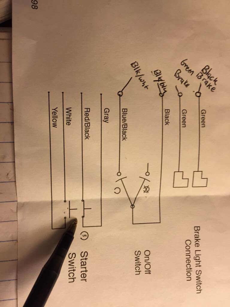
Everything rides on circuit thats being constructed. Otherwise, the structure won’t function as it ought to be. A circuit is generally composed by many components. Start stop switch wiring diagram source. Otherwise, the arrangement will not function.
 Source: electricala2z.com
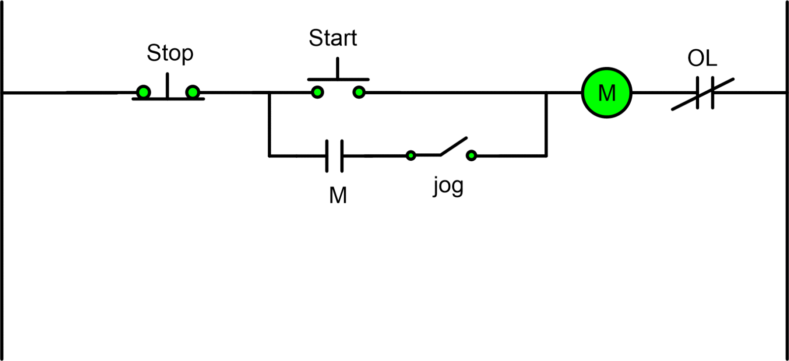
Three wire start stop diagram start stop wiring diagram one switch inside 3 wire stop start wiring diagram by admin through the thousand pictures on the net in relation to 3 wire stop start wiring diagram, we selects the very best libraries having greatest resolution exclusively for you, and now this images is one of images selections in your greatest photographs gallery. Vfd start stop wiring diagram: The advantages of 3 phase contactor wiring diagram start stop. See image below for an example of 3 wire control being used to pull in a contactor to start a 3 phase motor. Wiring diagram single motor with start stop switch electrostudy intended for 3 electrical circuit diagram electrical wiring diagram home electrical wiring start stop.
 Source: faceitsalon.com
Otherwise the structure won t function as it ought to be. The other thing that you will find a circuit diagram would be lines. Each component should be set and linked to… The first component is emblem that indicate electric component from the circuit. A circuit is generally composed by many components.
 Source: annawiringdiagram.com
If not, the arrangement won’t work as it ought to be. Wiring diagrams show the connections to the controller. Emolatur is offline push button for stop. The other thing that you will find a circuit diagram would be lines. Wiring diagram book a1 15 b1 b2 16 18 b3 a2 b1 b3 15 supply voltage 16 18 l m h 2 levels b2 l1 f u 1 460 v f u 2 l2 l3 gnd h1 h3 h2 h4 f u 3 x1a f u 4 f u 5 x2a r power on optional x1 x2115 v 230 v h1 h3 h2 h4 optional connection electrostatically shielded transformer f u 6 off on m l1 l2 1 2 stop ol m start 3 start start fiber optic.
 Source: wiringforums.com
Start stop switch wiring diagram source. I am here with giving you a vfd start stop wiring diagram for running a vfd through panel board push button and keypad of the vfd (it is called hmi). These instructions will likely be easy to. Each component should be set and linked to… Each component should be placed and connected with different parts in particular manner.
This site is an open community for users to do sharing their favorite wallpapers on the internet, all images or pictures in this website are for personal wallpaper use only, it is stricly prohibited to use this wallpaper for commercial purposes, if you are the author and find this image is shared without your permission, please kindly raise a DMCA report to Us.
If you find this site convienient, please support us by sharing this posts to your own social media accounts like Facebook, Instagram and so on or you can also save this blog page with the title start stop wiring diagram one switch by using Ctrl + D for devices a laptop with a Windows operating system or Command + D for laptops with an Apple operating system. If you use a smartphone, you can also use the drawer menu of the browser you are using. Whether it’s a Windows, Mac, iOS or Android operating system, you will still be able to bookmark this website.
Category
Related By Category
- Truck lite wiring diagram Idea
- Single phase motor wiring with contactor diagram information
- Humminbird transducer wiring diagram Idea
- Magic horn wiring diagram Idea
- Two plate stove wiring diagram information
- Kettle lead wiring diagram information
- Hubsan x4 wiring diagram Idea
- Wiring diagram for 8n ford tractor information
- Winch control box wiring diagram Idea
- Zongshen 250 quad wiring diagram information