Start stop wiring diagram Idea
Home » Trend » Start stop wiring diagram Idea
Your Start stop wiring diagram images are ready. Start stop wiring diagram are a topic that is being searched for and liked by netizens now. You can Find and Download the Start stop wiring diagram files here. Download all free vectors.
If you’re searching for start stop wiring diagram images information related to the start stop wiring diagram interest, you have visit the ideal site. Our website frequently provides you with hints for viewing the maximum quality video and image content, please kindly hunt and find more enlightening video articles and graphics that match your interests.
Start Stop Wiring Diagram. Figure 1 three wire control giving low voltage protection. Start date feb 11, 2012; I am here with giving you a vfd start stop wiring diagram for running a vfd through panel board push button and keypad of the vfd (it is called hmi). How to wire a start stop station controlling 120 volt magnetic starter quora.
 Contactor Wiring Diagram Start Stop For Your Needs From mamvic.com
The most common use of 3 wire control is a start/stop control. When you press the start button and the stop button is not pressed, the 24vdc relay energizes and it pulls in the r1 contactor that feeds three phase power to the motor. I am here with giving you a vfd start stop wiring diagram for running a vfd through panel board push button and keypad of the vfd (it is called hmi). We have collected lots of images, ideally this photo serves for you, and also aid you in finding the response you are searching for. Start stop switch wiring diagram from content.instructables.com print the wiring diagram off plus use highlighters to trace the signal. Wiring diagram single motor with start stop switch basic control motor to get start or stop the motor use a push button switch as a trigger a motor.
Automatic transferred switch (ats) circuit diagram.
Wiring diagrams do not show the operating mechanism since it is not electrically controlled. 5 3 phase contactor wiring diagram start stop relay cable When you press the start button and the stop button is not pressed, the 24vdc relay energizes and it pulls in the r1 contactor that feeds three phase power to the motor. Tags button circuit contact diagram start wiring wiring diagram discuss wiring diagram for start/stop ? Automatic transferred switch (ats) circuit diagram. Start stop jog circuit motor control diagram electrical a2z.
 Source: electricala2z.com
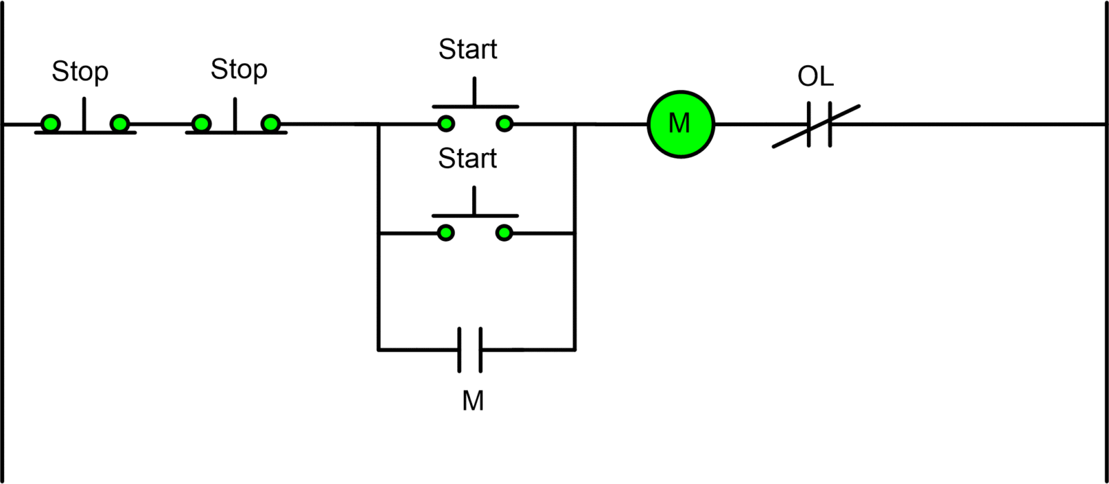
Vfd start stop wiring diagram: The most common use of 3 wire control is a start/stop control. Pressing the jog button creates a current path directly to the load bypassing the seal in of the control circuit. This can arise when a number of emergency stop positions might be required in a plant. Injunction of two wires is generally indicated by black dot to the junction of two lines.
 Source: mainetreasurechest.com
Occasionally, the wires will cross. Motor control can be done with a plc program. Wiring diagram for motor starter 3 phase controller failure relay electrical pleasing three electrical wiring electrical circuit diagram home electrical wiring. The circuit will operate as a normal three wire circuit if the start stop pushbuttons are used. Considering grating to remove, replace or repair the wiring in an automobile, having an accurate and detailed start.
 Source: 2020cadillac.com
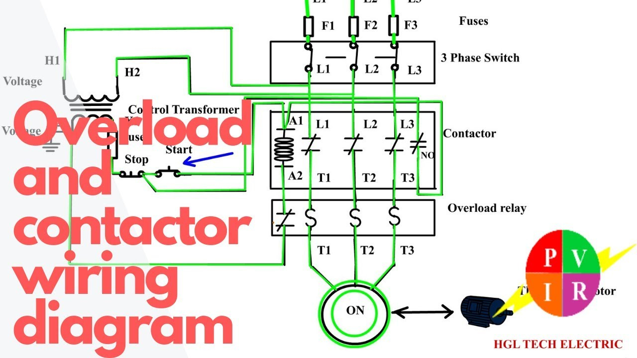
This video is a step by step explanation of wiring start stop basics. Wiring diagram for start/stop ? See image below for an example of 3 wire control being used to pull in a contactor to start a 3 phase motor. Start stop switch wiring diagram from content.instructables.com print the wiring diagram off plus use highlighters to trace the signal. Home decorating style 2020 for 3 phase start stop wiring diagram, you can see 3 phase start stop wiring diagram and more pictures for home interior designing 2020 180206 at manuals library.
![[DIAGRAM] 3 Wire Start Stop Diagram FULL Version HD [DIAGRAM] 3 Wire Start Stop Diagram FULL Version HD](https://ricardolevinsmorales.com/wp-content/uploads/2018/09/start-stop-wiring-diagram-symbols-marvellous-motor-control-circuit-diagram-start-stop-wire-at-10g.jpg) Source: pvdiagramshannono.carnevalecampagnolo.it
Source: pvdiagramshannono.carnevalecampagnolo.it
This can arise when a number of emergency stop positions might be required in a plant. Injunction of two wires is generally indicated by black dot to the junction of two lines. Start stop jog circuit motor control diagram electrical a2z. Vfd is a short form of variable frequency drive or variable voltage variable frequency drive.the vfds are working based on changing the input frequency and input voltage of the motor, we can change. 1 trick that we 2 to printing a similar wiring plan off twice.
 Source: electricala2z.com
The circuit will operate as a normal three wire circuit if the start stop pushbuttons are used. Vfd is a short form of variable frequency drive or variable voltage variable frequency drive.the vfds are working based on changing the input frequency and input voltage of the motor, we can change. Home decorating style 2020 for 3 phase start stop wiring diagram, you can see 3 phase start stop wiring diagram and more pictures for home interior designing 2020 180206 at manuals library. Wiring diagram comes with a number of easy to stick to wiring diagram guidelines. As stated previous, the traces at a start stop switch wiring diagram signifies wires.
 Source: annawiringdiagram.com
Automatic transferred switch (ats) circuit diagram. How to wire a start stop station controlling 120 volt magnetic starter quora. Pressing the jog button creates a current path directly to the load bypassing the seal in of the control circuit. Wiring diagram comes with a number of easy to stick to wiring diagram guidelines. A three wire start stop circuit with multiple push ons.

1 trick that we 2 to printing a similar wiring plan off twice. A three wire start stop circuit with multiple push ons. The circuit will operate as a normal three wire circuit if the start stop pushbuttons are used. They show the relative location of the components. They are used in applications which do not require undervoltage protection.
 Source: wiring89.blogspot.com
Automatic transferred switch (ats) circuit diagram. A wiring diagram is a streamlined conventional photographic representation of an electric circuit. Figure 1 two start and stop control positions in a circuit. The most common use of 3 wire control is a start/stop control. As long as you follow the ladder diagram and take it one wire at a time its simple.this.
 Source: wholefoodsonabudget.com
Three phase contactor wiring diagram electrical info pics. 3 phase contactor wiring diagram in 3 phase start stop wiring diagram diagram fuse box how to find out Wiring diagram also gives beneficial recommendations for projects which may need some extra tools. Push to make ptm switch use to start the motor and push. Start stop switch wiring diagram from content.instructables.com print the wiring diagram off plus use highlighters to trace the signal.
 Source: apkpure.com
Control wiring 3 wire start stop circuit tw controls. Start stop wiring diagram one switch. Occasionally, the wires will cross. Wiring diagram book a1 15 b1 b2 16 18 b3 a2 b1 b3 15 supply voltage 16 18 l m h 2 levels b2 l1 f u 1 460 v f u 2. They show the relative location of the components.
 Source: kovodym.blogspot.com
3 phase contactor wiring diagram in 3 phase start stop wiring diagram diagram fuse box how to find out Injunction of two wires is generally indicated by black dot to the junction of two lines. Wiring diagram comes with a number of easy to stick to wiring diagram guidelines. This video is a step by step explanation of wiring start stop basics. However, it doesn’t mean link between the wires.
 Source: tonetastic.info
We have collected lots of images, ideally this photo serves for you, and also aid you in finding the response you are searching for. 3 wire start stop wiring diagram elec eng world diagram wire circuit. Start stop switch wiring diagram source. At times, the wires will cross. According to earlier, the lines at a start stop push button wiring diagram signifies wires.
 Source: 2020cadillac.com
3 wire start stop wiring diagram elec eng world diagram wire circuit. We have collected lots of images, ideally this photo serves for you, and also aid you in finding the response you are searching for. Wiring diagram single motor with start stop switch basic control motor to get start or stop the motor use a push button switch as a trigger a motor. They can be used as a guide when wiring the controller. Motor control can be done with a plc program.
 Source: youtube.com
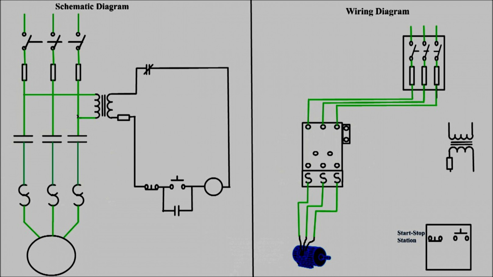
The wiring diagram for connecting thee phase motor to the supply along with control wiring is shown in figure below. See image below for an example of 3 wire control being used to pull in a contactor to start a 3 phase motor. Automatic transferred switch (ats) circuit diagram. This video is a step by step explanation of wiring start stop basics. Here is a picture gallery about motor starter wiring diagram start stop complete with the description of the image please find the image you need.
 Source: wiringdiagramharnessideas.blogspot.com
Typical wiring diagrams for push button control stations 7 start stop control wiring diagrams single station with motor stopped pilot light l1 start l2 i 1 stop 2 oi 3 n wol. 1 trick that we 2 to printing a similar wiring plan off twice. Pressing the jog button creates a current path directly to the load bypassing the seal in of the control circuit. Start stop switch wiring diagram source. When you make use of your finger or perhaps the actual circuit with your eyes, it is easy to mistrace the circuit.
 Source: mamvic.com
As long as you follow the ladder diagram and take it one wire at a time its simple.this. 1 trick that we 2 to printing a similar wiring plan off twice. Automatic transferred switch (ats) circuit diagram. This video is a step by step explanation of wiring start stop basics. Wiring diagram single motor with start stop switch basic control motor to get start or stop the motor use a push button switch as a trigger a motor.
 Source: wholefoodsonabudget.com
Typical wiring diagrams for push button control stations 7 start stop control wiring diagrams single station with motor stopped pilot light l1 start l2 i 1 stop 2 oi 3 n w o l. 1 trick that we 2 to printing a similar wiring plan off twice. However, it doesn’t mean link between the wires. Wiring diagram for start/stop ? Start stop switch wiring diagram from content.instructables.com print the wiring diagram off plus use highlighters to trace the signal.
 Source: ikantujuh.blogspot.com
This can arise when a number of emergency stop positions might be required in a plant. The most common use of 3 wire control is a start/stop control. However it doesn t mean link between the wires. Injunction of two wires is generally indicated by black dot to the junction of two lines. Pressing the jog button creates a current path directly to the load bypassing the seal in of the control circuit.
This site is an open community for users to do sharing their favorite wallpapers on the internet, all images or pictures in this website are for personal wallpaper use only, it is stricly prohibited to use this wallpaper for commercial purposes, if you are the author and find this image is shared without your permission, please kindly raise a DMCA report to Us.
If you find this site serviceableness, please support us by sharing this posts to your own social media accounts like Facebook, Instagram and so on or you can also bookmark this blog page with the title start stop wiring diagram by using Ctrl + D for devices a laptop with a Windows operating system or Command + D for laptops with an Apple operating system. If you use a smartphone, you can also use the drawer menu of the browser you are using. Whether it’s a Windows, Mac, iOS or Android operating system, you will still be able to bookmark this website.
Category
Related By Category
- Predator 670 engine wiring diagram Idea
- Frsky x8r wiring diagram information
- Pioneer ts wx130da wiring diagram Idea
- Johnson 50 hp wiring diagram Idea
- Kohler voltage regulator wiring diagram Idea
- Johnson 50 hp outboard wiring diagram information
- Kti hydraulic remote wiring diagram Idea
- Pyle plpw12d wiring diagram information
- Tx9600ts wiring diagram information
- Lifan 50cc wiring diagram information