Standing pilot gas valve wiring diagram information
Home » Trending » Standing pilot gas valve wiring diagram information
Your Standing pilot gas valve wiring diagram images are available in this site. Standing pilot gas valve wiring diagram are a topic that is being searched for and liked by netizens now. You can Download the Standing pilot gas valve wiring diagram files here. Get all free vectors.
If you’re looking for standing pilot gas valve wiring diagram pictures information linked to the standing pilot gas valve wiring diagram interest, you have come to the right site. Our website frequently gives you suggestions for viewing the highest quality video and picture content, please kindly surf and locate more enlightening video content and images that match your interests.
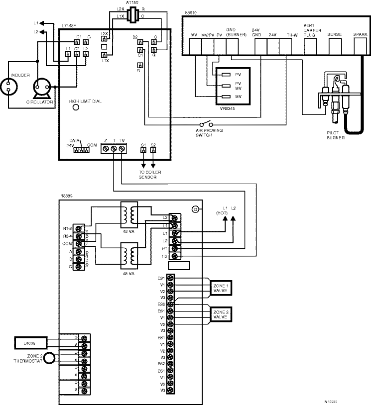
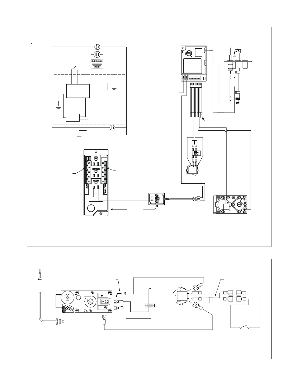
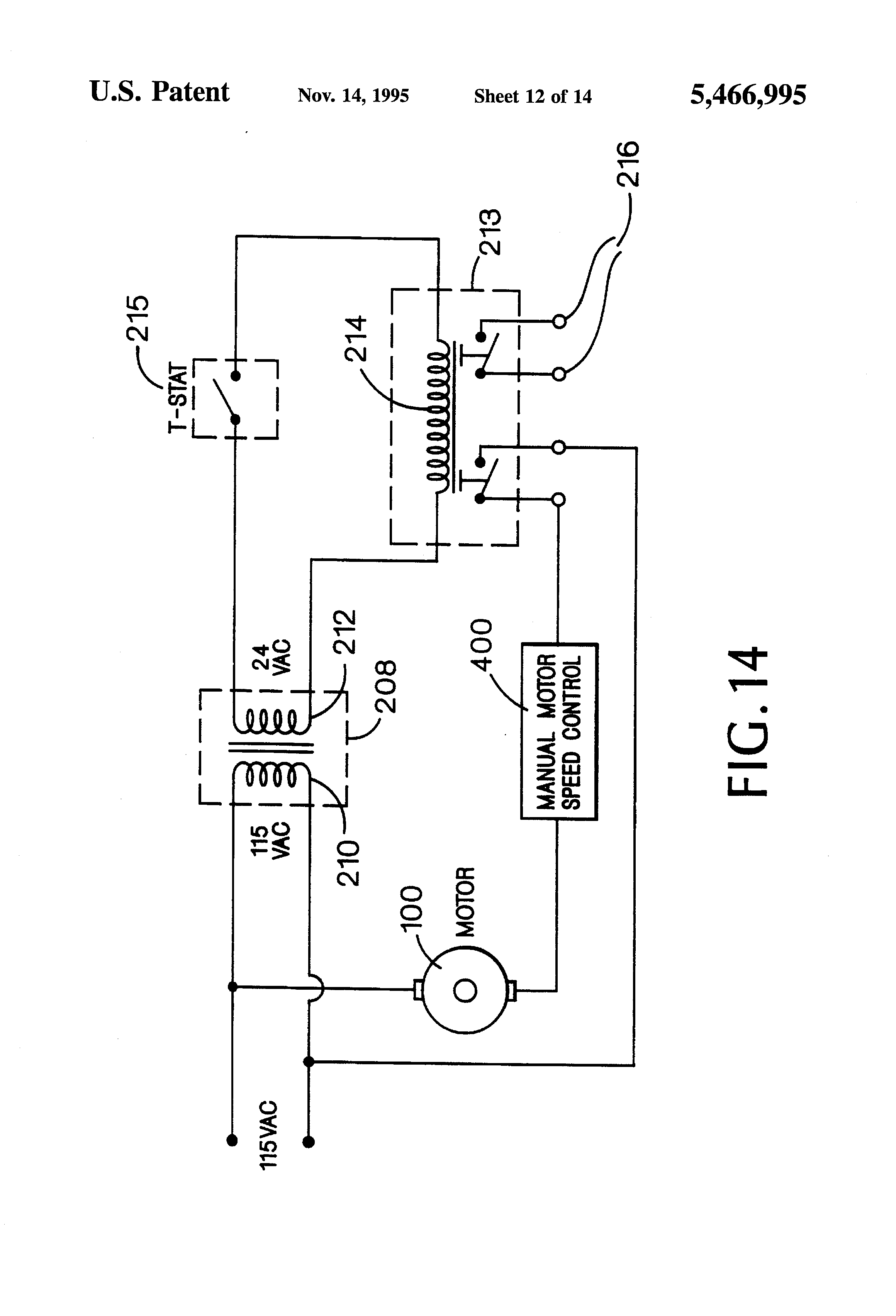
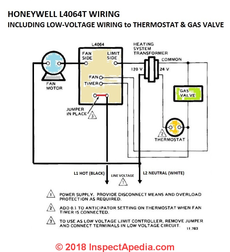
Standing Pilot Gas Valve Wiring Diagram. Voltage drop across the switch terminals burner on: Field controls gas vent dampers gvd are made of stainless steel and is available in 8 sizes 4 through 10 and 12. Lennox thermostat wiring diagram nordyne furnace wiring diagram lennox wiring schematics furnace gas valve wiring diagram lennox furnace. Cummins marine fuel shutoff solenoid wiring 101.
Millivolt Gas Valve Wiring Diagram Wiring Diagram Database From wiringdiagram99.blogspot.com
The thermopile, energized by the pilot flame, generates sufficient power to operate the gas valve and on/off switch. Standing pilot with induced draft furnaces, wiring diagram a/c ready , m1g(b,c,d) 077, 090 models. Not using this makes no. Insert clean, deburred tubing all the way through the fitting. Damper must be fully open before main burners light. Limit transformer pressure switch combustion fan l1 n r c 24 v 115 v black black black black orange orange green white
Gas valve cross reference 9 standing pilot gas flow to the pilot burner is controlled by a safety valve which is manually operated and held in by current generated from a thermocouple placed in the pilot flame.
Gas solenoid valve wiring diagram lovely fine white rodgers gas. Proven pilot the thermostat calls for heat and simultaneously energizes the The manifold regulation look at the rating plate on the furnace note: You want a heater that�s designed t. Gas valve actuator types manual standing pilot valve manually turned on and off for each heating cycle. Disconnect the pilot gas tube from the valve 4.
 Source: wiring89.blogspot.com
The white rogers zone valves have three wires, white red and green. Damper must be fully open before main burners light. A water heater or furnace thermocouple is a heat sensitive probe that sends an electric signal to the gas valve whenever the pilot is lit. The thermopile, energized by the pilot flame, generates sufficient power to operate the gas valve and on/off switch. Ahe altitude conversion manual ( kb):
 Source: quad-industry.com
The gas is ignited by an igniter or a standing pilot. Thru no yes no 15 If damper does not fully Mount and wire controls per wiring diagram, page figure 1 4, and figure 1. Pilot gas outlet gas outlet press tap pilot figure 3.
 Source: 55.lvtravelodge.com
When damper is fully open, main gas valve will open and main burners will ignite. Wiring harness connection lp low pressure switch wiring. Q refer to the wiring. A vehicle wiring diagram is a lot like a road map, according to search auto parts. The white rogers zone valves have three wires, white red and green.

Mount and wire controls per wiring diagram, page figure 1 4, and figure 1. Mount and wire controls per wiring diagram, page figure 1 4, and figure 1. Lennox thermostat wiring diagram nordyne furnace wiring diagram lennox wiring schematics furnace gas valve wiring diagram lennox furnace. The thermopile, energized by the pilot flame, generates sufficient power to operate the gas valve and on/off switch. Ahe fenwal ignition sensing control system wiring diagram ( kb):
 Source: wiringdiagram.2bitboer.com
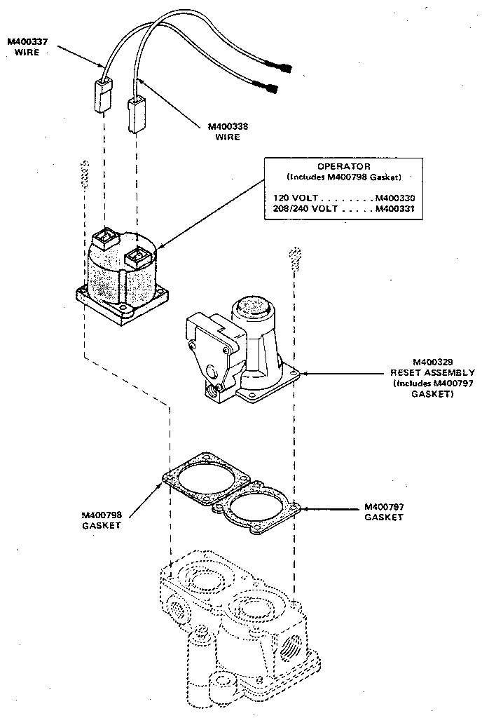
Gas valve actuator types manual standing pilot valve manually turned on and off for each heating cycle. These valves feature a manual valve (gas cock), inlet/outlet screens, pilot gas filter, and pilot adjustment key. Variety of gvd 6 wiring diagram. A typical standing pilot hookup with an added gas valve is shown in diagram a. Lennox thermostat wiring diagram nordyne furnace wiring diagram lennox wiring schematics furnace gas valve wiring diagram lennox furnace.
 Source: wiring89.blogspot.com
The g67 intermittent pilot ignition control is used to automatically light a pilot burner and energize the main burner gas valve of a heating system in response to the thermostats call for heat. While holding the tubing securely, slowly tighten fitting until you feel a slight “give”. Disconnect the valve from the gas manifold and the burner assembly. Thru no yes no 15 Disconnect the fryer from the gas and electrical power supplies.
 Source: manualsdir.com
Burner bracket q340 thermocouple propane bottle connector, regulator, hose & quick connect procedure 1. In this hvacr training video, i show how to wire the th, tr, and th/tr terminals on a combination gas valve. I discuss the flow of gas through the valve sole. Following a pain to remove, replace or fix the wiring in an automobile, having an accurate and detailed honeywell vs820 gas valve wiring. The g67 intermittent pilot ignition control is used to automatically light a pilot burner and energize the main burner gas valve of a heating system in response to the thermostats call for heat.
 Source: wiringall.com
Set meter to mv or volts dc place one lead to tp/th and place one lead to th In this hvacr training video, i show how to wire the th, tr, and th/tr terminals on a combination gas valve. Disconnect the pilot generator and operating thermostat wiring from the valve. Gas valve actuator types manual standing pilot valve manually turned on and off for each heating cycle. In this article, i am going to explain the function and wiring of the most common home �heat only� forced air / gas furnace with a standing pilot light) only need two wires for control.
 Source: skippingtheinbetween.blogspot.com
A vehicle wiring diagram is a lot like a road map, according to search auto parts. Voltage drop across the switch terminals burner on: Cummins marine fuel shutoff solenoid wiring 101. You want a heater that�s designed t. The gas is ignited by an igniter or a standing pilot.
 Source: schematron.org
Mount and wire controls per wiring diagram, page figure 1 4, and figure 1. Q refer to the wiring. Disconnect the valve from the gas manifold and the burner assembly. Lennox thermostat wiring diagram nordyne furnace wiring diagram lennox wiring schematics furnace gas valve wiring diagram lennox furnace. Field controls gas vent dampers gvd are made of stainless steel and is available in 8 sizes 4 through 10 and 12.
 Source: jimbutt.info
The third relay controls the heater. Field controls gas vent dampers gvd are made of stainless steel and is available in 8 sizes 4 through 10 and 12. Disconnect the pilot gas tube from the valve 4. Gas valve cross reference 9 standing pilot gas flow to the pilot burner is controlled by a safety valve which is manually operated and held in by current generated from a thermocouple placed in the pilot flame. This is assuming that the transformer is good and the high limit is closed.
Source: wiring89.blogspot.com
Mount and wire controls per wiring diagram, page figure 1 4, and figure 1. Set meter to mv or volts dc place one lead to tp/th and place one lead to th Video walks through the typical wiring of a basic standing pilot gas furnace. Disconnect the valve from the gas manifold and the burner assembly. This is assuming that the transformer is good and the high limit is closed.
 Source: google.de
Field controls gas vent dampers gvd are made of stainless steel and is available in 8 sizes 4 through 10 and 12. Mount and wire controls per wiring diagram, page figure 1 4, and figure 1. Ahe altitude conversion manual ( kb): Gas valve cross reference 9 standing pilot gas flow to the pilot burner is controlled by a safety valve which is manually operated and held in by current generated from a thermocouple placed in the pilot flame. A typical standing pilot hookup with an added gas valve is shown in diagram a.
![[DIAGRAM] Thermopile Gas Valve Wiring Diagram FULL Version [DIAGRAM] Thermopile Gas Valve Wiring Diagram FULL Version](https://ww2.justanswer.com/uploads/jcl8970/2010-01-31_035915_780-910_Schematic.jpg) Source: aandfwiring.dz-art.fr
Source: aandfwiring.dz-art.fr
*if higher than 35mv check connections and switch. When damper is fully open, main gas valve will open and main burners will ignite. Insert clean, deburred tubing all the way through the fitting. Install fitting into pilot gas outlet (see fig. Following a pain to remove, replace or fix the wiring in an automobile, having an accurate and detailed honeywell vs820 gas valve wiring.
 Source: wiringall.com
Control supplement — standing pilot boilers 1. The white rogers zone valves have three wires, white red and green. 2.mount the control so gas flow is in direction of arrow on bottom of control. In this article, i am going to explain the function and wiring of the most common home �heat only� forced air / gas furnace with a standing pilot light) only need two wires for control. Limit transformer pressure switch combustion fan l1 n r c 24 v 115 v black black black black orange orange green white
 Source: wiring88.blogspot.com
Q refer to the wiring. Verify that that module is securely grounded to the metal chassis of the fireplace. Limit transformer pressure switch combustion fan l1 n r c 24 v 115 v black black black black orange orange green white Wiring diagram a typical system wiring diagram is shown below. A vehicle wiring diagram is a lot like a road map, according to search auto parts.
Source: wiringdiagram99.blogspot.com
Limit transformer pressure switch combustion fan l1 n r c 24 v 115 v black black black black orange orange green white Damper must be fully open before main burners light. Disconnect the fryer from the gas and electrical power supplies. A professional understands basic electricity and electrical components and the sequence of operation for the typical standing pilot gas. The thermopile, energized by the pilot flame, generates sufficient power to operate the gas valve and on/off switch.
 Source: searspartsdirect.com
Wiring diagram for model cas 3 6 and 7 chimney vent two oil fired systems with cac 120 combustion air controller. Insert clean, deburred tubing all the way through the fitting. These additional terminals are not shown in this diagram.ahe; They include safety shutoff, a manual valve, a pressure regulator and pilot adjustment. Th tr and gas valve terminals wiring doityourself com robertshaw 700 720 series two stage valves for furnaces gray vr800 icg furnace residential heating units on a terminal troubleshooting intermittent ignition 4 diagrams 5 recommended spare sv9501m8129 u white rodgers fan limit figure 1 control installation faqs or circuit redundant modulating millivolt pilot.
This site is an open community for users to share their favorite wallpapers on the internet, all images or pictures in this website are for personal wallpaper use only, it is stricly prohibited to use this wallpaper for commercial purposes, if you are the author and find this image is shared without your permission, please kindly raise a DMCA report to Us.
If you find this site good, please support us by sharing this posts to your preference social media accounts like Facebook, Instagram and so on or you can also bookmark this blog page with the title standing pilot gas valve wiring diagram by using Ctrl + D for devices a laptop with a Windows operating system or Command + D for laptops with an Apple operating system. If you use a smartphone, you can also use the drawer menu of the browser you are using. Whether it’s a Windows, Mac, iOS or Android operating system, you will still be able to bookmark this website.
Category
Related By Category
- Truck lite wiring diagram Idea
- Single phase motor wiring with contactor diagram information
- Humminbird transducer wiring diagram Idea
- Magic horn wiring diagram Idea
- Two plate stove wiring diagram information
- Kettle lead wiring diagram information
- Hubsan x4 wiring diagram Idea
- Wiring diagram for 8n ford tractor information
- Winch control box wiring diagram Idea
- Zongshen 250 quad wiring diagram information