Split charge diode wiring diagram Idea
Home » Trend » Split charge diode wiring diagram Idea
Your Split charge diode wiring diagram images are available in this site. Split charge diode wiring diagram are a topic that is being searched for and liked by netizens today. You can Get the Split charge diode wiring diagram files here. Get all royalty-free photos.
If you’re searching for split charge diode wiring diagram images information related to the split charge diode wiring diagram topic, you have pay a visit to the right site. Our site always gives you hints for seeking the maximum quality video and image content, please kindly hunt and locate more enlightening video content and graphics that match your interests.
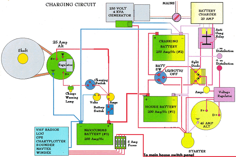
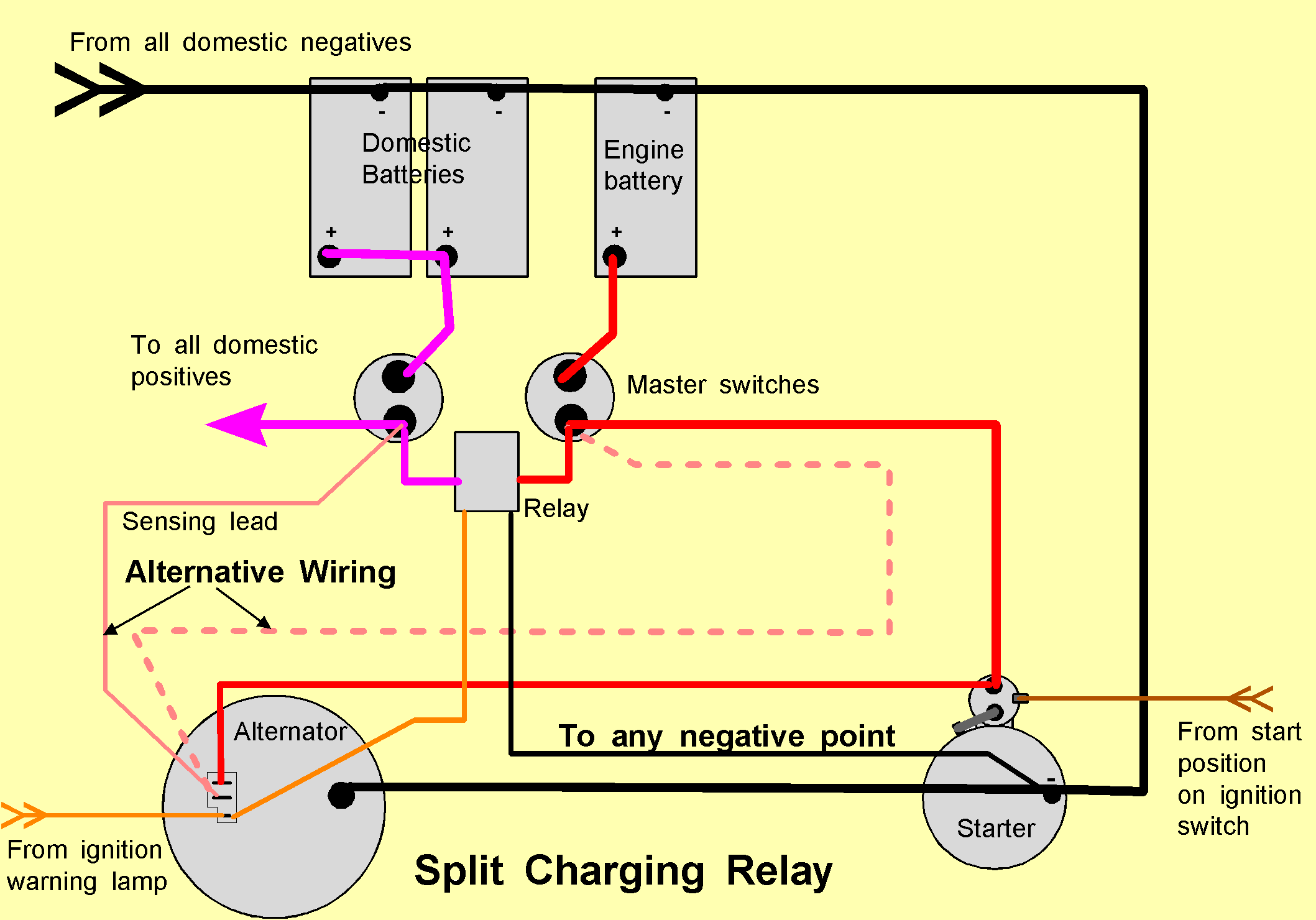
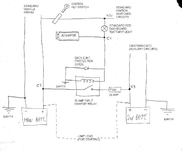
Split Charge Diode Wiring Diagram. Wiring in series, it goes from v(+) to the positive lead of the led, and then another led, then a 1k resistor to ground. In this mode it is called a split charge relay, or dual battery relay. For example, in this small project, we�re going to connect the protection diode in series with an led. The shockley diode equation relates the diode current of a p n junction diode to the diode voltage this relationship is the diode i v characteristic.
 Alternator Diode Wiring Diagram From wwwbloggercompinkcelebration.blogspot.com
So current can flow from the alternator (or other charging source, e.g. We have a laika ( italian ) there are lots of electronics that go with our cbe system. Narva 12 volt relay wiring diagram. Do something that will force the alternator to give maximum output. Split charging systems there are a number of split charging systems being offered to the 4x4 industry. In this mode it is called a split charge relay, or dual battery relay.
Wiring diagram book a1 15 b1 b2 16 18 b3 a2 b1 b3 15 supply voltage 16 18 l m h 2 levels b2 l1 f u 1 460 v f u 2 l2 l3 gnd h1 h3 h2 h4 f u 3 x1a f u 4 f u 5 x2a r power on optional x1 x2115 v 230 v h1 h3 h2 h4 optional connection electrostatically.
Several modern electronic devices like diodes eg. Since the reverse saturation current is is typically very small 10 9 to 10 15 a the expression. Personally i would correctly wire both charging systems and the use a heavy duty voltage sensitive relay to do the charge splitting. If the aux battery goes flat then the starter battery can still discharge through the diode into the aux. Battery charger voltage sensitive relay split charge diode wiring diagram png 1000x1000px ampere. However, the charging circuit requires a minimum of a 2.5mm square cable as does the fridge circuit.
 Source: angelina-jolie-2012.blogspot.com
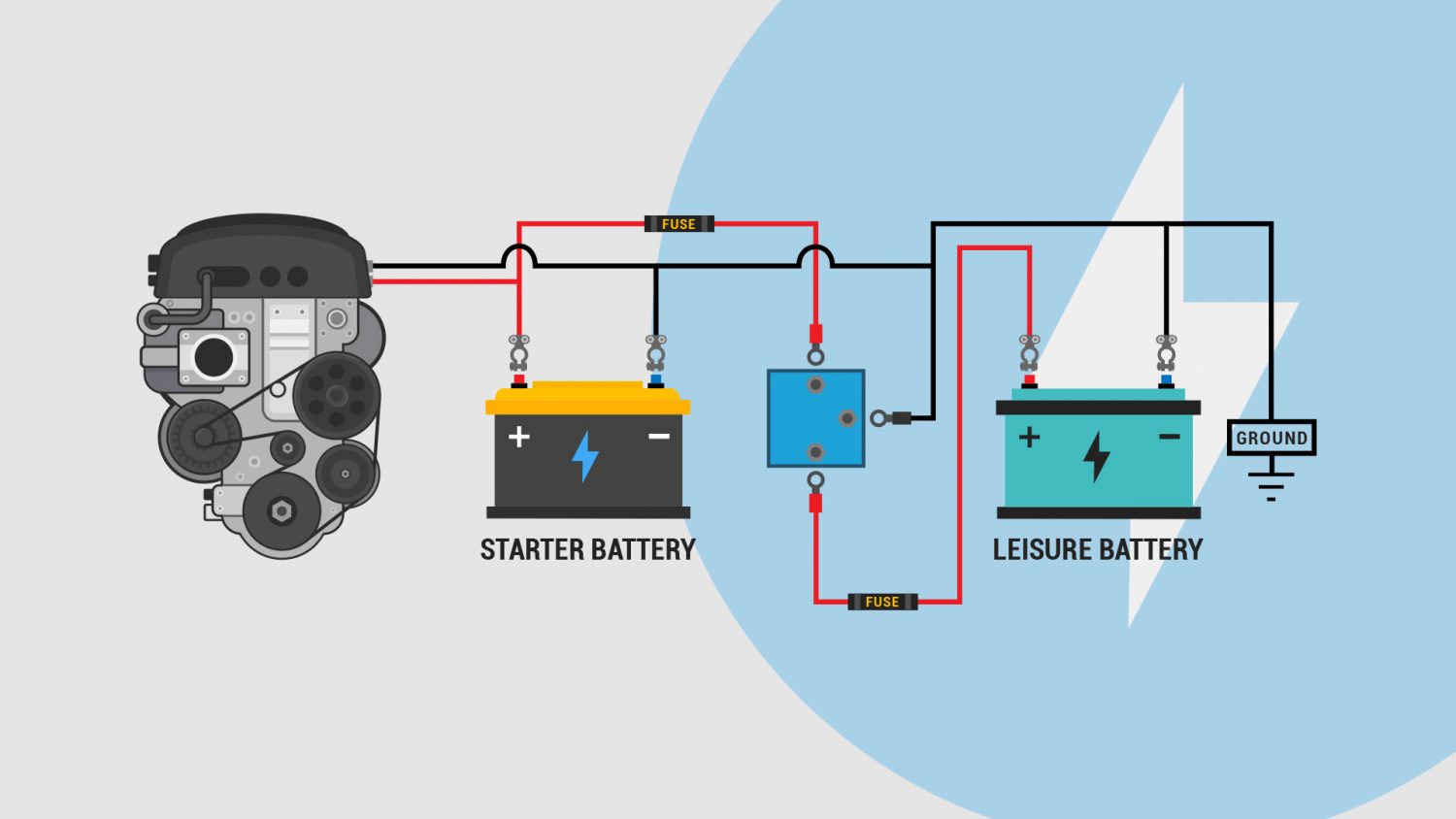
If you look at the wiring diagrams above, you will also see that there are a number of neutral or earth cables. Battery charger ) to both batteries but cannot flow between batteries, thereby isolating the starter battery from the leisure battery and preventing it being flattened. Most of these types of splitters contain two separate diodes which, when connected to an alternator, split the charge in two and deliver it to two separate batteries which are totally isolated from each other. Wiring diagram comes with a number of easy to follow wiring diagram guidelines. Personally i would correctly wire both charging systems and the use a heavy duty voltage sensitive relay to do the charge splitting.

If the aux battery goes flat then the starter battery can still discharge through the diode into the aux. Wiring diagram comes with a number of easy to follow wiring diagram guidelines. For example, in this small project, we�re going to connect the protection diode in series with an led. However, the charging circuit requires a minimum of a 2.5mm square cable as does the fridge circuit. Using 12 volt switching devices only for primary activation note.
 Source: vanlifeadventure.com
I thought you were using a relay based split charge system (?) so the problems that adverc get around as a result of the diode based split charge problems don�t exist. In this mode it is called a split charge relay, or dual battery relay. Personally i would correctly wire both charging systems and the use a heavy duty voltage sensitive relay to do the charge splitting. On a split charge relay, blocking diode system or with a single battery bank; If you look at the wiring diagrams above, you will also see that there are a number of neutral or earth cables.
 Source: ybw.com
These are our most commonly requested wiring diagrams suitable for typical. Split charging systems there are a number of split charging systems being offered to the 4x4 industry. The diagrams below are intended as an overview and some details are missing from them. This will have close to zero voltdrop and will react to voltage rise so it will split both the alternator and solar charge. I wired them with the positive on the right, moving to ground on the left.

24 and 36 volt wiring diagrams. If the aux battery goes flat then the starter battery can still discharge through the diode into the aux. So current can flow from the alternator (or other charging source, e.g. Mitsubishi mini split wiring diagram. I created six distinct rows, and two columns of leds.
 Source: vanlifeadventure.com
Using 12 volt switching devices only for primary activation note. You could use either diagram. Battery charger wiring diagram management system relay png 1472x1269px ampere area campervan split charging a helpful ilrated guide vanlife adventure 500amp mobile audio relay continuous battery isolator 500a online in turkey b082hmdmlg Split charging systems there are a number of split charging systems being offered to the 4x4 industry. These are our most commonly requested wiring diagrams suitable for typical.

Battery charger wiring diagram management system relay png 1472x1269px ampere area campervan split charging a helpful ilrated guide vanlife adventure 500amp mobile audio relay continuous battery isolator 500a online in turkey b082hmdmlg Split charging systems there are a number of split charging systems being offered to the 4x4 industry. This will have close to zero voltdrop and will react to voltage rise so it will split both the alternator and solar charge. Using 12 volt switching devices only for primary activation note. 24 and 36 volt wiring diagrams.
 Source: daggdroppe.se
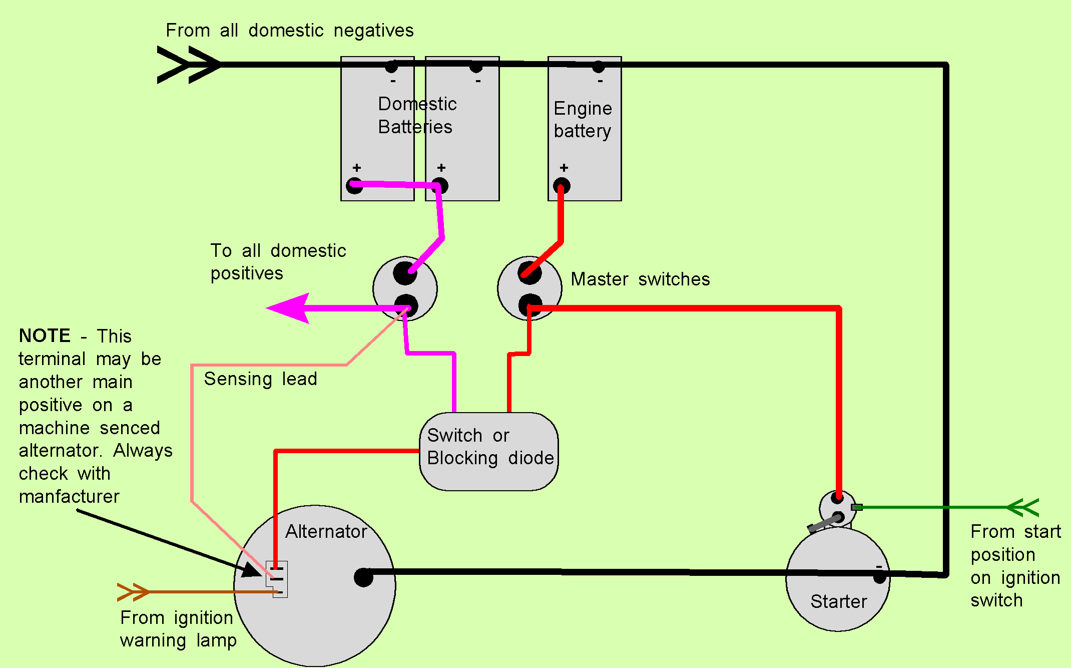
If you look at the wiring diagrams above, you will also see that there are a number of neutral or earth cables. This split charging method utilises the property of diodes to allow current to flow only in one direction. Narva 12 volt relay wiring diagram. Several modern electronic devices like diodes eg. 17 battery connector and charging cable verify that the connectors on both the battery and the charger are attached so that the positive.
 Source: tb-training.co.uk
17 battery connector and charging cable verify that the connectors on both the battery and the charger are attached so that the positive. Here at rayne automotive and in the world of charging in general there are three main split charge types. All battery circuit including battery charger wiring diagram. The diode type battery isolator uses semiconductor diodes to split the current from the alternator or generator and charge 2 or more batteries at the same time. Battery charger wiring diagram management system relay png 1472x1269px ampere area campervan split charging a helpful ilrated guide vanlife adventure 500amp mobile audio relay continuous battery isolator 500a online in turkey b082hmdmlg

This split charging method utilises the property of diodes to allow current to flow only in one direction. For example, in this small project, we�re going to connect the protection diode in series with an led. In this project we have designed a simple 230v led driver circuit which can drive led directly from the mains supply. Many battery powered devices use two aa alkaline cells. An led is pretty sensitive to current in the reverse direction.
 Source: funnyhacklife.blogspot.com
All battery circuit including battery charger wiring diagram. Battery charger wiring diagram management system relay png 1472x1269px ampere area campervan split charging a helpful ilrated guide vanlife adventure 500amp mobile audio relay continuous battery isolator 500a online in turkey b082hmdmlg Mitsubishi mini split wiring diagram. Wiring diagram of car charging system wiring diagram line wiring diagram. An led is pretty sensitive to current in the reverse direction.
 Source: wiring89.blogspot.com
These are our most commonly requested wiring diagrams suitable for typical. One battery is used to start the engine and the other is used to run the accessories. Disconnect the lead that goes from the back of the alternator down to the starter solenoid at the solenoid end and connect it to the diode charge in terminal then connect a charge lead from the charge out terminals on the diode, one to each battery (bank). The diode battery isolator the diode type battery isolator uses semiconductor diodes to split the current from the alternator or generator and charge 2 or more batteries at the same time. Narva 12 volt relay wiring diagram.
 Source: aidinhaaveita.blogspot.com
This will have close to zero voltdrop and will react to voltage rise so it will split both the alternator and solar charge. Here at rayne automotive and in the world of charging in general there are three main split charge types. So current can flow from the alternator (or other charging source, e.g. We have a laika ( italian ) there are lots of electronics that go with our cbe system. On a split charge relay, blocking diode system or with a single battery bank;
 Source: tb-training.co.uk
Do something that will force the alternator to give maximum output. You could use either diagram. Here at rayne automotive and in the world of charging in general there are three main split charge types. 24 and 36 volt wiring diagrams. This will depend what it is charging.
 Source: niqqay-lunnia.blogspot.com
Pac 200 battery isolator wiring diagram. These are our most commonly requested wiring diagrams suitable for typical. Several modern electronic devices like diodes eg. Narva 12 volt relay wiring diagram. Diode battery isolators allow simultaneous charging of two or more batteries from one alternator, without connecting the batteries together.
 Source: tops-stars.com
All battery circuit including battery charger wiring diagram. Disconnect the lead that goes from the back of the alternator down to the starter solenoid at the solenoid end and connect it to the diode charge in terminal then connect a charge lead from the charge out terminals on the diode, one to each battery (bank). We have a laika ( italian ) there are lots of electronics that go with our cbe system. Spotlight wiring diagram uk staggering pin relay the experience led lights whelen lights led light bars wiring diagram trailer plugs and sockets. Mitsubishi mini split wiring diagram.
 Source: ejames.co.uk
On the smallest alternator split this with a split charge diode between the engine battery and the domestic (and any other battery bank) and add another advanced regulator to it. An led is pretty sensitive to current in the reverse direction. Many battery powered devices use two aa alkaline cells. Put simply, a diode allows current to flow in only one direction. 24 and 36 volt wiring diagrams.
 Source: vanguard-conversions.co.uk
One battery is used to start the engine and the other is used to run the accessories. Disconnect the lead that goes from the back of the alternator down to the starter solenoid at the solenoid end and connect it to the diode charge in terminal then connect a charge lead from the charge out terminals on the diode, one to each battery (bank). Most of these types of splitters contain two separate diodes which, when connected to an alternator, split the charge in two and deliver it to two separate batteries which are totally isolated from each other. These are our most commonly requested wiring diagrams suitable for typical. An led is pretty sensitive to current in the reverse direction.
This site is an open community for users to share their favorite wallpapers on the internet, all images or pictures in this website are for personal wallpaper use only, it is stricly prohibited to use this wallpaper for commercial purposes, if you are the author and find this image is shared without your permission, please kindly raise a DMCA report to Us.
If you find this site value, please support us by sharing this posts to your preference social media accounts like Facebook, Instagram and so on or you can also save this blog page with the title split charge diode wiring diagram by using Ctrl + D for devices a laptop with a Windows operating system or Command + D for laptops with an Apple operating system. If you use a smartphone, you can also use the drawer menu of the browser you are using. Whether it’s a Windows, Mac, iOS or Android operating system, you will still be able to bookmark this website.
Category
Related By Category
- Predator 670 engine wiring diagram Idea
- Frsky x8r wiring diagram information
- Pioneer ts wx130da wiring diagram Idea
- Johnson 50 hp wiring diagram Idea
- Kohler voltage regulator wiring diagram Idea
- Johnson 50 hp outboard wiring diagram information
- Kti hydraulic remote wiring diagram Idea
- Pyle plpw12d wiring diagram information
- Tx9600ts wiring diagram information
- Lifan 50cc wiring diagram information