Snes controller wiring diagram information
Home » Trend » Snes controller wiring diagram information
Your Snes controller wiring diagram images are ready in this website. Snes controller wiring diagram are a topic that is being searched for and liked by netizens now. You can Find and Download the Snes controller wiring diagram files here. Get all free vectors.
If you’re searching for snes controller wiring diagram pictures information connected with to the snes controller wiring diagram interest, you have visit the right blog. Our site always provides you with hints for downloading the highest quality video and image content, please kindly hunt and locate more informative video articles and images that match your interests.
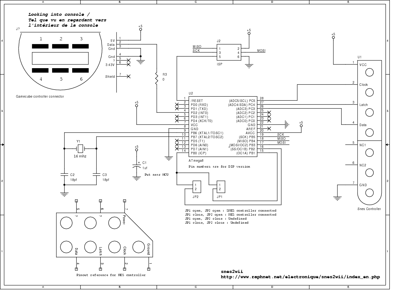
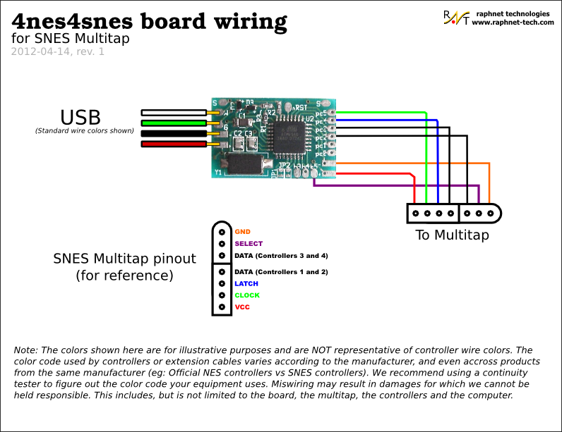
Snes Controller Wiring Diagram. Pcb for 4 snes controllers: The simple goal in wiring is to have the grounds and signals of each device linked to the ground and. Read snes controller wiring diagram pdf on our digital library. Many clones also use this convention too, but not all.
 Arcade style controller for Snes, NES and PC From raphnet.net
We got a diagram for the wires from a website, which i can�t recall which, but the diagram looked like this: The writers of snes controller wiring diagram have made all reasonable attempts to offer latest and precise information and facts for the readers of this publication. Raspberry pi stack exchange is a question and answer site for users and developers of hardware and software for raspberry pi. It came from a yobo f. Brown (ground) and white (5v). There are 5 wires that i soldered directly to some of the ports, following this diagram:
Controllers that do not work on the original system will not work with the retrokit.
On nes controller wiring diagram. The dreamkatz controller wire wrap according the diagram on the right. (note that the snes and nes color codes are different). Sign up to join this community. Learn to solder correctly and use the right controller for the chip. On nes controller wiring diagram.
 Source: schematron.org
Be careful as there are tiny wires for the �side� buttons so just make sure those pieces come out cleanly. (note that the snes and nes color codes are different). My first idea was to read the nes controller presses with arduino and don�t connect any of the nes wires adjacent to a communication pin. The writers of snes controller wiring diagram have made all reasonable attempts to offer latest and precise information and facts for the readers of this publication. Wired controller for nintendo switch gamecube style black powera.
 Source: raphnet-tech.com
Hopefully the following timing diagram will serve to illustrate this. Learn to solder correctly and use the right controller for the chip. Two of the three remaining wires are used by the snes to output clock and timing information: Schematics for consoles are notoriously hard to come by. (s)nes wiring diagram n64 wiring diagram when using the multiuse tiny1 pcb for this project, only the following components are needed.
 Source: raphnet.net
Once you lift the back off, you can remove the pcb. Or rev3 console if you have no way of checking the motherboard). See the ic in plain sight along with the wires connecting to the cable. The snes pad works exactly the same as the nes controller, except it has two 4021s inside, and there are sixteen pulses on the clk line, and sixteen bits of data come out the data line.as a matter of fact, a snes pad can be connected to a nes by simply swapping the connector on the end. On nes controller wiring diagram.
 Source: raphnet-tech.com
I am unsure how to connect the snes�s controller wires to the pi zero�s gpio. Part 1 of our hardware teardown of the evolution of nintendo controllers. It only takes a minute to sign up. Brown (ground) and white (5v). Supports n64 controllers (official and most 3rd party, including the hori mini) support for gamecube controllers.
 Source: raphnet.net
Or rev3 console if you have no way of checking the motherboard). Sign up to join this community. If your controller uses the standard color code, you can follow the diagram on the right. See the ic in plain sight along with the wires connecting to the cable. There are 5 small phillips screws on the back.
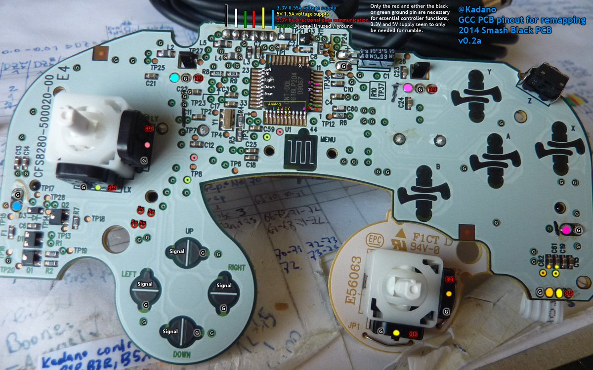 Source: kovodym.blogspot.com
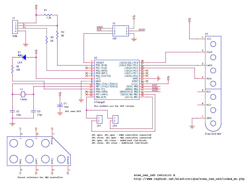
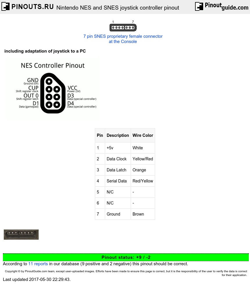
Our idea was to implement or controller with the rpi through the gpio pins. 4.2) soldering snes controller wires as far as i am aware, nintendo brand controllers all use the same color code. You can read snes controller wiring diagram pdf direct on your mobile phones or pc. Be careful as there are tiny wires for the �side� buttons so just make sure those pieces come out cleanly. Let�s start by looking at the snes controller pinout:
 Source: misdankariyah.blogspot.com
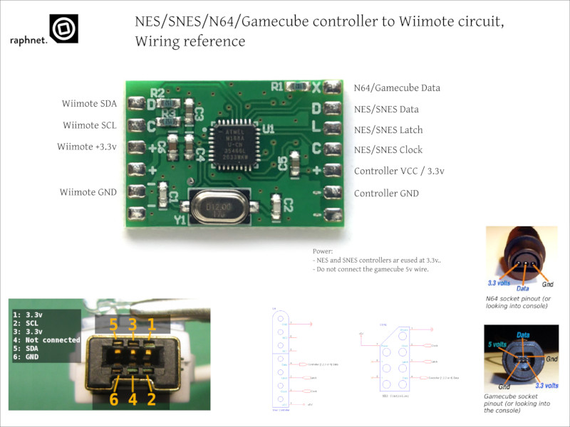
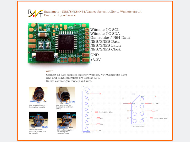
It�s also helping me learn how to use the schematic capture software that i. Brown (ground) and white (5v). Nes/snes/n64/gamecube controller to wiimote circuit. Pcb for 4 snes controllers: Raspberry pi stack exchange is a question and answer site for users and developers of hardware and software for raspberry pi.
 Source: howchoo.com
As you can see the snes has two gamepad ports which each have 5 wires. You can read snes controller wiring diagram pdf direct on your mobile phones or pc. Data for all other buttons is driven at the rising edge of clock. Hopefully the following timing diagram will serve to illustrate this. Use a known good controller.
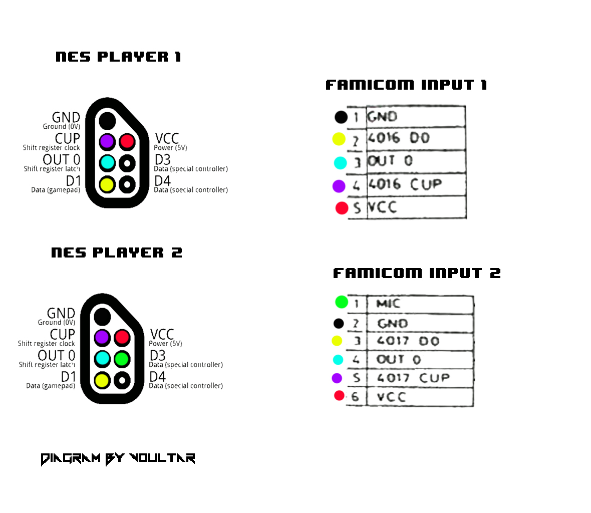 Source: schematron.org
See the ic in plain sight along with the wires connecting to the cable. We�ll begin by disassembling the snes controller. Suggested digikey part numbers are included: Data for all other buttons is driven at the rising edge of clock. Nintendo 64 av cable wiring diagram schematic diagrams snes scart hd png 1300x700 1059106 pngfind any one have ninty switch mobo schematics gbatemp net the independent game community github dekunukem nintendo switch reverse engineering a look at inner workings of joycon and
 Source: wiringall.com
Suggested digikey part numbers are included: We got a diagram for the wires from a website, which i can�t recall which, but the diagram looked like this: The writers of snes controller wiring diagram have made all reasonable attempts to offer latest and precise information and facts for the readers of this publication. This is a schematic of how the nes controller looks on the inside. When figuring out which wires correspond to which pins on the controller port, do not trust any color diagrams you find online.
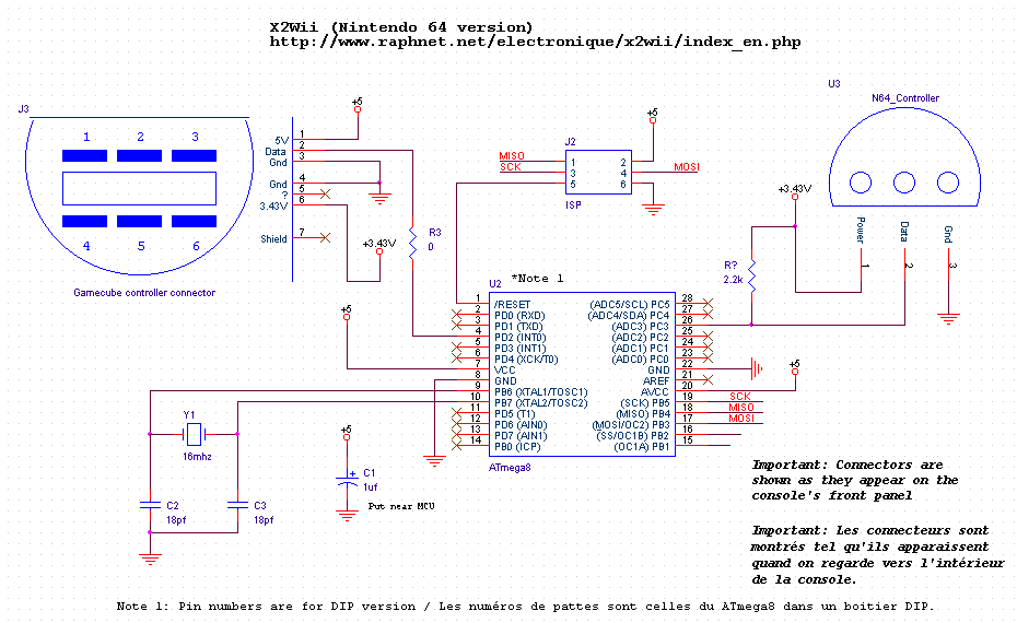 Source: wiring121.blogspot.com
Sign up to join this community. It came from a yobo f. Let�s start by looking at the snes controller pinout: Recall that p41 is wired wrapped to.pcb and wiring a pcb from another source can be used in replacing the electronics in a standard device, or giving communications to a custom controller. If your controller uses the standard color code, you can follow the diagram on the right.
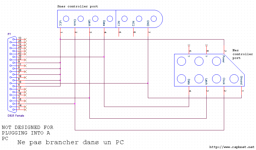 Source: schematron.org
Optional 1, 2, 3, 4,or 5 snes controller extension cords, so you don�t mod directly to the pad and a snes controller along with the necessary solder, soldering iron, and a knife or wire stripper for this i used the diagram shown here, it is a mirror of the original ziplabel.com directpadpro guide and driver page, as the original no longer is up. When figuring out which wires correspond to which pins on the controller port, do not trust any color diagrams you find online. Two of the three remaining wires are used by the snes to output clock and timing information: The creators will not be held accountable for any unintentional flaws or omissions that may be found. Read snes controller wiring diagram pdf on our digital library.
 Source: tops-stars.com
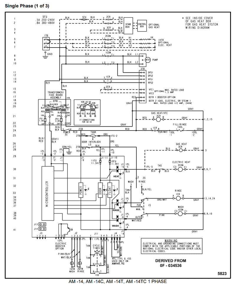
The writers of snes controller wiring diagram have made all reasonable attempts to offer latest and precise information and facts for the readers of this publication. Controllers that do not work on the original system will not work with the retrokit. Multiple revision ntsc schematic from schematron.org y/c video exists at the rgb encoder on the snes 2 units, but nintendo decided not to. (note that the snes and nes color codes are different). Once you lift the back off, you can remove the pcb.
 Source: poorstudenthobbyist.blogspot.com
Nes/snes/n64/gamecube controller to wiimote circuit. Let�s start by looking at the snes controller pinout: Be careful as there are tiny wires for the �side� buttons so just make sure those pieces come out cleanly. This is where almost all problems occur. We got a diagram for the wires from a website, which i can�t recall which, but the diagram looked like this:
 Source: wiringall.com
If your controller uses the standard color code, you can follow the diagram on the right. Many clones also use this convention too, but not all. Hopefully the following timing diagram will serve to illustrate this. Snes controller (10 usd on ebay) brief explanation: The snes controllers drive data for the first button at the falling edge of latch.
 Source: pinouts.ru
See the ic in plain sight along with the wires connecting to the cable. We�ll begin by disassembling the snes controller. Optional 1, 2, 3, 4,or 5 snes controller extension cords, so you don�t mod directly to the pad and a snes controller along with the necessary solder, soldering iron, and a knife or wire stripper for this i used the diagram shown here, it is a mirror of the original ziplabel.com directpadpro guide and driver page, as the original no longer is up. Nintendo 64 av cable wiring diagram schematic diagrams snes scart hd png 1300x700 1059106 pngfind any one have ninty switch mobo schematics gbatemp net the independent game community github dekunukem nintendo switch reverse engineering a look at inner workings of joycon and Controllers that do not work on the original system will not work with the retrokit.
 Source: schematron.org
If your controller uses the standard color code, you can follow the diagram on the right. Be careful as there are tiny wires for the �side� buttons so just make sure those pieces come out cleanly. I am unsure how to connect the snes�s controller wires to the pi zero�s gpio. The retrokit is only designed for one controller. Pcb for 4 snes controllers:
 Source: raphnet-tech.com
Some nes controllers seem to have the red wire as data. Let�s start by looking at the snes controller pinout: Multiple revision ntsc schematic from schematron.org y/c video exists at the rgb encoder on the snes 2 units, but nintendo decided not to. My first idea was to read the nes controller presses with arduino and don�t connect any of the nes wires adjacent to a communication pin. The writers of snes controller wiring diagram have made all reasonable attempts to offer latest and precise information and facts for the readers of this publication.
This site is an open community for users to submit their favorite wallpapers on the internet, all images or pictures in this website are for personal wallpaper use only, it is stricly prohibited to use this wallpaper for commercial purposes, if you are the author and find this image is shared without your permission, please kindly raise a DMCA report to Us.
If you find this site serviceableness, please support us by sharing this posts to your preference social media accounts like Facebook, Instagram and so on or you can also bookmark this blog page with the title snes controller wiring diagram by using Ctrl + D for devices a laptop with a Windows operating system or Command + D for laptops with an Apple operating system. If you use a smartphone, you can also use the drawer menu of the browser you are using. Whether it’s a Windows, Mac, iOS or Android operating system, you will still be able to bookmark this website.
Category
Related By Category
- Predator 670 engine wiring diagram Idea
- Frsky x8r wiring diagram information
- Pioneer ts wx130da wiring diagram Idea
- Johnson 50 hp wiring diagram Idea
- Kohler voltage regulator wiring diagram Idea
- Johnson 50 hp outboard wiring diagram information
- Kti hydraulic remote wiring diagram Idea
- Pyle plpw12d wiring diagram information
- Tx9600ts wiring diagram information
- Lifan 50cc wiring diagram information