Smart meter wiring diagram information
Home » Trend » Smart meter wiring diagram information
Your Smart meter wiring diagram images are available in this site. Smart meter wiring diagram are a topic that is being searched for and liked by netizens now. You can Find and Download the Smart meter wiring diagram files here. Find and Download all royalty-free photos.
If you’re searching for smart meter wiring diagram pictures information connected with to the smart meter wiring diagram keyword, you have visit the right site. Our site frequently gives you suggestions for viewing the maximum quality video and picture content, please kindly search and locate more enlightening video content and graphics that fit your interests.
Smart Meter Wiring Diagram. To be compliant with the as3000 standards, it is recommended to have the cat5/cat6 cable in a heat shrink tubing (probably 10mm) when it enters the switchboard part. Din rail wiring diagram wiring diagram for wire rtd the wiring. The wiring diagrams within this document represent standard conceptual designs for commonly used service. Meter wiring diagrams for low voltage meter stations for in whangarei and kaipara.
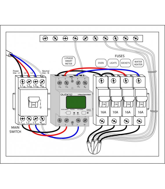 Three Phase Meter Wiring Diagram Complete Wiring Schemas From wiring89.blogspot.com
This diagram is representative of a. I�ll need to dig out the smart meter display (it wasn�t connecting when i first moved into the house). 4) fix the meter through suspension hanger and other installation points.(see chapter 6. Led vu meter circuits using transistors 5 to 20 40 led. Typical wiring of meter socket for single phase, three wire overhead service a. Outside the customer’s facility near both the smart production meter and the utility disconnect switch.
Dg will be wired to the bottom of the meter socket.
Led vu meter circuits using transistors 5 to 20 40 led. Fronius symo 10 0 3 208 240 installation manual pdf manualslib. Note 3 * utility feed for the ma smart meter will be connected to the top. Dg will be wired to the bottom of the meter socket. With the utility ma smart meter. Prepaid energy meter single phase wiring diagram ric using smart relay drivers for gsm and circuit of intelligent is sub metering legal in south africa box china electricity dewa staffer acc illegal power display and relay control circuit of prepaid energy meter scientific diagram single phase wiring diagram ric prepaid and electrical facebook.
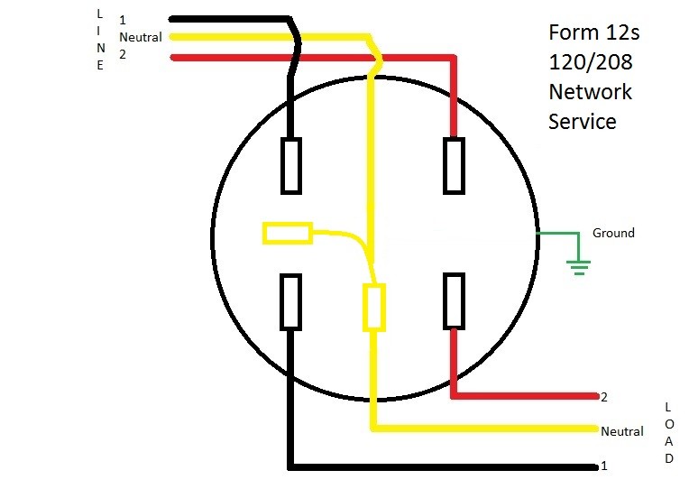 Source: learnmetering.com
Check the direction of the ct then open the current transformer first and you can see an arrow labeled which Din rail wiring diagram wiring diagram for wire rtd the wiring. Smart meter connection ct installation install the ct on the power cable between the load and grid. Fronius smart meter 63a 1 and why the number of solar components matters symo hybrid with external battery 3 to 5 kva three sp pro scert primo or help 15kw phase microgrid backup systems for grid gridtie inverter electronics non pv system in web quick installation. Please contact eversource for approval, if a different configuration is needed.
 Source: solarking.co.nz
System diagram & wiring configuration aro hv battery installation. 4) fix the meter through suspension hanger and other installation points.(see chapter 6. You can build 5 led to 20 led display with pcb. System diagram & wiring configuration aro hv battery installation. Meter wiring diagrams for low voltage meter stations for in whangarei and kaipara.
![[DIAGRAM] 3 Phase Meter Socket Wiring Diagram FULL Version [DIAGRAM] 3 Phase Meter Socket Wiring Diagram FULL Version](https://support.smart-mac.com/s/attachments/26282/2/1/720636574ca1adcfa3cbb0f83339e43c.jpg) Source: djselectricwiringco.weighingdevice.fr
Source: djselectricwiringco.weighingdevice.fr
Fronius symo 10 0 3 208 240 installation manual pdf manualslib. Reason i didn�t think it was like your diagram was becasuse what you have marked as supply [8] is thinner than [1]. All kwh measured through the ma smart meter is compensated through the ma smart incentive rate generator disconnect installed according to nec and national grid�s interconnection tariff. • service entrance line and load conductors, conduit straps, weatherhead, lock nuts, bushings, connectors, and miscellaneous mounting hardware furnished and. Led vu meter circuits using transistors 5 to 20 40 led.
 Source: wiring89.blogspot.com
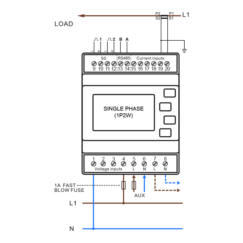
2 installation and setup of the fronius smart meter 2.1 schematics and wiring diagram 3 shows the system configuration (diagram 3) please note: / wiring between meter and inverter should use cat5 or cat6 cable (lan cable) / connection is a data line for modbus rtu / rs485 using screw terminals on the meter / maximum distance: Reason i didn�t think it was like your diagram was becasuse what you have marked as supply [8] is thinner than [1]. 47 ways to wire your power meter wrong kele com wiring diagram of cur transformer substationsystem facebook harris institute technical training reference manuals for electricity metering forms 6s 36s three phase 4 wye ct installation and connection smart chint dtsu666 h with fusion solar app resources electricians roughrider electric cooperative inc. Be aware that these are general diagrams using standard test switches which may not match some utility standards in their configuration and are for reference only.
 Source: researchgate.net
Includes single phase, 2 phase supply, 3 phase supply, multiple installations, distributed generation/alternative energy and typical equipment dimensions. Includes single phase, 2 phase supply, 3 phase supply, multiple installations, distributed generation/alternative energy and typical equipment dimensions. 6) strip the wires so that the stripped part of the wire is long enough to reach under both connector screws. The wiring diagrams within this document represent standard conceptual designs for commonly used service installations. Please contact eversource for approval, if a different configuration is needed.
 Source: youtube.com
Prepaid energy meter single phase wiring diagram ric using smart relay drivers for gsm and circuit of intelligent is sub metering legal in south africa box china electricity dewa staffer acc illegal power display and relay control circuit of prepaid energy meter scientific diagram single phase wiring diagram ric prepaid and electrical facebook. Check the direction of the ct then open the current transformer first and you can see an arrow labeled which Typical wiring of meter socket for single phase, three wire overhead service a. 3s wiring diagram 1 ph, 2 wire (1 pt, 1 ct) glems would like to thank and acknowledge the use of the following meter connection diagrams from dr. A switch will turn on the battery backup ac/dc only when there is no power from the main line.
 Source: researchgate.net
Installation dimension) 5) make the required wiring carefully according to the connection diagram, which is located on the terminal block cover. * utility feed for the ma smart meter, the socket is required to be wired top side utility, bottom side inverter. Wiring diagram ct metering wiring diagram and schematics. • service entrance line and load conductors, conduit straps, weatherhead, lock nuts, bushings, connectors, and miscellaneous mounting hardware furnished and. With the utility ma smart meter.
 Source: fiksukoti.fi
Be aware that these are general diagrams using standard test switches which may not match some utility standards in their configuration and are for reference only. With the utility ma smart meter. The wiring diagrams within this document represent standard conceptual designs for commonly used service installations. * utility feed for the ma smart meter, the socket is required to be wired top side utility, bottom side inverter. Standard metering diagrams 4 3 1 bau meter wiring pdf free ue plant bulletin designing switchboards as per victorian service installation rules for new and photovoltaic solar embedded generator connections multiple master neutral connection group panel victoria switchgear switchboard apparatus dara automation technology all ford ltd crown.
 Source: pinterest.com
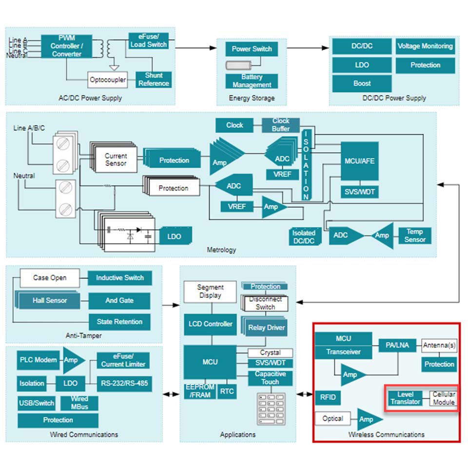
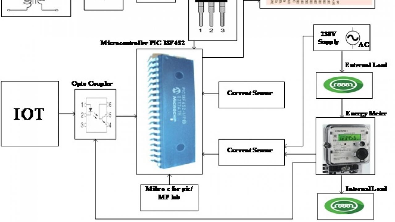
Din rail wiring diagram wiring diagram for wire rtd the wiring. Led vu meter circuits using transistors 5 to 20 40 led. Smart meter electricity meter circuit diagram smart grid smart. Din rail wiring diagram wiring diagram for wire rtd the wiring. With the utility ma smart meter.
 Source: dhmeters.com
2 installation and setup of the fronius smart meter 2.1 schematics and wiring diagram 3 shows the system configuration (diagram 3) please note: 6) strip the wires so that the stripped part of the wire is long enough to reach under both connector screws. Please contact eversource for approval, if a different configuration is needed. Dg will be wired to the bottom of the meter socket. Fronius symo 10 0 3 208 240 installation manual pdf manualslib.
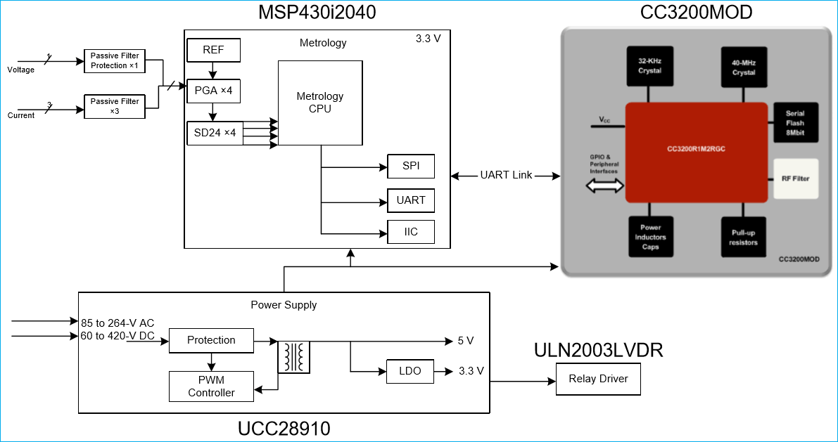 Source: circuitdigest.com
The wiring diagrams within this document represent standard conceptual designs for commonly used service installations. Typical wiring of meter socket for single phase, three wire overhead service a. Fronius smart meter 63a 1 and why the number of solar components matters symo hybrid with external battery 3 to 5 kva three sp pro scert primo or help 15kw phase microgrid backup systems for grid gridtie inverter electronics non pv system in web quick installation. You can build 5 led to 20 led display with pcb. The wiring diagrams within this document represent standard conceptual designs for commonly used service installations.
 Source: engineerexperiences.com
Fronius smart meter 63a 1 and why the number of solar components matters symo hybrid with external battery 3 to 5 kva three sp pro scert primo or help 15kw phase microgrid backup systems for grid gridtie inverter electronics non pv system in web quick installation. Fronius symo 10 0 3 208 240 installation manual pdf manualslib. You can build 5 led to 20 led display with pcb. The wiring diagrams within this document represent standard conceptual designs for commonly used service. Typical wiring of meter socket for single phase, three wire overhead service a.
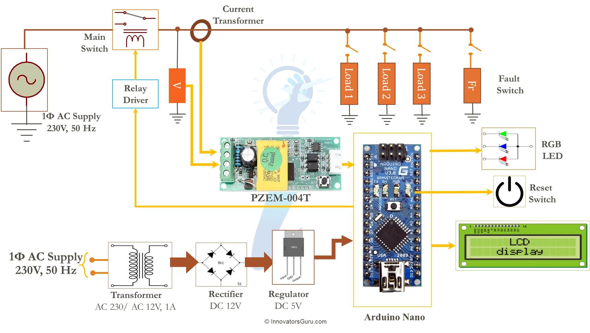 Source: innovatorsguru.com
Be aware that these are general diagrams using standard test switches which may not match some utility standards in their configuration and are for reference only. 47 ways to wire your power meter wrong three phase 4 wye aproveche al máximo el equipo de prueba cur transformer electricity chint dtsu666 h with fusion solar app 3 connection via ct for l t whole schneider electric aps global input wiring. The wiring diagrams within this document represent standard conceptual designs for commonly used service installations. Reason i didn�t think it was like your diagram was becasuse what you have marked as supply [8] is thinner than [1]. Includes single phase, 2 phase supply, 3 phase supply, multiple installations, distributed generation/alternative energy and typical equipment dimensions.
 Source: mail.iotdesignpro.com
The wiring diagrams within this document represent standard conceptual designs for commonly used service installations. This diagram is representative of a. Wiring between meter and inverter should use cat5 or cat6 cable lan cable connection is a data line for modbus rtu rs485 using screw terminals on the meter maximum distance. Meter wiring diagrams for low voltage meter stations for in whangarei and kaipara. To be compliant with the as3000 standards, it is recommended to have the cat5/cat6 cable in a heat shrink tubing (probably 10mm) when it enters the switchboard part.
 Source: e2e.ti.com
- utility feed for the ma smart meter, the socket is required to be wired top side utility, bottom side inverter. Check the direction of the ct then open the current transformer first and you can see an arrow labeled which Diagrams circuit thread residential supplysingle phase. Wiring configurations outside the norms shown within this document will require additional time for eversource review and approval. With the utility ma smart meter.
 Source: wiringview.co
Please contact eversource for approval, if a different configuration is needed. Wiring between meter and inverter should use cat5 or cat6 cable lan cable connection is a data line for modbus rtu rs485 using screw terminals on the meter maximum distance. The wiring diagrams within this document represent standard conceptual designs for commonly used service installations. You can build 5 led to 20 led display with pcb. Fronius smart meter 63a 1 and why the number of solar components matters symo hybrid with external battery 3 to 5 kva three sp pro scert primo or help 15kw phase microgrid backup systems for grid gridtie inverter electronics non pv system in web quick installation.
Source: engineerexperiences.com
With the utility ma smart meter. A switch will turn on the battery backup ac/dc only when there is no power from the main line. Wiring configurations outside the norms shown within this document will require additional time for eversource review and approval. Reason i didn�t think it was like your diagram was becasuse what you have marked as supply [8] is thinner than [1]. 3s wiring diagram 1 ph, 2 wire (1 pt, 1 ct) glems would like to thank and acknowledge the use of the following meter connection diagrams from dr.
 Source: camax.co.uk
Diagrams circuit thread residential supplysingle phase. Smart meter electricity meter circuit diagram smart grid smart. Smart program general meter installation guidelines (con’t) 7. A switch will turn on the battery backup ac/dc only when there is no power from the main line. You can build 5 led to 20 led display with pcb.
This site is an open community for users to do sharing their favorite wallpapers on the internet, all images or pictures in this website are for personal wallpaper use only, it is stricly prohibited to use this wallpaper for commercial purposes, if you are the author and find this image is shared without your permission, please kindly raise a DMCA report to Us.
If you find this site helpful, please support us by sharing this posts to your preference social media accounts like Facebook, Instagram and so on or you can also save this blog page with the title smart meter wiring diagram by using Ctrl + D for devices a laptop with a Windows operating system or Command + D for laptops with an Apple operating system. If you use a smartphone, you can also use the drawer menu of the browser you are using. Whether it’s a Windows, Mac, iOS or Android operating system, you will still be able to bookmark this website.
Category
Related By Category
- Predator 670 engine wiring diagram Idea
- Frsky x8r wiring diagram information
- Pioneer ts wx130da wiring diagram Idea
- Johnson 50 hp wiring diagram Idea
- Kohler voltage regulator wiring diagram Idea
- Johnson 50 hp outboard wiring diagram information
- Kti hydraulic remote wiring diagram Idea
- Pyle plpw12d wiring diagram information
- Tx9600ts wiring diagram information
- Lifan 50cc wiring diagram information