Slide potentiometer wiring diagram information
Home » Trend » Slide potentiometer wiring diagram information
Your Slide potentiometer wiring diagram images are ready in this website. Slide potentiometer wiring diagram are a topic that is being searched for and liked by netizens today. You can Find and Download the Slide potentiometer wiring diagram files here. Download all free photos and vectors.
If you’re searching for slide potentiometer wiring diagram images information linked to the slide potentiometer wiring diagram topic, you have pay a visit to the right site. Our site always provides you with hints for seeing the highest quality video and image content, please kindly search and find more informative video content and graphics that match your interests.
Slide Potentiometer Wiring Diagram. Then, tin the visible length of the soldered wire and set it directly close to the terminal. It is represented as input voltage (e i). Another common type of potentiometer is the linear, or slide pot. For example controlling up and down, forward and reverse, left and right sometimes using rotary potentiometer is confusing.
 Slide Potentiometer Wiring Diagram AFZALYNA From afzalyna.blogspot.com
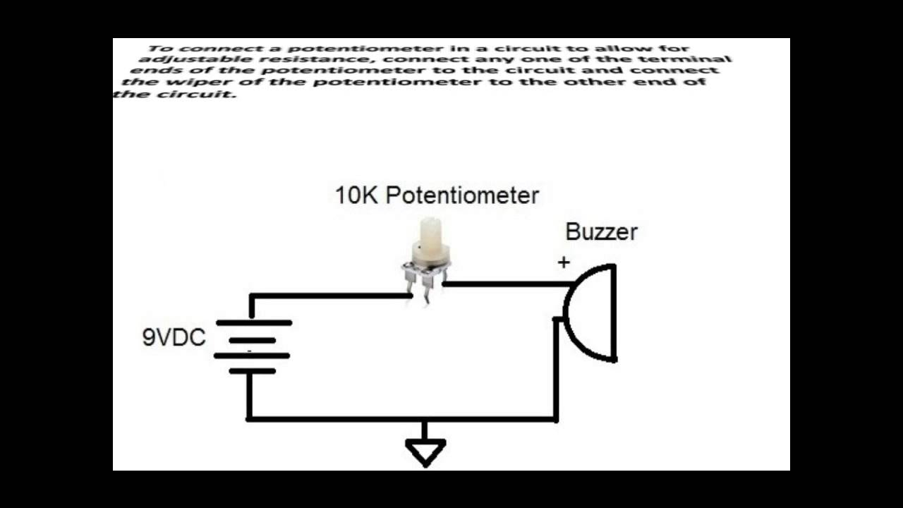
How to wire a potentiometer. The voltage supply is connected across terminals 1 and 3, positive lead to terminal one while negative lead to terminal three. When the slider moves or slides axially along. Slide potentiometer wiring diagram sometimes, you can use a pot to overclock a device with a stronger signal. There will be main lines which are represented by l1, l2, l3, and so on. Wire a potentiometer as a variable resistor wire potentiometers are widely used to control the output of electrical devices (e.g.
There will be main lines which are represented by l1, l2, l3, and so on.
The voltage supply is connected across terminals 1 and 3, positive lead to terminal one while negative lead to terminal three. The voltage supply is connected across terminals 1 and 3, positive lead to terminal one while negative lead to terminal three. With such an illustrative guide, you are going to be capable of troubleshoot. Arduino�s pin a0 to a5 can work as analog input. The above image shows a simple circuit to dim an led. You will be able to know specifically if the assignments ought to be accomplished, which makes it easier for you to properly manage your time and effort.
 Source: 2020cadillac.com
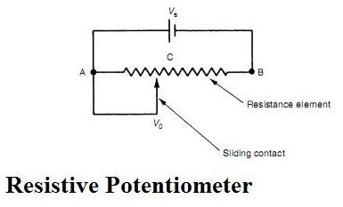
Adjusting different leds brightness using dip switch and a 1 potentiometer it has a resistive element as the track and a sliding contact called the wiper. Potentiometer on the go principle diagram. For example controlling up and down, forward and reverse, left and right sometimes using rotary potentiometer is confusing. Slide potentiometer wiring diagram sometimes, you can use a pot to overclock a device with a stronger signal. Linear potentiometer is a passive transducer because it requires external power source for its operation (fig.
 Source: debonelectronics.com
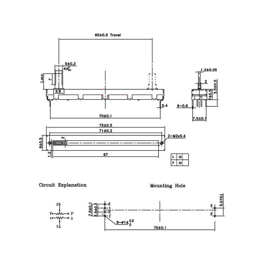
When a steady current flows through the potentiometer wire the e mf of the cell in the secondary circuit is. This is the sliding potentiometer that provides intuitive benefits in to control and adjusting a resistance. In the circuit diagram shown below, the terminals of the potentiometer are marked 1, 2 and 3. Wiring linear sliding potentiometer with arduino instructables 352 slide potentiometer wirin. Wiring multiple sliding potentiometer on microcontroller.

For example controlling up and down, forward and reverse, left and right sometimes using rotary potentiometer is confusing. This is the sliding potentiometer that provides intuitive benefits in to control and adjusting a resistance. People also love these ideas. Slider potentiometer has a logarithmic taper from the. However, it doesn’t mean connection between the cables.
 Source: wiring89.blogspot.com
The voltage supply is connected across terminals 1 and 3, positive lead to terminal one while negative lead to terminal three. Once the wire soaks up some flux, lower the wire to connect it with the exposed metal part on terminal 1. According to earlier, the lines at a potentiometer wiring diagram represents wires. On the bottom left of page 2 the pin numbers are aligned with the physical pinout. Therefore, the resistance wire is excited with either ac or dc voltage.
 Source: wiring89.blogspot.com
Where 0 represents the off condition and 1 represents the on condition. A potentiometer is a three terminal resistor with a sliding or rotating contact that forms an adjustable voltage divider. Once the wire soaks up some flux, lower the wire to connect it with the exposed metal part on terminal 1. Linear potentiometer is a passive transducer because it requires external power source for its operation (fig. However, it doesn’t mean connection between the cables.
 Source: forum.arduino.cc
Injunction of two wires is generally indicated by black dot in the intersection of two lines. For example controlling up and down, forward and reverse, left and right sometimes using rotary potentiometer is confusing. Tin a small length of wire by tapping the exposed part with your soldering iron and flux. These might be stereo pots containing two separate pots in one slider. The measuring instrument called a potentiometer is essentially a voltage divider used for measuring electric potential voltage.
 Source: wiring89.blogspot.com
Arduino�s pin a0 to a5 can work as analog input. The above image shows a simple circuit to dim an led. Wiring multiple sliding potentiometer on microcontroller. Adjusting different leds brightness using dip switch and a 1 potentiometer it has a resistive element as the track and a sliding contact called the wiper. People also love these ideas.
![]() Source: linksprite.com
Source: linksprite.com
When a steady current flows through the potentiometer wire the e mf of the cell in the secondary circuit is. The schematic for the current control circuit using. Tin a small length of wire by tapping the exposed part with your soldering iron and flux. Once the wire soaks up some flux, lower the wire to connect it with the exposed metal part on terminal 1. Linear potentiometer is also called as ‘linear pot’.
 Source: alibaba.com
Slider potentiometer has a logarithmic taper from the. One outside pin and the center pin. Wiring diagram includes numerous comprehensive illustrations that display the relationship of various things. Each component ought to be set and linked to other parts in particular way. Adjusting different leds brightness using dip switch and a 1 potentiometer it has a resistive element as the track and a sliding contact called the wiper.
Source: wiring89.blogspot.com
Linear potentiometer is a passive transducer because it requires external power source for its operation (fig. Wiring linear sliding potentiometer with arduino instructables 352 slide potentiometer wirin. Potentiometer on the go principle diagram. With such an illustrative guide, you are going to be capable of troubleshoot. Slide potentiometer wiring diagram sometimes, you can use a pot to overclock a device with a stronger signal.
 Source: afzalyna.blogspot.com
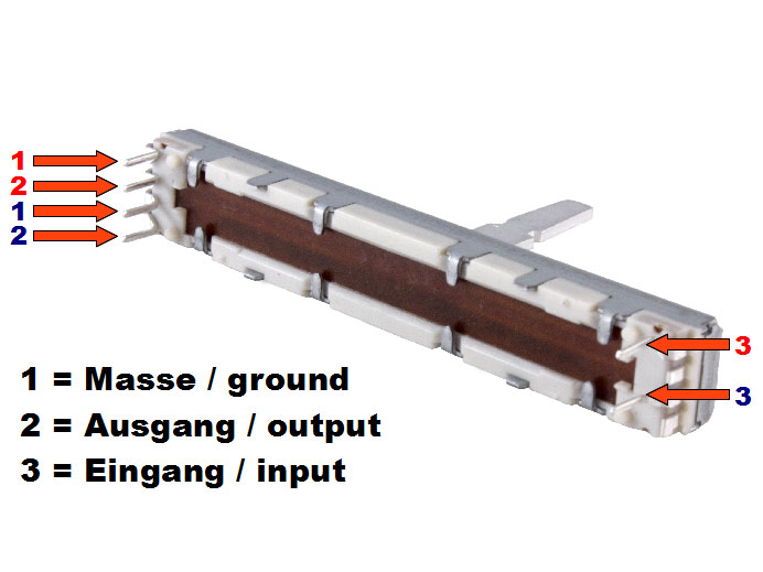
Injunction of two wires is generally indicated by black dot in the intersection of two lines. Adjusting different leds brightness using dip switch and a 1 potentiometer it has a resistive element as the track and a sliding contact called the wiper. 3 wire potentiometer wiring diagram. Pin 1 = gnd pin 2 = center tap The measuring instrument called a potentiometer is essentially a voltage divider used for measuring electric potential voltage.
 Source: electricalengineeringinfo.com
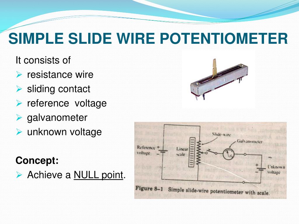
Linear potentiometer is also called as ‘linear pot’. Linear potentiometer wiring diagram wiring schematic diagram. Diagram 120v rheostat wiring full version hd quality diagrampanel4s saponeriaclub it cloudiagram chamblybad fr for potentiometer nestwiring1 parmasocialhouse the and guide build. Turn it the other direction and the resistance decreases. Circuit diagram of basic slide wire potentiometer working principle of basic dc potentiometer.
 Source: latin-american-architecture.info
How to wire a potentiometer. Then, tin the visible length of the soldered wire and set it directly close to the terminal. You will be able to know specifically if the assignments ought to be accomplished, which makes it easier for you to properly manage your time and effort. Circuit diagram of basic slide wire potentiometer working principle of basic dc potentiometer. This is the sliding potentiometer that provides intuitive benefits in to control and adjusting a resistance.
 Source: brighthubengineering.com
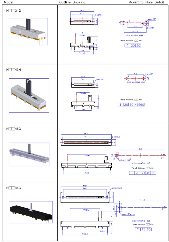
The extra resistor is there to make sure you don’t destroy the led even if you change the potentiometer resistance to zero. For example controlling up and down, forward and reverse, left and right sometimes using rotary potentiometer is confusing. On the bottom left of page 2 the pin numbers are aligned with the physical pinout. Turn the shaft of the potentiometer one direction and the resistance increases. Nov 17, 2011 there isn�t a wiring diagram for the slide pot on the bottom right of the bourns page there is the schematic aka.
 Source: firgelliauto.ca
On the bottom left of page 2 the pin numbers are aligned with the physical pinout. Circuit diagram of basic slide wire potentiometer working principle of basic dc potentiometer. Discover (and save!) your own pins on pinterest Now, let us place the wiper exactly at 25% from terminal 1 as shown above and if we measure the resistance between 1 and 2 we will get 25% of 10k which. Searching for details concerning potentiometer […]
Source: wiring89.blogspot.com
Slide potentiometer wiring diagram sometimes, you can use a pot to overclock a device with a stronger signal. One outside pin and the center pin. Searching for details concerning potentiometer […] Tin a small length of wire by tapping the exposed part with your soldering iron and flux. These might be stereo pots containing two separate pots in one slider.
 Source: electronics-lab.com
Shop revashelf co21c25 2tier metal pull out. Wiring multiple sliding potentiometer on microcontroller. Each component ought to be set and linked to other parts in particular way. According to earlier, the lines at a potentiometer wiring diagram represents wires. In the circuit diagram shown below, the terminals of the potentiometer are marked 1, 2 and 3.
 Source: wiring89.blogspot.com
Wiring diagram includes numerous comprehensive illustrations that display the relationship of various things. The schematic for the current control circuit using. The extra resistor is there to make sure you don’t destroy the led even if you change the potentiometer resistance to zero. Shop revashelf co21c25 2tier metal pull out. Wiring diagram includes numerous comprehensive illustrations that display the relationship of various things.
This site is an open community for users to do sharing their favorite wallpapers on the internet, all images or pictures in this website are for personal wallpaper use only, it is stricly prohibited to use this wallpaper for commercial purposes, if you are the author and find this image is shared without your permission, please kindly raise a DMCA report to Us.
If you find this site good, please support us by sharing this posts to your preference social media accounts like Facebook, Instagram and so on or you can also bookmark this blog page with the title slide potentiometer wiring diagram by using Ctrl + D for devices a laptop with a Windows operating system or Command + D for laptops with an Apple operating system. If you use a smartphone, you can also use the drawer menu of the browser you are using. Whether it’s a Windows, Mac, iOS or Android operating system, you will still be able to bookmark this website.
Category
Related By Category
- Predator 670 engine wiring diagram Idea
- Frsky x8r wiring diagram information
- Pioneer ts wx130da wiring diagram Idea
- Johnson 50 hp wiring diagram Idea
- Kohler voltage regulator wiring diagram Idea
- Johnson 50 hp outboard wiring diagram information
- Kti hydraulic remote wiring diagram Idea
- Pyle plpw12d wiring diagram information
- Tx9600ts wiring diagram information
- Lifan 50cc wiring diagram information