Single phase transformer wiring diagram information
Home » Trending » Single phase transformer wiring diagram information
Your Single phase transformer wiring diagram images are ready. Single phase transformer wiring diagram are a topic that is being searched for and liked by netizens now. You can Find and Download the Single phase transformer wiring diagram files here. Find and Download all free photos.
If you’re searching for single phase transformer wiring diagram pictures information connected with to the single phase transformer wiring diagram interest, you have come to the right site. Our website always gives you suggestions for seeing the maximum quality video and picture content, please kindly hunt and locate more enlightening video articles and images that fit your interests.
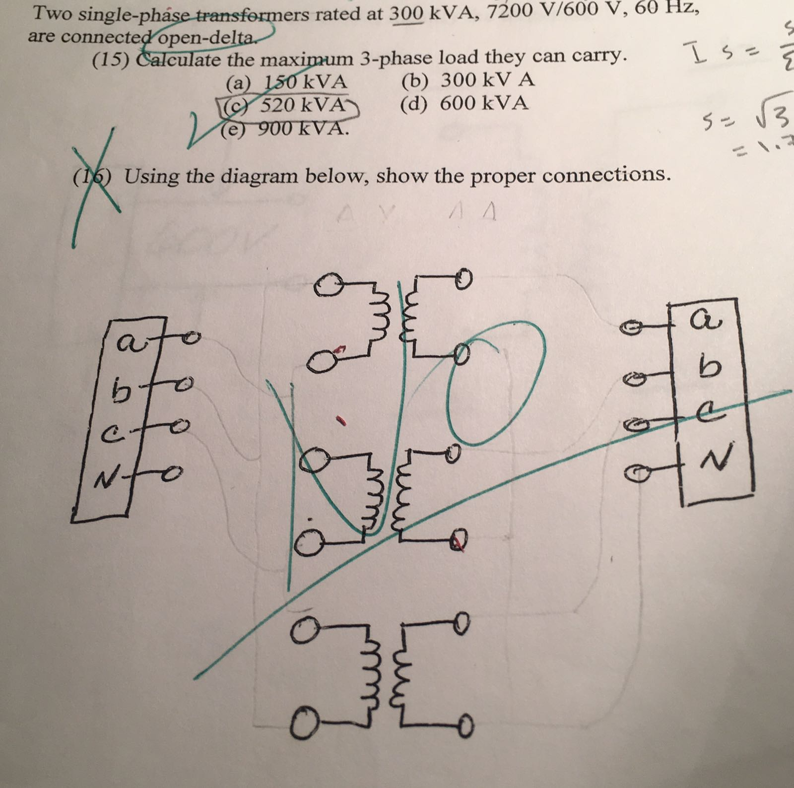
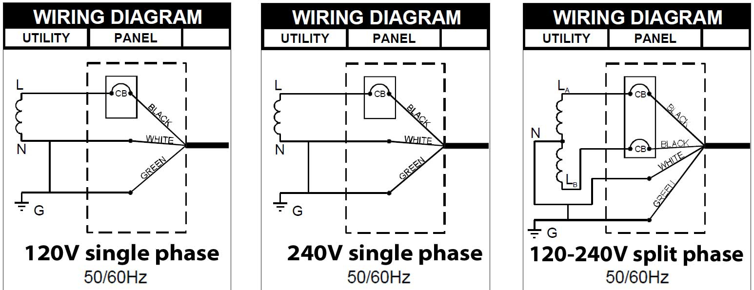
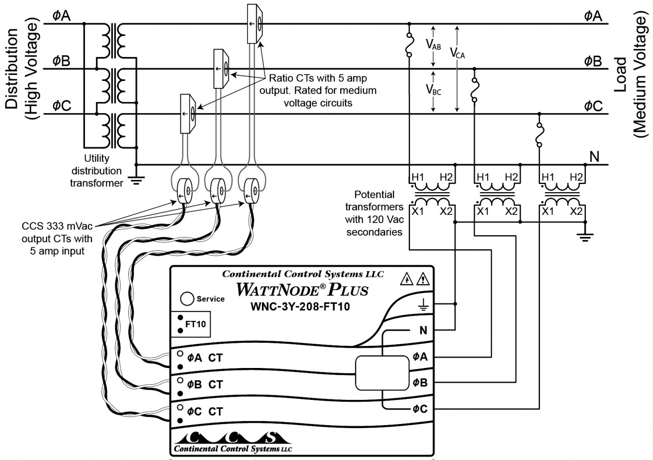
Single Phase Transformer Wiring Diagram. The first symbol indicates the connection of the primary, and the second symbol is the. As stated earlier, the lines in a 240 volt single phase wiring diagram signifies wires. 480v 3 phase to 120/240v single phase transformer wiring diagram. Figure 4 17 single phase transformer connected to give 120 240 volt three wire service.
Micron G003K1KF1A03 Single Phase Transformer 3 kVA / 240 From ebay.com
A single phase transformer consists of two windings viz. Single phase reversing motor starter wiring diagram. There’ll be primary lines which are represented by l1, l2, l3, and so on. Single phase transformer primary and secondary wiring. Single phase wiring diagram for hp pumps with governor switch: 480v single phase wiring diagram 480 volt single phase transformer with 480v 3 phase wiring diagram image size 472 x 264 px image source.
Neutral (x0) provided on three phase, 4 wire primary volts delta, * transformers 15 kva through kva are equipped with a.
Power distribution configurations with three 3ph lines. As an aside this transformer being an enclosed potted type is not really typical of what would be used in a machine tool cabinet. 10 kva transformer primary 240 x 480 secondary 120 federal pacific se2n10f. With this kind of an illustrative guide, you’ll have the ability to troubleshoot, stop, and full your. These instructions will be easy to grasp and use. Single phase transformer wiring diagram.
 Source: createmepink.com
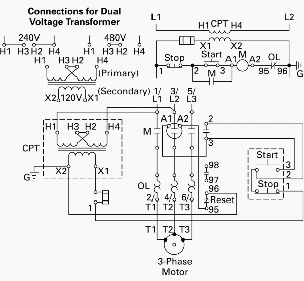
480v single phase wiring diagram 480 volt single phase transformer with 480v 3 phase wiring diagram image size 472 x 264 px image source. None x4x1 h4 h3h2 h1 x2 x3 primary: Wiring diagram will come with several easy to follow wiring diagram guidelines. There’ll be primary lines which are represented by l1, l2, l3, and so on. Their percent impedance must be equal.
 Source: wiring89.blogspot.com
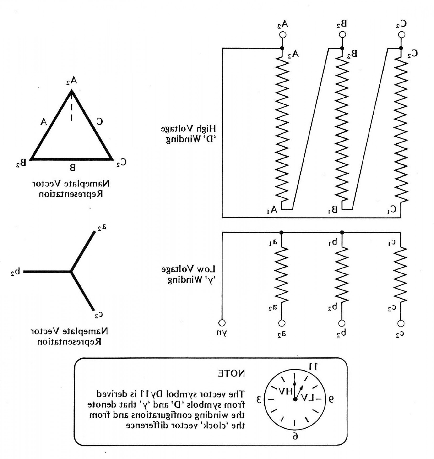
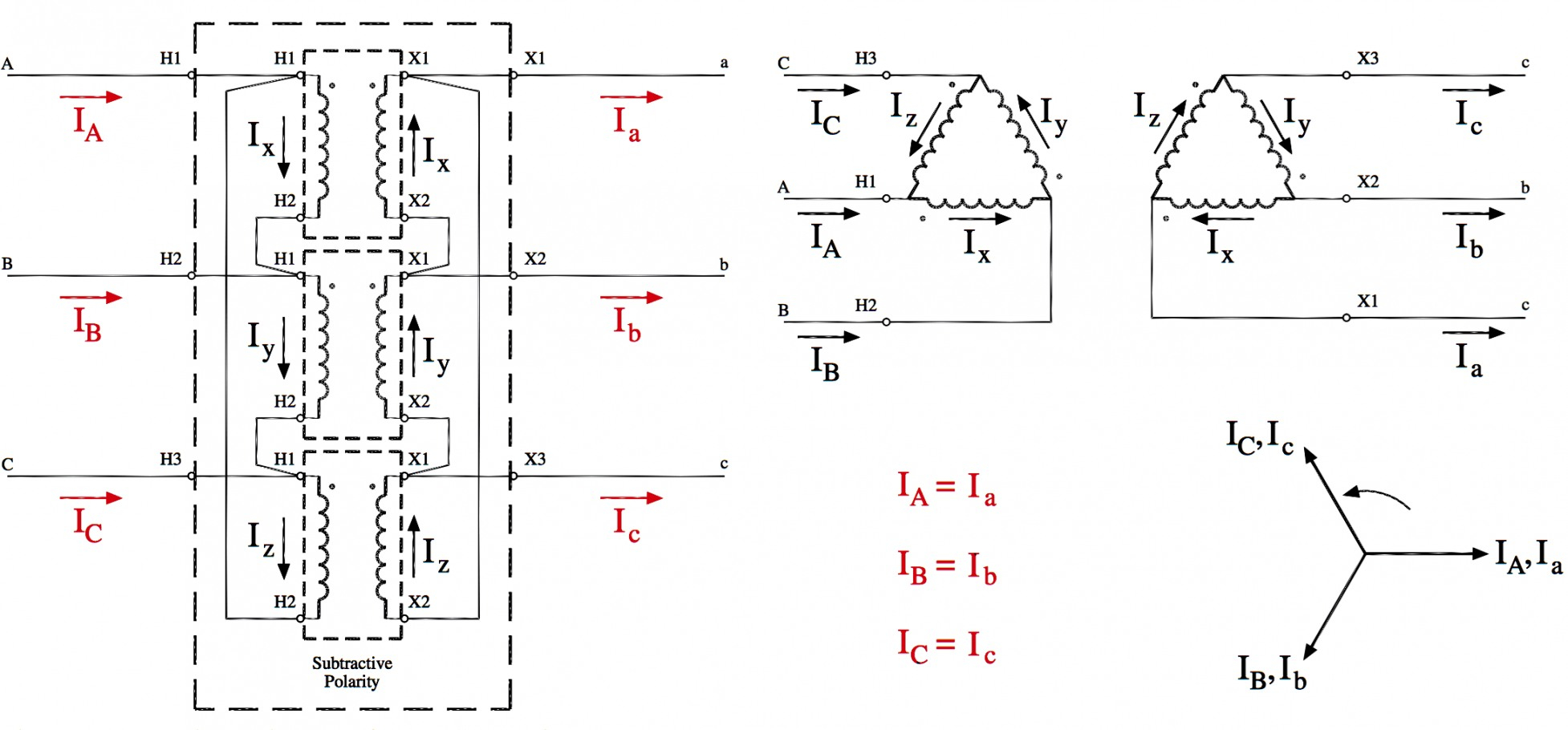
Single phase transformer wiring diagram by vallery masson updated on august 4, 2021 a wiring diagram is an easy graph of the physical connections and physical layout of an electric system or circuit. A single phase transformer consists of two windings viz. Transformers feeders 1 phase 2 wire ecn electrical forums. Single phase transformer primary and secondary wiring. Ings are shown connected to form a v delta to v wye 3 phase step down transformer bank.
Source: ebay.com
The first symbol indicates the connection of the primary, and the second symbol is the. Injunction of 2 wires is usually indicated by black dot to the junction of two lines. Search faster better smarter at zapmeta now. Figure 4 17 single phase transformer connected to give 120 240 volt three wire service. The leads or terminals are marked with hs and xs.
 Source: 2020cadillac.com
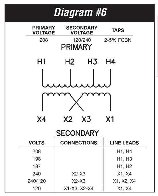
I have x1x2x3x4 wires and h1h2h3h4 wires on the transformer. Construction of single phase transformer. High voltage transformer windings are marked h1, h2, etc., and low voltage transformer windings are marked x1, x2, etc. In the same way as a pain to remove, replace or repair the wiring in an automobile, having an accurate and detailed. In general, connecting individual transformers together requires that:
 Source: hvacrschool.com
But, it doesn’t imply link between the wires. Wiring diagram will come with several easy to follow wiring diagram guidelines. A wiring diagram is a simplified standard pictorial depiction of an electrical circuit. It is most commonly used to increase (‘step up’) or decrease (‘step down’) voltage levels. It’s meant to aid all the average person in building a suitable method.
 Source: ricardolevinsmorales.com
Single phase wiring diagram for hp pumps with governor switch: Primary winding and secondary winding put on a magnetic core.the magnetic core is made from thin sheets (called laminations) of high graded silicon steel and provides a definite path to the magnetic flux. The four basic connections are: Figure 4 17 single phase transformer connected to give 120 240 volt three wire service. Single phase transformer connections the electricity forum.
 Source: wirgram.blogspot.com
14 indicates 125250 vac single phase four wire three pole 15 indicates 250 vac three phase four wire three pole 16 indicates 480 vac three phase four wire three pole 17 indicates 600 vac three phase four wire three pole 21 indicates 120208 vac three phase. Figure 4 17 single phase transformer connected to give 120 240 volt three wire service. Single phase wiring diagram for hp pumps with governor switch: The first symbol indicates the connection of the primary, and the second symbol is the. (with capacitor marking and installation) wiring of the distribution board with rcd , single phase, (from energy meter to the main distribution board) fuse board connection.
 Source: ricardolevinsmorales.com
Figure 4 17 single phase transformer connected to give 120 240 volt three wire service. Product connect a jumper between the h2 and h3 terminals, and bring the v in on h1 & h4. Transformers feeders 1 phase 2 wire ecn electrical forums. Search faster better smarter at zapmeta now. Electrical data wiring diagrams v, v v ac or dc single phase l1 l2 one or more heaters in parallel, single phase.
 Source: 2020cadillac.com
Ings are shown connected to form a v delta to v wye 3 phase step down transformer bank. 480v single phase wiring diagram 480 volt single phase transformer with 480v 3 phase wiring diagram image size 472 x 264 px image source. Electrical data wiring diagrams v, v v ac or dc single phase l1 l2 one or more heaters in parallel, single phase. A single phase transformer consists of two windings viz. Single phase transformer wiring diagram.
 Source: annawiringdiagram.com
10 kva transformer primary 240 x 480 secondary 120 federal pacific se2n10f. As stated earlier, the lines in a 240 volt single phase wiring diagram signifies wires. Wiring of the distribution board , single phase, from energy meter to the main distribution board (without rcd = residual. Wiring diagram will come with several easy to follow wiring diagram guidelines. 10 kva transformer primary 240 x 480 secondary 120 federal pacific se2n10f.
 Source: 2020cadillac.com
480v 3 phase to 120/240v single phase transformer wiring diagram. Compressor wiring diagram single phase. None x4x1 h4 h3h2 h1 x2 x3 primary: But, it doesn’t imply link between the wires. However, it does not imply connection between the wires.
 Source: tankbig.com
None x4x1 h4 h3h2 h1 x2 x3 primary. Single phase wiring diagram for hp pumps with governor switch: Ings are shown connected to form a v delta to v wye 3 phase step down transformer bank. The leads or terminals are marked with hs and xs. In the same way as a pain to remove, replace or repair the wiring in an automobile, having an accurate and detailed.
 Source: schematicandwiringdiagram.blogspot.com
None x4x1 h4 h3h2 h1 x2 x3 primary. 480v 3 phase to 120/240v single phase transformer wiring diagram. 23v.collection of step down transformer v to v wiring diagram. Their percent impedance must be equal. Single phase wiring diagram for hp pumps with governor switch:
 Source: 2020cadillac.com
14 indicates 125250 vac single phase four wire three pole 15 indicates 250 vac three phase four wire three pole 16 indicates 480 vac three phase four wire three pole 17 indicates 600 vac three phase four wire three pole 21 indicates 120208 vac three phase. It’s meant to aid all the average person in building a suitable method. 480v 3 phase to 120/240v single phase transformer wiring diagram. Neutral (x0) provided on three phase, 4 wire primary volts delta, * transformers 15 kva through kva are equipped with a. It reveals the parts of the circuit as simplified shapes, and the power and signal links between the gadgets.
 Source: 2020cadillac.com
Product connect a jumper between the h2 and h3 terminals, and bring the v in on h1 & h4. A wiring diagram is a streamlined standard pictorial depiction of an electrical circuit. 29 best submersible pump images on pinterest. With this kind of an illustrative guide, you’ll have the ability to troubleshoot, stop, and full your. 23v.collection of step down transformer v to v wiring diagram.
 Source: easywiring.info
It is most commonly used to increase (‘step up’) or decrease (‘step down’) voltage levels. Their percent impedance must be equal. There’ll be primary lines which are represented by l1, l2, l3, and so on. According to earlier, the lines in a single phase transformer wiring diagram signifies wires. 14 indicates 125250 vac single phase four wire three pole 15 indicates 250 vac three phase four wire three pole 16 indicates 480 vac three phase four wire three pole 17 indicates 600 vac three phase four wire three pole 21 indicates 120208 vac three phase.
 Source: swgr.com
23v.collection of step down transformer v to v wiring diagram. 480v 3 phase to 120/240v single phase transformer wiring diagram. None x4x1 h4 h3h2 h1 x2 x3 primary. Primary winding and secondary winding put on a magnetic core.the magnetic core is made from thin sheets (called laminations) of high graded silicon steel and provides a definite path to the magnetic flux. But, it doesn’t imply link between the wires.
Source: schematicandwiringdiagram.blogspot.com
Ee25s3h xfmr dry 1ph 25kva 240x480v 120 240v. A single phase transformer consists of two windings viz. Single phase transformer connections the electricity forum. But, it doesn’t imply link between the wires. Wiring of the distribution board , single phase, from energy meter to the main distribution board (without rcd = residual.
This site is an open community for users to share their favorite wallpapers on the internet, all images or pictures in this website are for personal wallpaper use only, it is stricly prohibited to use this wallpaper for commercial purposes, if you are the author and find this image is shared without your permission, please kindly raise a DMCA report to Us.
If you find this site helpful, please support us by sharing this posts to your favorite social media accounts like Facebook, Instagram and so on or you can also bookmark this blog page with the title single phase transformer wiring diagram by using Ctrl + D for devices a laptop with a Windows operating system or Command + D for laptops with an Apple operating system. If you use a smartphone, you can also use the drawer menu of the browser you are using. Whether it’s a Windows, Mac, iOS or Android operating system, you will still be able to bookmark this website.
Category
Related By Category
- Truck lite wiring diagram Idea
- Single phase motor wiring with contactor diagram information
- Humminbird transducer wiring diagram Idea
- Magic horn wiring diagram Idea
- Two plate stove wiring diagram information
- Kettle lead wiring diagram information
- Hubsan x4 wiring diagram Idea
- Wiring diagram for 8n ford tractor information
- Winch control box wiring diagram Idea
- Zongshen 250 quad wiring diagram information