Single phase isolation transformer wiring diagram information
Home » Trending » Single phase isolation transformer wiring diagram information
Your Single phase isolation transformer wiring diagram images are ready. Single phase isolation transformer wiring diagram are a topic that is being searched for and liked by netizens now. You can Find and Download the Single phase isolation transformer wiring diagram files here. Get all royalty-free photos.
If you’re looking for single phase isolation transformer wiring diagram images information linked to the single phase isolation transformer wiring diagram interest, you have visit the ideal site. Our site always provides you with suggestions for refferencing the maximum quality video and picture content, please kindly hunt and locate more informative video articles and graphics that match your interests.
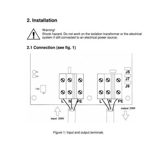
Single Phase Isolation Transformer Wiring Diagram. In the diagram above, taking an installation without an isolation transformer, the device has an earth fault (for example a live conductor has shorted to the chassis). Temco single phase isolation transformers are 50/60 hz rated and come in a nema 3r enclosure for indoor use as well as outdoor protection against rain and sleet. How to wire 3 phase electrical circuit diagram electrical engineering books power engineering. Temco single phase isolation transformers are 50/60 hz rated and come in a nema 3r enclosure for indoor use as well as outdoor protection against rain and sleet.
 Isolation transformer wiring 2 phase power Victron Community From community.victronenergy.com
It’s meant to aid all the average person in building a suitable method. A transformer wiring diagram can be found printed on the transformer nameplate or inside the cover to the wiring compartment. The first step is to figure out the voltage of your phases. Single phase motor with capacitor forward and reverse wiring diagram circuit diagram electrical diagram electrical circuit diagram. As the name suggests these switch devices help to ensure that electrical systems and circuits are completely and safely powered down. Temco single phase isolation transformers are 50/60 hz rated and come in a nema 3r enclosure for indoor use as well as outdoor protection against rain and sleet.
Specifications • 50/60 hz • nema 3r
3 phase isolation transformer wiring diagram pdf, related gallery: The figure below shows schematic diagram for industrial three phase wiring. Temco single phase isolation transformers are 50/60 hz rated and come in a nema 3r enclosure for indoor use as well as outdoor protection against rain and sleet. It makes the procedure for building circuit easier. Hv= higher voltage, lv= lower voltage when bucking and boosting. On the other hand, the diagram is a simplified version of this structure.
 Source: gramwir.blogspot.com
Our standard transformer range covers 10, 16, 32, 50, 63 & 100 amp single phase shore capacities at 230v. These instructions will be easy to grasp and use. This makes the procedure for assembling circuit simpler. The leads or terminals are marked with hs and xs. In general, connecting individual transformers together requires that:
![[DIAGRAM] Hauling Transformer Wiring Diagram FULL Version [DIAGRAM] Hauling Transformer Wiring Diagram FULL Version](https://faceitsalon.com/wp-content/uploads/2018/07/3-phase-isolation-transformer-wiring-diagram-transformer-wiring-diagram-isolation-changing-doorbell-4-wire-12s.jpg) Source: wiring37.fellinishop.it
Source: wiring37.fellinishop.it
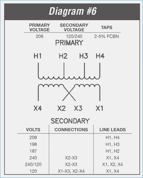
It shows the parts of the circuit as simplified forms and the power and signal links in between the tools. It is most commonly used to increase (‘step up’) or decrease (‘step down’) voltage levels. 208 volt primary single phase isolation transformers. It shows the parts of the circuit as simplified forms and the power and signal links in between the tools. According to earlier the traces in a 3 phase to single phase wiring diagram signifies wires.
 Source: rafiqahumuhabibah.blogspot.com
Our transformers are built to last, guaranteed. Single phase motor with capacitor forward and reverse wiring diagram circuit diagram electrical diagram electrical circuit diagram. Hv= higher voltage, lv= lower voltage when bucking and boosting. On the other hand, the diagram is a simplified version of this structure. 208 volt primary single phase isolation transformers.
 Source: pinterest.com
A transformer is a passive electrical device that transfers electrical energy from one circuit to another through the process of electromagnetic induction. As stated earlier the lines in a 3 phase transformer wiring diagram represents wires. That�s why we back these with a decade long warranty. It is most commonly used to increase (‘step up’) or decrease (‘step down’) voltage levels. What is an and are its advantages instrumentation control engineering you need know uninterruptible power supplies wiring 2 phase victron community understanding the design basics of technical articles single connections electricity forum magic that uses suppress.
 Source: pinterest.com.au
With this kind of an illustrative guide, you’ll have the ability to troubleshoot, stop, and full your. Preparation step 1 turn off the power supplying the circuit to be wired to the motor. It is most commonly used to increase (‘step up’) or decrease (‘step down’) voltage levels. However it doesnt mean connection between the wires. 3 phase isolator wiring diagram.
 Source: headcontrolsystem.com
Single phase wiring diagrams always use wiring diagram supplied on motor nameplate. The figure below shows schematic diagram for industrial three phase wiring. With this kind of an illustrative guide, you’ll have the ability to troubleshoot, stop, and full your. At times the wires will cross. This makes the procedure for assembling circuit simpler.
 Source: faceitsalon.com
Our transformers are built to last, guaranteed. In general, connecting individual transformers together requires that: 3 phase isolation transformer wiring diagram source: 3 phase isolator wiring diagram. Isolation transformer wiring diagram wiring diagram line wiring diagram.
 Source: drivenheisenberg.blogspot.com
The first step is to figure out the voltage of your phases. In 480v single phase transformer wiring diagram, acme single phase transformer wiring diagram, hammond single phase transformer wiring diagram, single phase distribution transformer wiring diagram, single phase isolation transformer wiring diagram, single phase pole mounted transformer wiring diagram, single phase transformer circuit diagram. It is most commonly used to increase (‘step up’) or decrease (‘step down’) voltage levels. Single phase wiring diagrams always use wiring diagram supplied on motor nameplate. The case should be grounded by the primary feed and i usually bond the secondary neutral and ground in the panel or if there no panel then at the transformer with double lug on x0.
 Source: mickygurlz.blogspot.com
Single phase three phase wiring diagrams 1 phase 3 phase wring the star delta y d 3 phase motor starting method by automatic star delta starter. Dual voltage single rotation split phase motor dual voltage reversible rotation capacitor motor single phase wiring. Unit supports 50hz or 60 hz as required single phase chart (requires 1 transformer) low voltage (lv) high voltage Unique how to read electrical schematics diagram wiringdiagram diagramming diagramm visuals visualisation gra isolation transformer transformers diagram. Single phase motor with capacitor forward and reverse wiring diagram circuit diagram electrical diagram electrical circuit diagram.
 Source: community.victronenergy.com
These instructions will be easy to grasp and use. A transformer wiring diagram can be found printed on the transformer nameplate or inside the cover to the wiring compartment. Our standard transformer range covers 10, 16, 32, 50, 63 & 100 amp single phase shore capacities at 230v. The diagram provides visual representation of an electrical arrangement. By vallery masson updated on october 24, 2021.
 Source: electrical-engineering-portal.com
These instructions will be easy to grasp and use. The basics of ac line isolation for safety part 2 solution power electronic tips. This makes the procedure for assembling circuit simpler. They do so by isolating i e. Single phase three phase wiring diagrams 1 phase 3 phase wring the star delta y d 3 phase motor starting method by automatic star delta starter.
 Source: wiring89.blogspot.com
3 phase isolation transformer wiring diagram pdf, related gallery: According to earlier the traces in a 3 phase to single phase wiring diagram signifies wires. 3 phase isolation transformer wiring diagram source: Wiring circuit breaker for trolling motor | guitar wiring diagrams 2 pickups 2 volume 1 tone | 3 gang dimmer switch wiring diagram uk | electrical wiring work in patna |. The case should be grounded by the primary feed and i usually bond the secondary neutral and ground in the panel or if there no panel then at the transformer with double lug on x0.
 Source: wiring89.blogspot.com
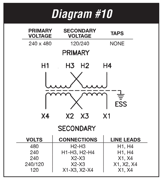
3 phase isolation transformer wiring diagram pdf, related gallery: In the same way as a pain to remove, replace or repair the wiring in an automobile, having an accurate and detailed. The diagram provides visual representation of an electrical arrangement. How to wire a multi tap transformer wiring diagram for cur single phase connections of 10 kva primary 240 x 480 power supply ac circuits install isolation 120v 24v brooders hog hps spartan hammond transformator aansluiten eleq. Single phase three phase wiring diagrams 1 phase 3 phase wring the star delta y d 3 phase motor starting method by automatic star delta starter.

In the same way as a pain to remove, replace or repair the wiring in an automobile, having an accurate and detailed. Wiring diagram a 3 phase isolator with a stop button; Our standard transformer range covers 10, 16, 32, 50, 63 & 100 amp single phase shore capacities at 230v. • ul listed, csa approved. The difficulty in point of fact is that all car is different.
 Source: swgr.com
In general, connecting individual transformers together requires that: The case should be grounded by the primary feed and i usually bond the secondary neutral and ground in the panel or if there no panel then at the transformer with double lug on x0. Information below to select the proper wiring diagram. What is an and are its advantages instrumentation control engineering you need know uninterruptible power supplies wiring 2 phase victron community understanding the design basics of technical articles single connections electricity forum magic that uses suppress. It’s meant to aid all the average person in building a suitable method.
 Source: wiringdiagram.2bitboer.com
• ul listed, csa approved. How to wire 3 phase electrical circuit diagram electrical engineering books power engineering. It makes the procedure for building circuit easier. That�s why we back these with a decade long warranty. Temco single phase isolation transformers are 50/60 hz rated and come in a nema 3r enclosure for indoor use as well as outdoor protection against rain and sleet.
 Source: easywiring.info
Preparation step 1 turn off the power supplying the circuit to be wired to the motor. 2 phase, 3 wire (for separate. Unique how to read electrical schematics diagram wiringdiagram diagramming diagramm visuals visualisation gra isolation transformer transformers diagram. The diagram provides visual representation of an electrical arrangement. Our standard transformer range covers 10, 16, 32, 50, 63 & 100 amp single phase shore capacities at 230v.

The case should be grounded by the primary feed and i usually bond the secondary neutral and ground in the panel or if there no panel then at the transformer with double lug on x0. 3 phase isolation transformer wiring diagram pdf, related gallery: Since neutral and earth are bonded in the consumer unit the system sees this as a short circuit and so a large current will flow which will blow the fuse or trip a circuit breaker. How to wire 3 phase electrical circuit diagram electrical engineering books power engineering. Single phase three phase wiring diagrams 1 phase 3 phase wring the star delta y d 3 phase motor starting method by automatic star delta starter.
This site is an open community for users to do sharing their favorite wallpapers on the internet, all images or pictures in this website are for personal wallpaper use only, it is stricly prohibited to use this wallpaper for commercial purposes, if you are the author and find this image is shared without your permission, please kindly raise a DMCA report to Us.
If you find this site adventageous, please support us by sharing this posts to your own social media accounts like Facebook, Instagram and so on or you can also save this blog page with the title single phase isolation transformer wiring diagram by using Ctrl + D for devices a laptop with a Windows operating system or Command + D for laptops with an Apple operating system. If you use a smartphone, you can also use the drawer menu of the browser you are using. Whether it’s a Windows, Mac, iOS or Android operating system, you will still be able to bookmark this website.
Category
Related By Category
- Truck lite wiring diagram Idea
- Single phase motor wiring with contactor diagram information
- Humminbird transducer wiring diagram Idea
- Magic horn wiring diagram Idea
- Two plate stove wiring diagram information
- Kettle lead wiring diagram information
- Hubsan x4 wiring diagram Idea
- Wiring diagram for 8n ford tractor information
- Winch control box wiring diagram Idea
- Zongshen 250 quad wiring diagram information