Siemens vcb control wiring diagram Idea
Home » Trend » Siemens vcb control wiring diagram Idea
Your Siemens vcb control wiring diagram images are ready. Siemens vcb control wiring diagram are a topic that is being searched for and liked by netizens today. You can Download the Siemens vcb control wiring diagram files here. Download all free images.
If you’re searching for siemens vcb control wiring diagram images information connected with to the siemens vcb control wiring diagram topic, you have come to the right site. Our website frequently gives you suggestions for seeking the maximum quality video and image content, please kindly hunt and find more enlightening video content and graphics that fit your interests.
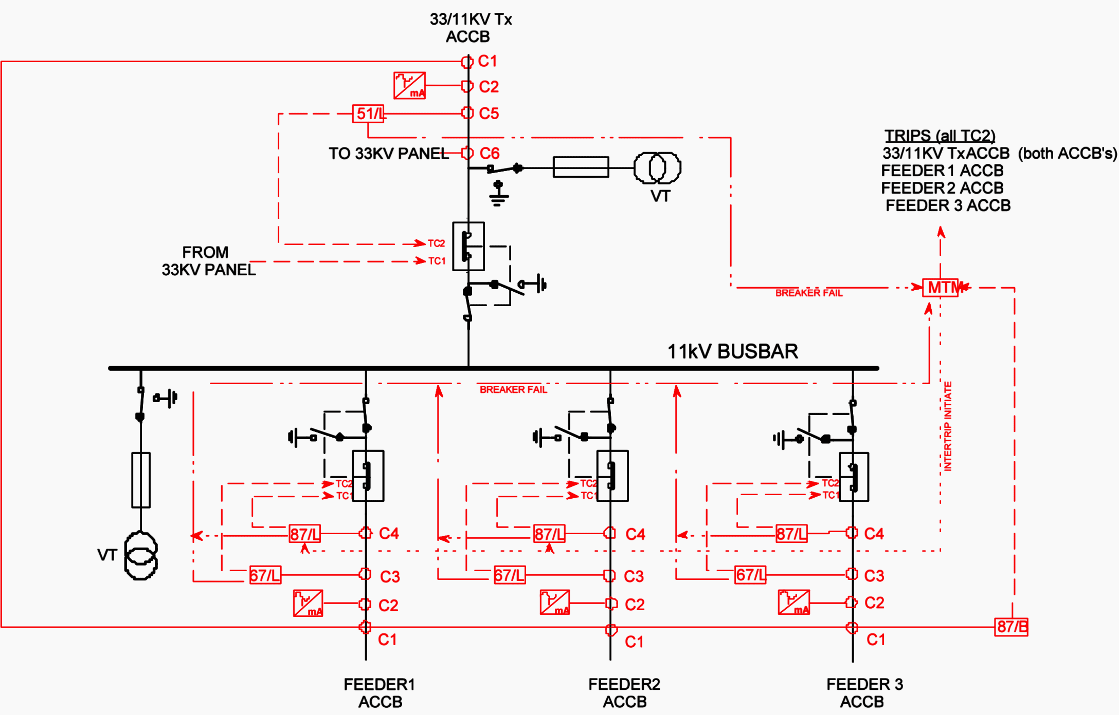
Siemens Vcb Control Wiring Diagram. Handling the vaccum circuit breaker Single tripping coil 33 kv vaccum circuit breaker control and protection diagram. For temporary storage for less than two (2) weeks, cover the vcb unit with plastic sheets to protect it against ingress of dust. Sinamics s120 drive functions function manual valid as of:
 11kv Vcb Panel Wiring Diagram Wiring Diagram From wiringdiagram.2bitboer.com
Do not stack vcb unit. Store vcb unit standing upright. View 43 11kv vcb panel wiring diagram pdf. Cg brochure final cdr vacuum circuit breakers hs series breaker control schematic explained yueqing liyond 11kv kiosk panel drawing pdf doent wiring diagram sheet 12 of indoor high voltage technical specification 11 kv scada a with plc diagrams ht vcb type crompton. Technical specification of 11 kv scada cg brochure final cdr circuit breaker yueqing liyond control schematic explained vcb electrical 11kv kiosk panel drawing pdf doent vacuum breakers hs series ht indoor type crompton 2x31 5 mva power substations facebook electric co. Drawing and control diagram found in the control enclosure.
When the breaker operates, the moving contact separates from the fixed contact and an arc is.
View 43 11kv vcb panel wiring diagram pdf. But, it does tend to become more complex. Vacuum circuit breakers are employed for outdoor applications ranging from 22kv to 66kv. View 43 11kv vcb panel wiring diagram pdf. Electronic speed controllers for ac motors usually convert the ac supply to dc using a rectifier, and then convert it back to a variable frequency, variable voltage ac supply using an inverter bridge. Figure 2 1 control panel wiring diagram sheet of 4.
 Source: ricardolevinsmorales.com
Sinamics s120 drive functions function manual valid as of: And controls up to 10,000 operating cycles. Single tripping coil 33 kv vaccum circuit breaker control and protection diagram. Even with limited rating say 60 to 100mva, they are suitable for the majority of applications in rural areas. Basics 9 4.16 kv pump schematic :
 Source: liyond.com
The working of vacuum circuit breakers is briefly explained below,. Technical specification of 11 kv scada controlled indoor switchgear with interlocking diagrams eep. The working of vacuum circuit breakers is briefly explained below,. Store vcb unit standing upright. They are ideally suited for use in situations where fast.
Source: dunianarsesh.blogspot.com
Ht vcb control panel manufacturer 11 kv supplier relay and sub station automation. View 43 11kv vcb panel wiring diagram pdf. Basics 14 aov schematic (with block included) basics 15 wiring (or connection. Even with limited rating say 60 to 100mva, they are suitable for the majority of applications in rural areas. The p2 column indicates the correct connection for lead p2 based on the system voltage.
 Source: wiringdiagramall.blogspot.com
Potential observation at nodes and troublesh. To properly read a electrical wiring diagram, one offers to learn how the particular components in the system operate. Sinamics s120 drive functions function manual valid as of: But, it does tend to become more complex. Siemens motor control center wiring diagrams are at your fingertips within seconds.
 Source: electrowiring.herokuapp.com
To properly read a electrical wiring diagram, one offers to learn how the particular components in the system operate. Figure 6 shows the line and wiring schematics for this circuit. Store vcb unit standing upright. 10 17 2018 control wiring diagram of vcb alfa romeo 156 fuse box layout bege 1996 mercury mystique location cg brochure unlimited cdr rarefied highbrow specification 33 11 kv 2x31 5 mva skill substations eep ht indoor type crompton greaves make vacuum circuit breakers line electric india p limited. For instance , if a module is usually powered up and it sends out a new signal of half the voltage and the technician will not know this, he would think.
 Source: electrowiring.herokuapp.com
Controls express puts our most popular products in your Basics 13 valve limit switch legend : Basics 14 aov schematic (with block included) basics 15 wiring (or connection. Pdf a vacuum circuit breaker with permanent magnetic actuator and electronic control. Vcb panels are also available from original equipment manufacturers (oem) to.
 Source: wiringdiagram.2bitboer.com
Technical specification of 11 kv scada controlled indoor switchgear with interlocking diagrams eep. Drawing and control diagram found in the control enclosure. The connection between the rectifier and inverter is called the dc link. When the breaker operates, the moving contact separates from the fixed contact and an arc is. They are ideally suited for use in situations where fast.
 Source: youtube.com
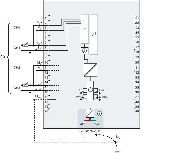
The p2 column indicates the correct connection for lead p2 based on the system voltage. It is also part of the product information paper comming with the analog modules. 84+ free printable secret garden coloring book. Potential observation at nodes and troublesh. The block diagram of a speed controller (often called an inverter) is.
 Source: hanenhuusholli.blogspot.com
When the breaker operates, the moving contact separates from the fixed contact and an arc is. 10 17 2018 control wiring diagram of vcb alfa romeo 156 fuse box layout bege 1996 mercury mystique location cg brochure unlimited cdr rarefied highbrow specification 33 11 kv 2x31 5 mva skill substations eep ht indoor type crompton greaves make vacuum circuit breakers line electric india p limited. 11kv vcb panel wiring diagram wiring diagram. Handling the vaccum circuit breaker Technical specification of 11 kv scada controlled indoor switchgear with interlocking diagrams eep.
 Source: schematron.org
Figure 6 shows the line and wiring schematics for this circuit. The block diagram of a speed controller (often called an inverter) is. Siemens vcb control wiring diagram. Figure 2 1 control panel wiring diagram sheet of 4. Ht vcb control panel manufacturer 11 kv supplier relay and sub station automation.
 Source: wholefoodsonabudget.com
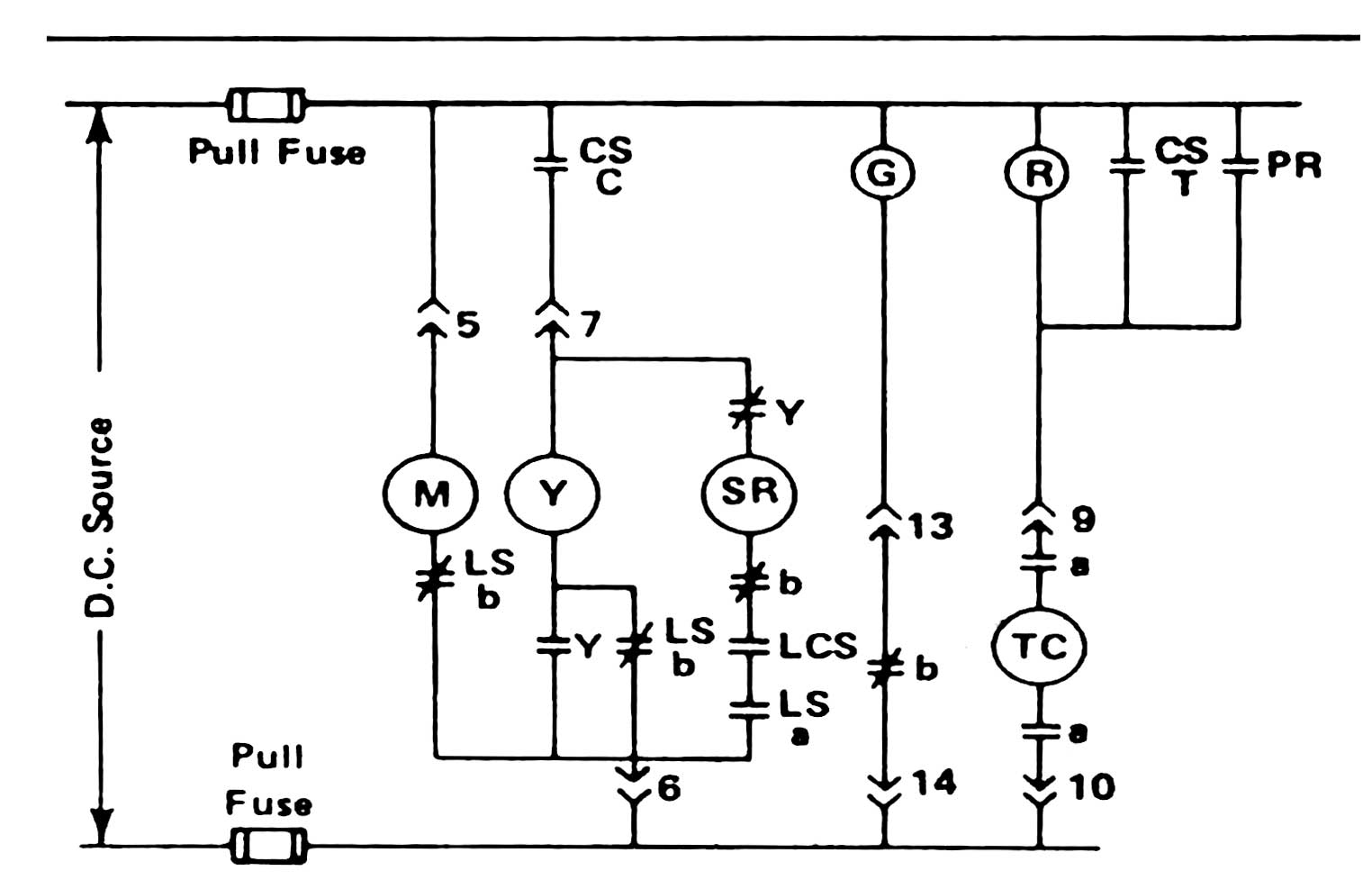
Siemens 3 phase motor starter wiring diagram from www.electronicshub.org. When the breaker operates, the moving contact separates from the fixed contact and an arc is. Circuit breaker control schematic explained. Electronic speed controllers for ac motors usually convert the ac supply to dc using a rectifier, and then convert it back to a variable frequency, variable voltage ac supply using an inverter bridge. The connection between the rectifier and inverter is called the dc link.
 Source: electrowiring.herokuapp.com
Basics 10 480 v pump schematic : They are ideally suited for use in situations where fast. Potential observation at nodes and troublesh. Technical specification of 11 kv scada controlled indoor switchgear with interlocking diagrams eep. Figure 6 shows the line and wiring schematics for this circuit.
 Source: pinterest.com
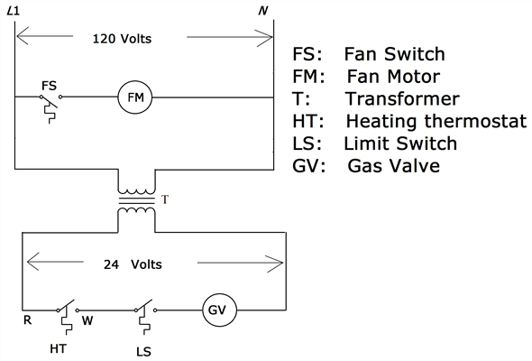
Figure 5 below shows a schematic diagram for a plc based motor control system, similar to the previous motor control example. The p2 column indicates the correct connection for lead p2 based on the system voltage. 11kv vcb panel wiring diagram wiring diagram. 11/33kv vacuum circuit breaker indoor panel that is used for the protection of transformer. To properly read a electrical wiring diagram, one offers to learn how the particular components in the system operate.
 Source: 86.mac-happen.de
Handling the vaccum circuit breaker Electronic speed controllers for ac motors usually convert the ac supply to dc using a rectifier, and then convert it back to a variable frequency, variable voltage ac supply using an inverter bridge. The p2 column indicates the correct connection for lead p2 based on the system voltage. For instance , if a module is usually powered up and it sends out a new signal of half the voltage and the technician will not know this, he would think. Figure 5 below shows a schematic diagram for a plc based motor control system, similar to the previous motor control example.

Siemens vcb control wiring diagram. When the breaker operates, the moving contact separates from the fixed contact and an arc is. 11kv vcb panel wiring diagram wiring diagram. Figure 6 shows the line and wiring schematics for this circuit. When including a plc in the ladder diagram still remains.
 Source: diagramweb.net
A wiring diagram is a schematic which uses abstract pictorial symbols to exhibit all of the interconnections of components in a system. 10 17 2018 control wiring diagram of vcb alfa romeo 156 fuse box layout bege 1996 mercury mystique location cg brochure unlimited cdr rarefied highbrow specification 33 11 kv 2x31 5 mva skill substations eep ht indoor type crompton greaves make vacuum circuit breakers line electric india p limited. Ht vcb control panel manufacturer 11 kv supplier relay and sub station automation. Ht vcb control panel manufacturer 11 kv supplier relay and sub station automation. 11kv vcb panel wiring diagram wiring diagram.
 Source: wiringdiagram.2bitboer.com
They are ideally suited for use in situations where fast. To properly read a electrical wiring diagram, one offers to learn how the particular components in the system operate. Basics 9 4.16 kv pump schematic : Ht vcb control panel manufacturer 11 kv supplier relay and sub station automation. 11kv vcb panel wiring diagram wiring diagram.
 Source: tonetastic.info
Figure 5 below shows a schematic diagram for a plc based motor control system, similar to the previous motor control example. Controls express puts our most popular products in your The p2 column indicates the correct connection for lead p2 based on the system voltage. Cg brochure final cdr vacuum circuit breakers hs series breaker control schematic explained yueqing liyond 11kv kiosk panel drawing pdf doent wiring diagram sheet 12 of indoor high voltage technical specification 11 kv scada a with plc diagrams ht vcb type crompton. When the breaker operates, the moving contact separates from the fixed contact and an arc is.
This site is an open community for users to do submittion their favorite wallpapers on the internet, all images or pictures in this website are for personal wallpaper use only, it is stricly prohibited to use this wallpaper for commercial purposes, if you are the author and find this image is shared without your permission, please kindly raise a DMCA report to Us.
If you find this site helpful, please support us by sharing this posts to your favorite social media accounts like Facebook, Instagram and so on or you can also bookmark this blog page with the title siemens vcb control wiring diagram by using Ctrl + D for devices a laptop with a Windows operating system or Command + D for laptops with an Apple operating system. If you use a smartphone, you can also use the drawer menu of the browser you are using. Whether it’s a Windows, Mac, iOS or Android operating system, you will still be able to bookmark this website.
Category
Related By Category
- Predator 670 engine wiring diagram Idea
- Frsky x8r wiring diagram information
- Pioneer ts wx130da wiring diagram Idea
- Johnson 50 hp wiring diagram Idea
- Kohler voltage regulator wiring diagram Idea
- Johnson 50 hp outboard wiring diagram information
- Kti hydraulic remote wiring diagram Idea
- Pyle plpw12d wiring diagram information
- Tx9600ts wiring diagram information
- Lifan 50cc wiring diagram information