Series parallel testing board wiring diagram information
Home » Trending » Series parallel testing board wiring diagram information
Your Series parallel testing board wiring diagram images are ready. Series parallel testing board wiring diagram are a topic that is being searched for and liked by netizens now. You can Download the Series parallel testing board wiring diagram files here. Get all free vectors.
If you’re searching for series parallel testing board wiring diagram pictures information connected with to the series parallel testing board wiring diagram interest, you have visit the right blog. Our site always gives you suggestions for downloading the maximum quality video and picture content, please kindly surf and locate more informative video articles and images that fit your interests.
Series Parallel Testing Board Wiring Diagram. I don�t think i can make it any clearer than this: 2 pickup teles phostenix wiring diagrams series parallel wire diagram. And the drawing reza referred you to shows the same thing in a different way. You get several components one after the other.
 How to Make Series parallel Electrical Testing Board (In From deepakkumaryadav.in
The new parallel breakout board appears a bit different but the process of wiring and testing is the same. Much more common than series circuits are those wired in parallel—including most household branch circuits powering light fixtures, outlets, and appliances. Download our wiring diagrams for our complete range of bosch controls and modules. To wired the electric testing board first of all connect the neutral wire to lamp holder and then connect the phase wire to outlet terminal and then connect a wire between socket / outlet and holder as. This is exactly the same wiring arrangement as the diagram on the overview page. We need to calculate r1 ǁ r2 first before adding r3.
Place wires along the lines and fix them with the help of clips.
Cts push pull pot for series parallel help talkbass com in 2021 series parallel parallel wiring bass making series testing board for low resistance appliances diagram design boards electrical diagram A parallel circuit is also a closed circuit where the current divides into two or more paths before coming back together to complete the full circuit. Mark switch and bulb location points and draw lines for wiring on the wooden board. Rules regarding series and parallel circuits. We need to calculate r1 ǁ r2 first before adding r3. Contacts 1 and 3 and contacts 2 and 4 are connected together as they are spring loaded.
 Source: deepakkumaryadav.in
Rules regarding series and parallel circuits. Calculating leds in series parallel in display board. 2 pickup teles phostenix wiring diagrams series parallel wire diagram. The new parallel breakout board appears a bit different but the process of wiring and testing is the same. If you follow the circuit diagram from one side of the cell to the other, you should pass through all the different components, one after the other.
 Source: learnelectrician.blogspot.com
Download pdf 0 8 mb therm 660 ef efo. And the drawing reza referred you to shows the same thing in a different way. The first three lamps (b1, b2 & b3) are connected in parallel while switches (s1, s2 & s3) are wired in series accordingly. Mark switch and bulb location points and draw lines for wiring on the wooden board. Download our wiring diagrams for our complete range of bosch controls and modules.
 Source: youtube.com
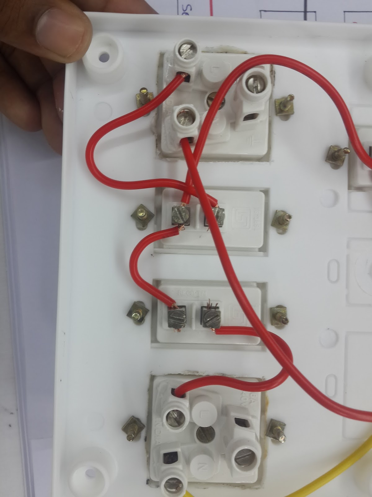
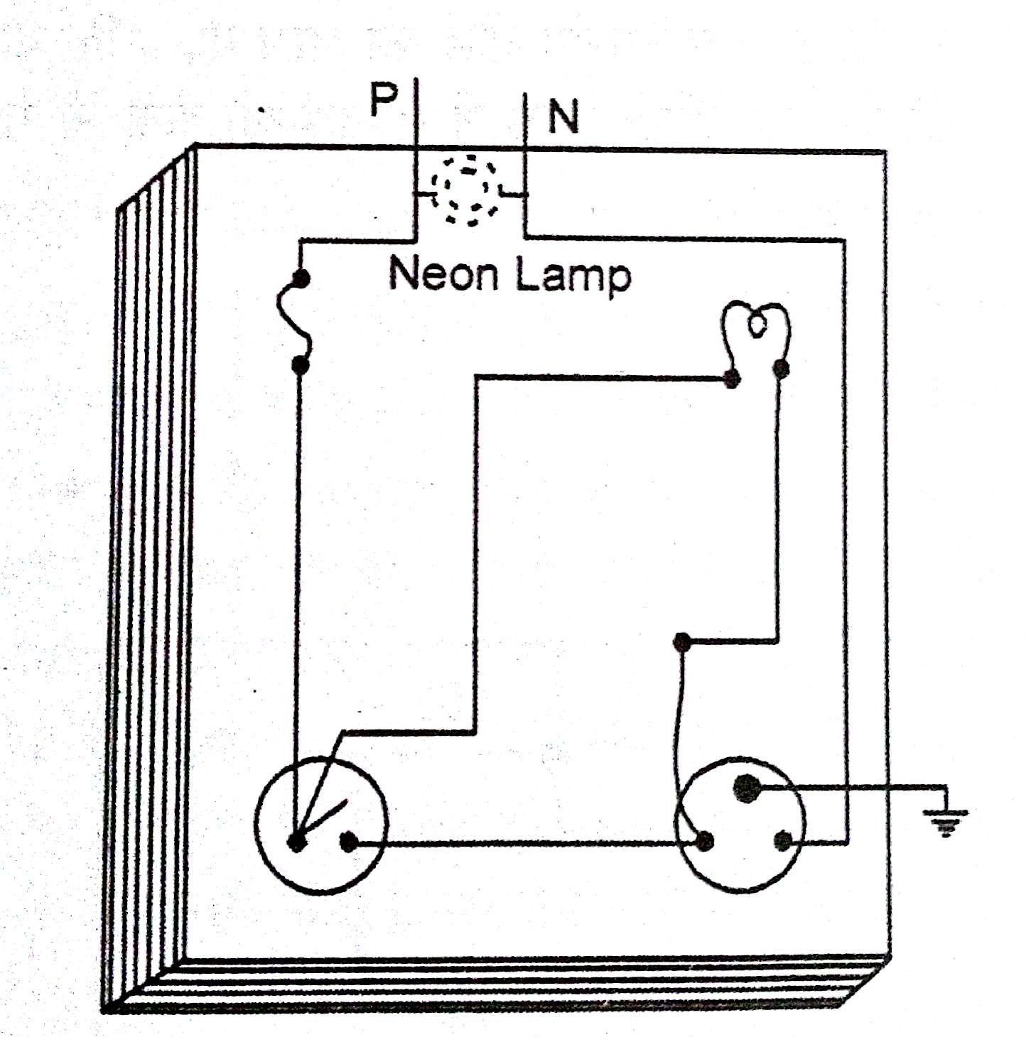
Adding speakers in parallel decreases the overall resistance of the circuit. You get several components one after the other. Complete the wiring as per the wiring diagram. Lower impedance raises acoustical output. After t hat connect a wire between outlet 2nd terminal and bulb socket 2nd terminal same connect an electric wire between the switch 2nd terminal and the light bulb socket holder 2nd terminal.
 Source: youtube.com
Complete the wiring as per the wiring diagram. A series parallel switch consists of four sets of contacts that we ll call 1 2 3 and 4. In the above wiring diagram, we have connected a 63a fuse in series with the main input phase supply. Contacts 1 and 3 and contacts 2 and 4 are connected together as they are spring loaded. Calculating leds in series parallel in display board.
 Source: deepakkumaryadav.in
0.5k ω+ 0.5k ω= 1kω the parallel resistances are: This is exactly the same wiring arrangement as the diagram on the overview page. The above diagram shows another way to create a bank of batteries. 0.5k ω+ 0.5k ω= 1kω the parallel resistances are: Each lamp is connected between l and n.
 Source: youtube.com
Parallel circuits are the simplest electrical circuit to wire. The double lines between r1 and r2 is a symbol for parallel. This is the way how all professional cnc machines end switches were wired. The negative voice coil connection will attach to the positive connection of the second voice coil. If you are only wiring two voice coils in series, the negative connection on the second voice coil will then.
 Source: deepakkumaryadav.in
Voltage drops add to equal total voltage. Each lamp is connected between l and n. B7, b8, b9 and b10 are in series with each other while they are parallel with the first three bulbs (b1, b2 & b3) while the switches. Cts push pull pot for series parallel help talkbass com in 2021 series parallel parallel wiring bass making series testing board for low resistance appliances diagram design boards electrical diagram Follow the orientations as shown in the circuit diagram.
 Source: youtube.com
First, start with the clean schematic diagram and all components secured to the terminal strip, with no connecting wires: Wiring configuration for 2 speakers in parallel two 4 ohm speakers = 2 ohm load this gives each speaker an 4 ohm impedance. And this coil is added in parallel order of supply. Complete the wiring as per the wiring diagram. Home uncategorized raptor 3018 wiring diagram.
 Source: youtube.com
0.5k ω+ 0.5k ω= 1kω the parallel resistances are: There are two parallel �rails�, l and n. The negative voice coil connection will attach to the positive connection of the second voice coil. Any number of lamps can be added, simply by extending the l and n conductors to other lamps. How to make an series testing board in hindi, series board connection, series board diagram, series lamp, series testing board kaise banaye, series board wir.
 Source: deepakkumaryadav.in
In a parallel circuit, you will never have a black wire connected to a red wire (contrasted with example of series circuit shown above). Support topic get support tutorial information. To test it, just connect a 12 volt supply to the common led positive and the common resistor negative. The double lines between r1 and r2 is a symbol for parallel. This is exactly the same wiring arrangement as the diagram on the overview page.
 Source: deepakkumaryadav.in
0.5k ω+ 0.5k ω= 1kω the parallel resistances are: Batteries joined together in parallel and series: All components share the same (equal) current. In the above wiring diagram, we have connected a 63a fuse in series with the main input phase supply. You get several components one after the other.
 Source: youtube.com
We need to calculate r1 ǁ r2 first before adding r3. After t hat connect a wire between outlet 2nd terminal and bulb socket 2nd terminal same connect an electric wire between the switch 2nd terminal and the light bulb socket holder 2nd terminal. Download our wiring diagrams for our complete range of bosch controls and modules. To wired the electric testing board first of all connect the neutral wire to lamp holder and then connect the phase wire to outlet terminal and then connect a wire between socket / outlet and holder as. The first three lamps (b1, b2 & b3) are connected in parallel while switches (s1, s2 & s3) are wired in series accordingly.
 Source: youtube.com
Resistors r2 and r3 are seen to be connected in parallel, and resistor r1 is in series with the parallel combinations of r2 and r3. Connected in series & parallel _____ deltran corporation, 801 u.s. Next, trace the wire connection from one side of the battery to the first component in the schematic, securing a connecting wire. So 63a is enough for this switchboard. The first three lamps (b1, b2 & b3) are connected in parallel while switches (s1, s2 & s3) are wired in series accordingly.
 Source: deepakkumaryadav.in
Place wires along the lines and fix them with the help of clips. So 63a is enough for this switchboard. Rules regarding series and parallel circuits. We need to calculate r1 ǁ r2 first before adding r3. Resistors r2 and r3 are seen to be connected in parallel, and resistor r1 is in series with the parallel combinations of r2 and r3.
 Source: youtube.com
It’s likely though, you’ve already read the wikipedia page about series and parallel circuits here, maybe a few other google search results on the subject and are still unclear or wanting more specific information as it pertains to leds. Next, trace the wire connection from one side of the battery to the first component in the schematic, securing a connecting wire. Home uncategorized raptor 3018 wiring diagram. Resistances add to equal total resistance. Adding speakers in parallel decreases the overall resistance of the circuit.
 Source: youtube.com
This is the way how all professional cnc machines end switches were wired. •r1 and r2 are in parallel and r3 is in series with r1 ǁ r2. 2 pickup teles phostenix wiring diagrams series parallel wire diagram. Wiring diagram arrives with a number of easy to follow wiring diagram directions. You get several components one after the other.
 Source: electguru.com
Much more common than series circuits are those wired in parallel—including most household branch circuits powering light fixtures, outlets, and appliances. First, start with the clean schematic diagram and all components secured to the terminal strip, with no connecting wires: 1k ω+ 0.5k ω= 1.5 k ω The new parallel breakout board appears a bit different but the process of wiring and testing is the same. 1k ω/ 2 = 0.5k ω the series and parallel values are then added for the value of rt:
 Source: deepakkumaryadav.in
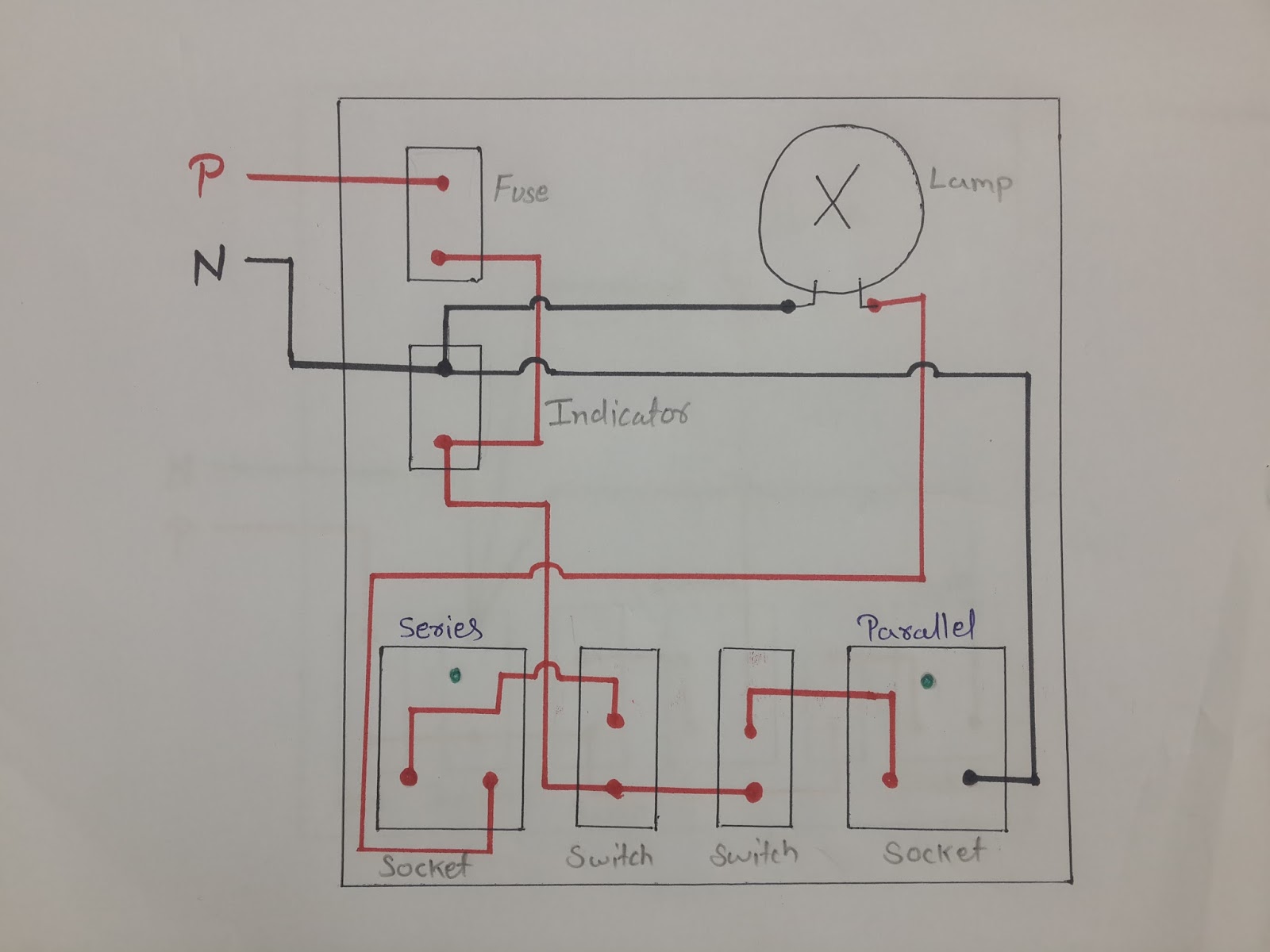
In the above wiring diagram, we have connected a 63a fuse in series with the main input phase supply. In this diagram, the total load of the circuit is 56a(calculated by the total of all switches ratings). Complete the wiring as per the wiring diagram. Test the working of the bulbs by giving electric supply to the circuit. Parallel circuits are the simplest electrical circuit to wire.
This site is an open community for users to do sharing their favorite wallpapers on the internet, all images or pictures in this website are for personal wallpaper use only, it is stricly prohibited to use this wallpaper for commercial purposes, if you are the author and find this image is shared without your permission, please kindly raise a DMCA report to Us.
If you find this site good, please support us by sharing this posts to your preference social media accounts like Facebook, Instagram and so on or you can also save this blog page with the title series parallel testing board wiring diagram by using Ctrl + D for devices a laptop with a Windows operating system or Command + D for laptops with an Apple operating system. If you use a smartphone, you can also use the drawer menu of the browser you are using. Whether it’s a Windows, Mac, iOS or Android operating system, you will still be able to bookmark this website.
Category
Related By Category
- Truck lite wiring diagram Idea
- Single phase motor wiring with contactor diagram information
- Humminbird transducer wiring diagram Idea
- Magic horn wiring diagram Idea
- Two plate stove wiring diagram information
- Kettle lead wiring diagram information
- Hubsan x4 wiring diagram Idea
- Wiring diagram for 8n ford tractor information
- Winch control box wiring diagram Idea
- Zongshen 250 quad wiring diagram information