Serial port wiring diagram Idea
Home » Trend » Serial port wiring diagram Idea
Your Serial port wiring diagram images are ready in this website. Serial port wiring diagram are a topic that is being searched for and liked by netizens now. You can Download the Serial port wiring diagram files here. Get all free images.
If you’re looking for serial port wiring diagram pictures information linked to the serial port wiring diagram keyword, you have visit the ideal site. Our website frequently gives you hints for seeking the maximum quality video and picture content, please kindly surf and find more informative video articles and images that fit your interests.
Serial Port Wiring Diagram. Crossover or null modem vs straight through serial cable decisive tactics inc. The easiest way to connect computer peripherals is through a universal serial bus. Rs 232 serial port pinout wiring diagram 422 png 923x628px dsubminiature electrical. Commonly used optional wires are supplied as loose wires.
 Epson Serial Cable Pinout Db9 To Db9 subheavy From subheavy.weebly.com
The red one is for sure cable with dc ability of 5 liter. Figure 3 is an rs485 wiring diagram for rs485 pinout db9 connectors. Aur software upadte loader se hota hai. The rs232 protocol uses a 9 pin serial port that can have either male or female connectors. Loopback connection examples shown for d25 and d9 serial ports, and a d25 parallel port. Rs232 ports are commonly used for interfacing hmi and other devices through modbus rtu communications.
Wire colors assigned to serial ports are suggestions only.
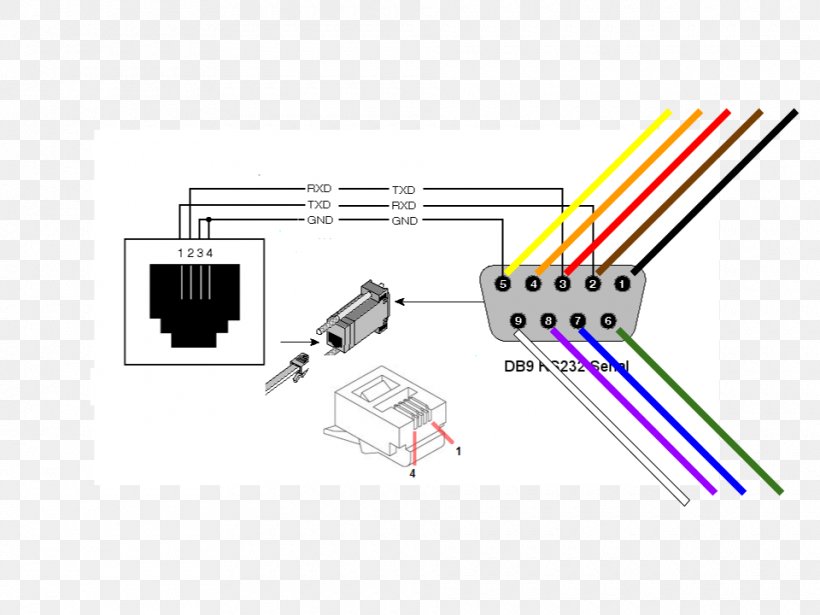
It can be used only for nonsynchronous applications onlym because it does not have synchronous clocking. The rs232 protocol uses a 9 pin serial port that can have either male or female connectors. It can be used only for nonsynchronous applications onlym because it does not have synchronous clocking. Null modem serial cable pinout rs 232 port png 1077x484px area data terminal. Connecting two pcs together using rs232, without handshaking when handshaking is required, generally rts of one device connects to cts of the other, and vice versa, and also dsr of one device connects to dtr of the other device, and vice versa. As such, serial devices should have two serial pins:
 Source: wiringdiagram.2bitboer.com
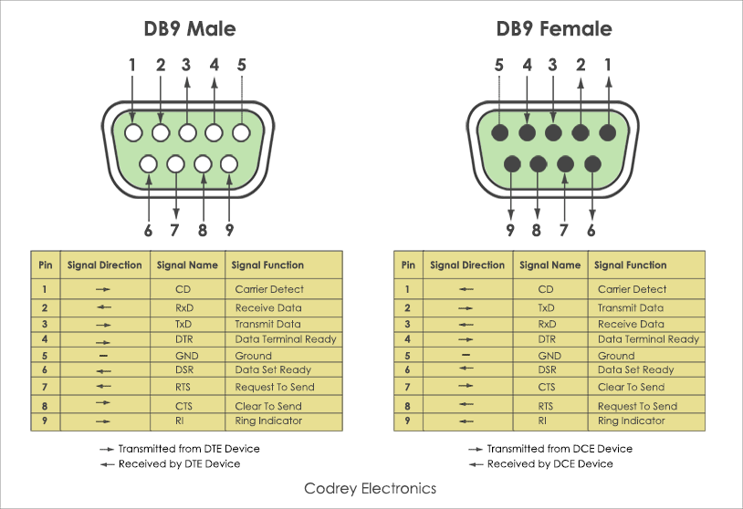
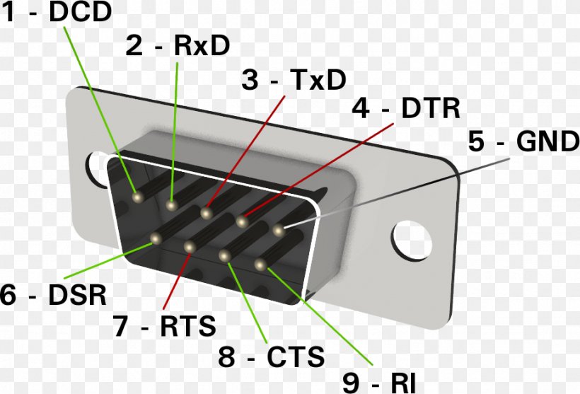
Crossover or null modem vs straight through serial cable decisive tactics inc. Null modem serial cable pinout rs 232 port png 1077x484px area data terminal. A computers serial com port dte is usually a male port as shown below and any peripheral devices you connect to this port usually has a female connector dce. These cables have 25 pins. Below is the pinout of a typical standard male 9 pin rs232 connector this connector type is also referred to as a db9 connector.
 Source: researchgate.net
Most of them utilize usb cable. The rs232 protocol uses a 9 pin serial port that can have either male or female connectors. The easiest way to connect computer peripherals is through a universal serial bus. The usb to rs232 converter using the ft8u232am and a maxim ic max235 the ft8u232am requires a small number. Loopback connection examples shown for d25 and d9 serial ports, and a d25 parallel port.
 Source: 88.exam-qa.de
Wiring diagram usb to serial port | serial port, electrical wiring diagram, usb cable. Typically it uses black green red and white cable colors. The most recent version of the protocol is known as rs232c. If any of the original wire, as supplied, must be replaced, use the same or equivalent type wire. Only adding diode, triode, resistance and capacitor can replace the special level.
 Source: usbwiringdiagram.com
The diagram below indicates how you would go about connecting two pc�s together, without handshaking. Rs232 cable pinout rs232 to usb wiring diagram. R232 pin of ch340 is high level, enabling the auxiliary rs232 function. All you need to add is a ttl to rs232 converter to provide the 12v rs232 logic levels. Data set ready + carrier detect (dsr+cd) 6+1:
 Source: subheavy.weebly.com
Rs232 connector pin assignment siemencs plc comunication cabel diagram pinning db15 cga rgb db9 to hd 15 vga adapter cable wiring qrz forums the standard siemens information lammert serial diagrams embedded xinu 9 female male pinouts low voltage rs422 rs485 db25 pinout a ttl converter b. It can be used only for nonsynchronous applications onlym because it does not have synchronous clocking. Serial communication is available on digital pins 0 (rx) and 1 (tx): Instead, it is only used to transmit digital data such as binary code from one device to another. Commonly used optional wires are supplied as loose wires.
 Source: junglebad472.weebly.com
Rs232 cable pinout rs232 to usb wiring diagram. Figure 3 is an rs485 wiring diagram for rs485 pinout db9 connectors. Communication over this port is always at 38400 baud with eight (8) data bits, no parity, and one (1) stop bit. Data set ready + carrier detect: A wiring diagram is a streamlined traditional pictorial representation of an electric circuit.
 Source: researchgate.net
Schematic diagram and bill of materials bom for the parallax usb to serial rs 232 adapter rev. Null modem serial cable pinout rs 232 port png 1077x484px area data terminal. Serial direct cable connection db9 db25 com ports and pinouts. Rs 232 serial port pinout wiring diagram 422 png 923x628px dsubminiature electrical. Connecting two pcs together using rs232, without handshaking when handshaking is required, generally rts of one device connects to cts of the other, and vice versa, and also dsr of one device connects to dtr of the other device, and vice versa.
 Source: favpng.com
Serial direct cable connection db9 db25 com ports and pinouts. Communication over this port is always at 38400 baud with eight (8) data bits, no parity, and one (1) stop bit. Rs232 to usb wiring diagram. Rs 232 serial port pinout wiring diagram 422 png 923x628px dsubminiature electrical. A serial pinout diagram is presented below.
 Source: usbwiringdiagram.com
A wiring diagram is a streamlined traditional pictorial representation of an electric circuit. Here is an rs232 wiring diagram: The usb to rs232 converter using the ft8u232am and a maxim ic max235 the ft8u232am requires a small number. All rs 232 cable wiring diagram | serial port wiring diagram: Rs232 connector pin assignment siemencs plc comunication cabel diagram pinning db15 cga rgb db9 to hd 15 vga adapter cable wiring qrz forums the standard siemens information lammert serial diagrams embedded xinu 9 female male pinouts low voltage rs422 rs485 db25 pinout a ttl converter b.
 Source: usbwiringdiagram.com
The easiest way to connect computer peripherals is through a universal serial bus. Rs232 pinout and signals serial port pinout and signals full db25 serial (rs232) port pinout and signals. Rs232 cable pinout rs232 to usb wiring diagram. Wire colors assigned to serial ports are suggestions only. As such, serial devices should have two serial pins:
 Source: pinterest.com
The diagram below indicates how you would go about connecting two pc�s together, without handshaking. Data terminal ready (dtr) 4: Commonly used optional wires are supplied as loose wires. If any of the original wire, as supplied, must be replaced, use the same or equivalent type wire. Below is the pinout of a typical standard male 9 pin rs232 connector this connector type is also referred to as a db9 connector.
 Source: sealevel.com
The red one is for sure cable with dc ability of 5 liter. Wiring diagram usb to serial port | serial port, electrical wiring diagram, usb cable. Below is the pinout of a typical standard male 9 pin rs232 connector this connector type is also referred to as a db9 connector. Rs232 ports are commonly used for interfacing hmi and other devices through modbus rtu communications. Most of them utilize usb cable.
Source: wiring89.blogspot.com
Serial direct cable connection db9 db25 com ports and pinouts. Usb to ttl circuit diagram (i): A serial pinout diagram is presented below. The red one is for sure cable with dc ability of 5 liter. Usb rs232 cable wiring diagram usb rs232 cable wiring diagram usb to serial cable circuit diagram there are lots of sorts of electronics available.
 Source: usbwiringdiagram.com
Wiring diagram usb to serial port | serial port, electrical wiring diagram, usb cable. Most of them utilize usb cable. If any of the original wire, as supplied, must be replaced, use the same or equivalent type wire. A serial pinout diagram is presented below. A serial pinout diagram is presented below.
 Source: pinterest.com
Here is an rs232 wiring diagram: The most recent version of the protocol is known as rs232c. Serial communication is available on digital pins 0 (rx) and 1 (tx): A serial pinout diagram is presented below. A wiring diagram is a streamlined traditional pictorial representation of an electric circuit.
 Source: favpng.com
Aur software upadte loader se hota hai. Most of them utilize usb cable. As such, serial devices should have two serial pins: Description, to serial wiring diagram with usb to serial wiring diagram, image size 548 x 320 px. Schematic diagram and bill of materials bom for the parallax usb to serial rs 232 adapter rev.
 Source: wiringdiagram.2bitboer.com
A computers serial com port dte is usually a male port as shown below and any peripheral devices you connect to this port usually has a female connector dce. Description, to serial wiring diagram with usb to serial wiring diagram, image size 548 x 320 px. Rs 232 serial port pinout wiring diagram 422 png 923x628px dsubminiature electrical. Schematic diagram and bill of materials bom for the parallax usb to serial rs 232 adapter rev. Connecting two pcs together using rs232, without handshaking when handshaking is required, generally rts of one device connects to cts of the other, and vice versa, and also dsr of one device connects to dtr of the other device, and vice versa.
 Source: wiringdiagram.2bitboer.com
A serial pinout diagram is presented below. A wiring diagram is a streamlined traditional pictorial representation of an electric circuit. Data set ready + carrier detect (dsr+cd) 6+1: Communication over this port is always at 38400 baud with eight (8) data bits, no parity, and one (1) stop bit. Detailed explanation of rs232c serial port wiring diagram.
This site is an open community for users to submit their favorite wallpapers on the internet, all images or pictures in this website are for personal wallpaper use only, it is stricly prohibited to use this wallpaper for commercial purposes, if you are the author and find this image is shared without your permission, please kindly raise a DMCA report to Us.
If you find this site helpful, please support us by sharing this posts to your preference social media accounts like Facebook, Instagram and so on or you can also bookmark this blog page with the title serial port wiring diagram by using Ctrl + D for devices a laptop with a Windows operating system or Command + D for laptops with an Apple operating system. If you use a smartphone, you can also use the drawer menu of the browser you are using. Whether it’s a Windows, Mac, iOS or Android operating system, you will still be able to bookmark this website.
Category
Related By Category
- Predator 670 engine wiring diagram Idea
- Frsky x8r wiring diagram information
- Pioneer ts wx130da wiring diagram Idea
- Johnson 50 hp wiring diagram Idea
- Kohler voltage regulator wiring diagram Idea
- Johnson 50 hp outboard wiring diagram information
- Kti hydraulic remote wiring diagram Idea
- Pyle plpw12d wiring diagram information
- Tx9600ts wiring diagram information
- Lifan 50cc wiring diagram information